EP1128480A2 - Unlocking aid - Google Patents
Unlocking aid Download PDFInfo
- Publication number
- EP1128480A2 EP1128480A2 EP01104642A EP01104642A EP1128480A2 EP 1128480 A2 EP1128480 A2 EP 1128480A2 EP 01104642 A EP01104642 A EP 01104642A EP 01104642 A EP01104642 A EP 01104642A EP 1128480 A2 EP1128480 A2 EP 1128480A2
- Authority
- EP
- European Patent Office
- Prior art keywords
- unlocking
- contacts
- housing
- unlocking aid
- constructed
- Prior art date
- Legal status (The legal status is an assumption and is not a legal conclusion. Google has not performed a legal analysis and makes no representation as to the accuracy of the status listed.)
- Granted
Links
Images


Classifications
-
- H—ELECTRICITY
- H01—ELECTRIC ELEMENTS
- H01R—ELECTRICALLY-CONDUCTIVE CONNECTIONS; STRUCTURAL ASSOCIATIONS OF A PLURALITY OF MUTUALLY-INSULATED ELECTRICAL CONNECTING ELEMENTS; COUPLING DEVICES; CURRENT COLLECTORS
- H01R43/00—Apparatus or processes specially adapted for manufacturing, assembling, maintaining, or repairing of line connectors or current collectors or for joining electric conductors
- H01R43/20—Apparatus or processes specially adapted for manufacturing, assembling, maintaining, or repairing of line connectors or current collectors or for joining electric conductors for assembling or disassembling contact members with insulating base, case or sleeve
- H01R43/22—Hand tools
-
- H—ELECTRICITY
- H01—ELECTRIC ELEMENTS
- H01R—ELECTRICALLY-CONDUCTIVE CONNECTIONS; STRUCTURAL ASSOCIATIONS OF A PLURALITY OF MUTUALLY-INSULATED ELECTRICAL CONNECTING ELEMENTS; COUPLING DEVICES; CURRENT COLLECTORS
- H01R13/00—Details of coupling devices of the kinds covered by groups H01R12/70 or H01R24/00 - H01R33/00
- H01R13/40—Securing contact members in or to a base or case; Insulating of contact members
- H01R13/42—Securing in a demountable manner
- H01R13/422—Securing in resilient one-piece base or case, e.g. by friction; One-piece base or case formed with resilient locking means
- H01R13/4223—Securing in resilient one-piece base or case, e.g. by friction; One-piece base or case formed with resilient locking means comprising integral flexible contact retaining fingers
Definitions
- the invention relates to an unlocking aid for unlocking contacts which are attached to a line and retained in a housing by a primary latch mechanism.
- Primary latch mechanisms are typically constructed on the contacts in the form of outwardly protruding latching springs which reach behind an edge in the housing of the plug. Such primary latch mechanisms can typically only be released using sharp objects which bend the latching springs downwards, insofar as they are accessible from the outside at all. In so doing, however, the latching springs are usually plastically deformed so that either they subsequently have to be bent back again or the contacts cannot be re-used.
- a special tool for unlocking the contacts is therefore necessary, this special tool making it possible to release all the primary latching mechanisms at the same time. Since there are a plurality of housings and the contacts are not always arranged at the same spacing from one another, there is no universal tool which can be used to unlock the contacts. Thus, a separate unlocking tool is required for each type of housing. Since the assembly engineer seldom has the appropriate unlocking tool at hand, the contacts are usually damaged.
- the object of this invention is therefore to provide an unlocking aid for unlocking contacts which are attached to a line and which are each received in the housing with a primary latching mechanism such that the assembly engineer always has an unlocking aid to hand and damage to the contacts is avoided.
- the assembly engineer always has the appropriate unlocking aid available.
- the assembly engineer will not use any auxiliary tool, which always entails a risk of damaging the contacts. Because all the primary latching mechanisms of the contacts can be released at the same time using the unlocking aid, the housing can easily be separated from the line with the contacts attached.
- the primary latching mechanisms are constructed in the form of latching springs on the contacts, and windows through which the unlocking aid presses the latching springs down to unlock them are provided in the housing at the locations of the primary latching mechanisms.
- the unlocking aid is constructed in the form of a part which is separable from the plug, such as the secondary locking member for the contacts.
- unlocking aid in one piece with the housing and to release the primary latching mechanisms of the contacts only by way of a pivotal mechanism.
- FIG 1 illustrates a plugging connection having the unlocking aid 1 according to the invention.
- the plugging connection comprises a housing 2 and a mating plug 3, each of which is connected to a line 5 by way of contacts 4 (not illustrated in Figure 1).
- the line 5 is constructed in the form of a flexible line, but could equally well be a low-profile (flat) line with a plurality of cores (leads) arranged next to one another.
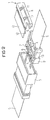
- Figure 2 shows the plugging connection according to Figure 1 in an exploded illustration.
- the contacts 4 attached to the line 5 are visible.
- the unlocking aid 1 is constructed to be separable from the housing 2 and may be pushed onto the housing 2 as illustrated in Figure 1, from the terminal side, that is to say from the side on which the line 5 is brought up to the housing 2.
- the unlocking aid is substantially U-shaped in cross-section and comprises a base wall 8, a rear wall 9 and a top wall 10.
- Arranged on the rear wall 9 are two protrusions 11 which are spaced from one another by the same amount as the windows 7 are in the housing 2.
- the protrusions 11 are dimensioned such that they may be inserted through the windows 7 from above.
- the unlocking aid 1 as illustrated in Figure 2 is drawn off the housing 2 and placed on the housing 2 from above as illustrated in Figure 3 such that the protrusions 11 release the primary latching mechanism 6 through the windows 7.
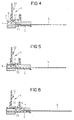
- Figures 4 to 6 illustrate the three phases of release of the primary latching mechanism, with the housing 2, the unlocking aid 1 and the line 5 each being illustrated in section.
- the unlocking aid 1 abuts by means of its rear wall laterally with respect to the protrusions 11 against the upper side of the housing 2, as illustrated in Figures 5 and 6. This ensures that the primary latching mechanism 6 is only pressed down by an amount equivalent to the height of the protrusions 11 and thus the possibility of over-bending of the primary latching mechanism 6 is eliminated. Over-bending would carry a risk of the primary latching mechanism 6 being plastically deformed and the contacts 4 no longer being securely fixed when they are re-inserted into the housing 2.
- the unlocking aid 1 is at the same time constructed to form a secondary securing means.
- the unlocking aid 1 has a continuous rib 12 on the underside of the top wall 10, and this continuous rib 12 is inserted into a corresponding recess 13 in the housing 2 in order to lock the contacts 4 in the housing 2 and hence (see Figures 4 and 5) reaches form-fittingly (in an interlocking manner) behind the contacts 4.
- the housing 2 is inserted into the mating plug 3 of box-shaped construction with the unlocking aid 1 pushed on, so that it is no longer possible to lift off the unlocking aid upwards, and thus the secondary securing means also cannot be separated when the plugging connection is made.
- the invention is not restricted to the example embodiment illustrated.
Landscapes
- Engineering & Computer Science (AREA)
- Manufacturing & Machinery (AREA)
- Details Of Connecting Devices For Male And Female Coupling (AREA)
Abstract
Description
Claims (7)
- An unlocking aid (1) for unlocking contacts (4) which are attached to a line (5) and which are received in a housing (2) by way of a respective primary latching mechanism (6), characterised in that the unlocking aid (1) is integrated in the housing (2) and all the primary latching mechanisms (6) of the contacts (4) can be released at the same time using the unlocking aid (1).
- The unlocking aid according to claim 1, characterised in that the primary latching mechanism (6) is constructed in each case in the form of a latching spring on the contacts (4).
- The unlocking aid according to claim 1 or 2, characterised in that windows (7), through which the unlocking aid (1) acts from the outside on the primary latching mechanism (6), are provided at those locations in the housing (2) where contacts (4) are arranged on the primary latching mechanism (6).
- The unlocking aid according to any one of claims 1 to 3, characterised in that in each case a part separable from the plug is constructed.
- The unlocking aid according to any one of claims 1 to 4, characterised in that it is constructed on a secondary locking member for the contacts (4).
- The unlocking aid according to any one of claims 1 to 5, characterised in that protrusions (11) are constructed on it, and these are arranged in the same grid spacing as the windows (7) in the housing (2).
- The unlocking aid according to any one of claims 1 to 6, characterised in that the line is constructed in the form of a flexible line.
Priority Applications (1)
| Application Number | Priority Date | Filing Date | Title |
|---|---|---|---|
| EP20010104642 EP1128480B1 (en) | 2000-02-23 | 2001-02-23 | Unlocking aid |
Applications Claiming Priority (3)
| Application Number | Priority Date | Filing Date | Title |
|---|---|---|---|
| EP00103751 | 2000-02-23 | ||
| EP00103751 | 2000-02-23 | ||
| EP20010104642 EP1128480B1 (en) | 2000-02-23 | 2001-02-23 | Unlocking aid |
Publications (3)
| Publication Number | Publication Date |
|---|---|
| EP1128480A2 true EP1128480A2 (en) | 2001-08-29 |
| EP1128480A3 EP1128480A3 (en) | 2002-01-23 |
| EP1128480B1 EP1128480B1 (en) | 2003-02-12 |
Family
ID=26070585
Family Applications (1)
| Application Number | Title | Priority Date | Filing Date |
|---|---|---|---|
| EP20010104642 Expired - Lifetime EP1128480B1 (en) | 2000-02-23 | 2001-02-23 | Unlocking aid |
Country Status (1)
| Country | Link |
|---|---|
| EP (1) | EP1128480B1 (en) |
Family Cites Families (2)
| Publication number | Priority date | Publication date | Assignee | Title |
|---|---|---|---|---|
| US4635355A (en) * | 1986-01-06 | 1987-01-13 | Molex Incorporated | Tool for electrical terminals |
| JP3216779B2 (en) * | 1995-02-23 | 2001-10-09 | 矢崎総業株式会社 | Method for correcting incomplete insertion of terminal fitting in connector and correction jig |
-
2001
- 2001-02-23 EP EP20010104642 patent/EP1128480B1/en not_active Expired - Lifetime
Also Published As
| Publication number | Publication date |
|---|---|
| EP1128480B1 (en) | 2003-02-12 |
| EP1128480A3 (en) | 2002-01-23 |
Similar Documents
| Publication | Publication Date | Title |
|---|---|---|
| EP1065756B1 (en) | Locking and unlocking mechanism of cable connector and method for locking and unlocking | |
| US8038460B2 (en) | Safety device for a plug (patch guard) | |
| EP0580133B1 (en) | Electrical connector | |
| EP0734101A2 (en) | Electrical connector position assurance system | |
| EP0795934A2 (en) | Connector provided with a retainer | |
| JP2596866Y2 (en) | Connector with mating confirmation mechanism | |
| US5044975A (en) | Cable connector locking arrangement | |
| CN102171893A (en) | Connector, electronic apparatus, method for removing connector | |
| AU2010217370B2 (en) | Modular connector | |
| JP4162214B2 (en) | Electrical connector assembly | |
| US5772461A (en) | Locking mechanism for interconnecting two mated connectors | |
| CN101282016A (en) | Slide lock panel-mount connector | |
| EP0445263B1 (en) | Edge connector with board latching devices | |
| US7175464B2 (en) | Latching device for a connector | |
| JPH0517821Y2 (en) | ||
| US20020016103A1 (en) | Unlocking aid | |
| EP1085617A1 (en) | A connector | |
| US6685506B1 (en) | Connector and a method for connecting such connector with a mating connector | |
| EP1926193A1 (en) | A locking construction, connector provided therewith and unlocking method | |
| CN111834788A (en) | Electrical terminal housing with terminal lock | |
| EP1128480B1 (en) | Unlocking aid | |
| US6390834B1 (en) | Protective device for a plug connector | |
| EP1347536A2 (en) | Terminal position device apparatus, methods and articles of manufacture for securing sealed male connectors | |
| JPH0530306Y2 (en) | ||
| US6361242B1 (en) | Connector security latching mechanism |
Legal Events
| Date | Code | Title | Description |
|---|---|---|---|
| PUAI | Public reference made under article 153(3) epc to a published international application that has entered the european phase |
Free format text: ORIGINAL CODE: 0009012 |
|
| AK | Designated contracting states |
Kind code of ref document: A2 Designated state(s): AT BE CH CY DE DK ES FI FR GB GR IE IT LI LU MC NL PT SE TR |
|
| AX | Request for extension of the european patent |
Free format text: AL;LT;LV;MK;RO;SI |
|
| PUAL | Search report despatched |
Free format text: ORIGINAL CODE: 0009013 |
|
| AK | Designated contracting states |
Kind code of ref document: A3 Designated state(s): AT BE CH CY DE DK ES FI FR GB GR IE IT LI LU MC NL PT SE TR |
|
| AX | Request for extension of the european patent |
Free format text: AL;LT;LV;MK;RO;SI |
|
| RIC1 | Information provided on ipc code assigned before grant |
Free format text: 7H 01R 13/42 A, 7H 01R 43/22 B, 7H 01R 13/436 B |
|
| 17P | Request for examination filed |
Effective date: 20020215 |
|
| GRAH | Despatch of communication of intention to grant a patent |
Free format text: ORIGINAL CODE: EPIDOS IGRA |
|
| 17Q | First examination report despatched |
Effective date: 20020425 |
|
| AKX | Designation fees paid |
Free format text: AT BE CH CY DE DK ES FI FR GB GR IE IT LI LU MC NL PT SE TR |
|
| GRAH | Despatch of communication of intention to grant a patent |
Free format text: ORIGINAL CODE: EPIDOS IGRA |
|
| GRAA | (expected) grant |
Free format text: ORIGINAL CODE: 0009210 |
|
| AK | Designated contracting states |
Designated state(s): AT BE CH CY DE DK ES FI FR GB GR IE IT LI LU MC NL PT SE TR |
|
| PG25 | Lapsed in a contracting state [announced via postgrant information from national office to epo] |
Ref country code: FI Free format text: LAPSE BECAUSE OF FAILURE TO SUBMIT A TRANSLATION OF THE DESCRIPTION OR TO PAY THE FEE WITHIN THE PRESCRIBED TIME-LIMIT Effective date: 20030212 Ref country code: CH Free format text: LAPSE BECAUSE OF FAILURE TO SUBMIT A TRANSLATION OF THE DESCRIPTION OR TO PAY THE FEE WITHIN THE PRESCRIBED TIME-LIMIT Effective date: 20030212 Ref country code: BE Free format text: LAPSE BECAUSE OF FAILURE TO SUBMIT A TRANSLATION OF THE DESCRIPTION OR TO PAY THE FEE WITHIN THE PRESCRIBED TIME-LIMIT Effective date: 20030212 Ref country code: TR Free format text: LAPSE BECAUSE OF FAILURE TO SUBMIT A TRANSLATION OF THE DESCRIPTION OR TO PAY THE FEE WITHIN THE PRESCRIBED TIME-LIMIT Effective date: 20030212 Ref country code: AT Free format text: LAPSE BECAUSE OF FAILURE TO SUBMIT A TRANSLATION OF THE DESCRIPTION OR TO PAY THE FEE WITHIN THE PRESCRIBED TIME-LIMIT Effective date: 20030212 Ref country code: LI Free format text: LAPSE BECAUSE OF FAILURE TO SUBMIT A TRANSLATION OF THE DESCRIPTION OR TO PAY THE FEE WITHIN THE PRESCRIBED TIME-LIMIT Effective date: 20030212 Ref country code: GR Free format text: LAPSE BECAUSE OF FAILURE TO SUBMIT A TRANSLATION OF THE DESCRIPTION OR TO PAY THE FEE WITHIN THE PRESCRIBED TIME-LIMIT Effective date: 20030212 Ref country code: NL Free format text: LAPSE BECAUSE OF FAILURE TO SUBMIT A TRANSLATION OF THE DESCRIPTION OR TO PAY THE FEE WITHIN THE PRESCRIBED TIME-LIMIT Effective date: 20030212 |
|
| REG | Reference to a national code |
Ref country code: GB Ref legal event code: FG4D |
|
| REG | Reference to a national code |
Ref country code: CH Ref legal event code: EP |
|
| PG25 | Lapsed in a contracting state [announced via postgrant information from national office to epo] |
Ref country code: CY Free format text: LAPSE BECAUSE OF FAILURE TO SUBMIT A TRANSLATION OF THE DESCRIPTION OR TO PAY THE FEE WITHIN THE PRESCRIBED TIME-LIMIT Effective date: 20030223 Ref country code: LU Free format text: LAPSE BECAUSE OF NON-PAYMENT OF DUE FEES Effective date: 20030223 |
|
| PG25 | Lapsed in a contracting state [announced via postgrant information from national office to epo] |
Ref country code: IE Free format text: LAPSE BECAUSE OF NON-PAYMENT OF DUE FEES Effective date: 20030224 |
|
| PG25 | Lapsed in a contracting state [announced via postgrant information from national office to epo] |
Ref country code: MC Free format text: LAPSE BECAUSE OF NON-PAYMENT OF DUE FEES Effective date: 20030228 |
|
| REF | Corresponds to: |
Ref document number: 60100099 Country of ref document: DE Date of ref document: 20030320 Kind code of ref document: P |
|
| PG25 | Lapsed in a contracting state [announced via postgrant information from national office to epo] |
Ref country code: SE Free format text: LAPSE BECAUSE OF FAILURE TO SUBMIT A TRANSLATION OF THE DESCRIPTION OR TO PAY THE FEE WITHIN THE PRESCRIBED TIME-LIMIT Effective date: 20030512 Ref country code: PT Free format text: LAPSE BECAUSE OF FAILURE TO SUBMIT A TRANSLATION OF THE DESCRIPTION OR TO PAY THE FEE WITHIN THE PRESCRIBED TIME-LIMIT Effective date: 20030512 Ref country code: DK Free format text: LAPSE BECAUSE OF FAILURE TO SUBMIT A TRANSLATION OF THE DESCRIPTION OR TO PAY THE FEE WITHIN THE PRESCRIBED TIME-LIMIT Effective date: 20030512 |
|
| NLV1 | Nl: lapsed or annulled due to failure to fulfill the requirements of art. 29p and 29m of the patents act | ||
| ET | Fr: translation filed | ||
| REG | Reference to a national code |
Ref country code: ES Ref legal event code: FG2A Ref document number: 2189773 Country of ref document: ES Kind code of ref document: T3 |
|
| REG | Reference to a national code |
Ref country code: CH Ref legal event code: PL |
|
| PLBE | No opposition filed within time limit |
Free format text: ORIGINAL CODE: 0009261 |
|
| STAA | Information on the status of an ep patent application or granted ep patent |
Free format text: STATUS: NO OPPOSITION FILED WITHIN TIME LIMIT |
|
| REG | Reference to a national code |
Ref country code: IE Ref legal event code: MM4A |
|
| 26N | No opposition filed |
Effective date: 20031113 |
|
| REG | Reference to a national code |
Ref country code: FR Ref legal event code: PLFP Year of fee payment: 15 |
|
| REG | Reference to a national code |
Ref country code: DE Ref legal event code: R081 Ref document number: 60100099 Country of ref document: DE Owner name: TE CONNECTIVITY GERMANY GMBH, DE Free format text: FORMER OWNER: TYCO ELECTRONICS AMP GMBH, 64625 BENSHEIM, DE |
|
| REG | Reference to a national code |
Ref country code: FR Ref legal event code: CD Owner name: TE CONNECTIVITY GERMANY GMBH Effective date: 20151027 |
|
| REG | Reference to a national code |
Ref country code: FR Ref legal event code: PLFP Year of fee payment: 16 |
|
| REG | Reference to a national code |
Ref country code: FR Ref legal event code: PLFP Year of fee payment: 17 |
|
| PGFP | Annual fee paid to national office [announced via postgrant information from national office to epo] |
Ref country code: DE Payment date: 20170227 Year of fee payment: 17 Ref country code: FR Payment date: 20170223 Year of fee payment: 17 |
|
| PGFP | Annual fee paid to national office [announced via postgrant information from national office to epo] |
Ref country code: GB Payment date: 20170227 Year of fee payment: 17 |
|
| PGFP | Annual fee paid to national office [announced via postgrant information from national office to epo] |
Ref country code: IT Payment date: 20170223 Year of fee payment: 17 Ref country code: ES Payment date: 20170227 Year of fee payment: 17 |
|
| REG | Reference to a national code |
Ref country code: DE Ref legal event code: R119 Ref document number: 60100099 Country of ref document: DE |
|
| GBPC | Gb: european patent ceased through non-payment of renewal fee |
Effective date: 20180223 |
|
| REG | Reference to a national code |
Ref country code: FR Ref legal event code: ST Effective date: 20181031 |
|
| PG25 | Lapsed in a contracting state [announced via postgrant information from national office to epo] |
Ref country code: DE Free format text: LAPSE BECAUSE OF NON-PAYMENT OF DUE FEES Effective date: 20180901 |
|
| PG25 | Lapsed in a contracting state [announced via postgrant information from national office to epo] |
Ref country code: IT Free format text: LAPSE BECAUSE OF NON-PAYMENT OF DUE FEES Effective date: 20180223 Ref country code: FR Free format text: LAPSE BECAUSE OF NON-PAYMENT OF DUE FEES Effective date: 20180228 Ref country code: GB Free format text: LAPSE BECAUSE OF NON-PAYMENT OF DUE FEES Effective date: 20180223 |
|
| REG | Reference to a national code |
Ref country code: ES Ref legal event code: FD2A Effective date: 20190801 |
|
| PG25 | Lapsed in a contracting state [announced via postgrant information from national office to epo] |
Ref country code: ES Free format text: LAPSE BECAUSE OF NON-PAYMENT OF DUE FEES Effective date: 20180224 |