EP1128321A2 - A roller device - Google Patents
A roller device Download PDFInfo
- Publication number
- EP1128321A2 EP1128321A2 EP01301477A EP01301477A EP1128321A2 EP 1128321 A2 EP1128321 A2 EP 1128321A2 EP 01301477 A EP01301477 A EP 01301477A EP 01301477 A EP01301477 A EP 01301477A EP 1128321 A2 EP1128321 A2 EP 1128321A2
- Authority
- EP
- European Patent Office
- Prior art keywords
- roller
- phase coil
- magnetic rotor
- coil member
- providing
- Prior art date
- Legal status (The legal status is an assumption and is not a legal conclusion. Google has not performed a legal analysis and makes no representation as to the accuracy of the status listed.)
- Withdrawn
Links
Images




Classifications
-
- G—PHYSICS
- G06—COMPUTING OR CALCULATING; COUNTING
- G06F—ELECTRIC DIGITAL DATA PROCESSING
- G06F3/00—Input arrangements for transferring data to be processed into a form capable of being handled by the computer; Output arrangements for transferring data from processing unit to output unit, e.g. interface arrangements
- G06F3/01—Input arrangements or combined input and output arrangements for interaction between user and computer
- G06F3/03—Arrangements for converting the position or the displacement of a member into a coded form
- G06F3/033—Pointing devices displaced or positioned by the user, e.g. mice, trackballs, pens or joysticks; Accessories therefor
Definitions
- the present invention relates to a user interface in mobile, office, factory or military equipment.
- rollers Data input devices having rollers are known in the art.
- One problem with the roller known in the art is that it needs to use encoders with sliding contacts; and the size can also be a problem.
- the mechanical encoder needs space for sliding contacts, and if the contacts are inside the roller wheel, the diameter becomes quite large. If the encoder is outside the roller wheel, there are problems because of a long shaft (industrial design) and sealing.
- the mechanical feedback to the user is poor in mechanical rollers. It is not possible to control the behavior of the known roller by software.
- the mechanical roller known in the art has mechanical signal switching, and after filtering the signal is microprocessor compatible; and the level of the signal is independent of the speed of movement in practice.
- the sliding contacts quickly wear; sliding contacts generate unwanted signals too that must be filtered; and the mechanical feedback to the user is passive and has to be generated by a mechanical wearing system.
- WO 98/30971 discloses one such device having a rotatable ball with indented interaction means on the surface thereof.
- the rotatable ball is mounted in a body having different combinations for exerting force on the rotatable ball, including a spring and a ball combination; and a core, coil, switch, voltage source and magnet combination.
- the invention provides a transducer or roller that may be used as a sensor of a force or as a driver for providing a force.
- the transducer or roller When used as a sensor, the transducer or roller responds to a force applied by a user, for providing a multi-phase coil signal containing information about the force applied by the user.
- the transducer or roller has a magnetic rotor in combination with a multi-phase coil member.
- the magnetic rotor responds to the force applied by the user, for providing a magnetic rotor force.
- the multi-phase coil member responds to the magnetic rotor force, for providing a multi-phase coil signal containing information about the force applied by the user.
- the force applied by the user may include a rotational force applied by the user to a track ball or any force applied by the user to a mouse that causes the transducer or roller to move or rotate.
- the multi-phase coil signal contains information about the force applied by the user on the track ball or the mouse.
- the multi-phase coil member includes three or more coils.
- the transducer or roller may be used as a part of mobile, office, factory or military equipment, such as a joystick.
- the transducer or roller when used as a driver, responds to roller driving signals, for example directly or indirectly from a host system, for rotating the transducer or roller about a main roller axis.
- the multi-phase coil member responds to the roller driving signals, for providing multi-phase coil driver signals.
- the magnetic rotor responds to the multi-phase coil driver signals, for rotating or moving the transducer or roller.
- the roller may be used as a part of a roller system used in combination with the host system or other electrical circuitry.
- the roller in itself bears a strong resemblance to a stepper motor.
- the roller is used mainly as a synchronous generator, which outputs a three-phase voltage. From the three-phase voltage, it is possible to get information about the amount and direction of movement of the roller or transducer.
- One advantage of the present invention is that there is no need to use an encoder with sliding contacts. The only wearing parts are bearings between the magnetic rotor and the multi-phase coil member. Another advantage is that the overall structure is quite simple.
- FIGS. 1A, 1B are block diagrams a roller or transducer that is the subject matter of the present invention.
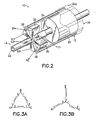
- FIG. 2 is a diagram of the roller or transducer that is the subject matter of the present patent application.
- Figure 3A, 3B are diagrams of a three-phase connection of windings of the roller or transducer in Figure 2.
- Figure 4 is a diagram of a roller system using the roller or transducer in Figure 2.
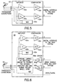
- FIG. 5 is a diagram of a pulse shaper interface circuit used in the roller system in Figure 4.
- Figure 6 is a diagram of a sensor/driver interface circuit used in the roller system in Figure 4.
- Figure 7 is a diagram of a sensor/driver interface circuit used in the roller system in Figure 4.
- Figure 8 is a computer drawn picture of a roller or transducer similar to the one shown in Figure 2.
- Figure 9 is a computer drawn picture of a roller or transducer having an axial coil design.
- Figure 10 is a diagram of an embodiment of a roller or transducer having bearings and a seal that is the subject matter of the present patent application.
- FIGS. 1A, 1B The Basic Invention
- Figures 1A, 1B show the basic invention, which includes a transducer or roller generally indicated as 10 that may be used as a sensor of a force or as a driver for providing a force.
- a transducer or roller generally indicated as 10 that may be used as a sensor of a force or as a driver for providing a force.
- the transducer or roller 10 when used as a sensor, responds to a force F applied by a user, for providing a multi-phase coil signal containing information about the force applied by the user.
- the transducer or roller 10 has a magnetic rotor 12 in combination with a multi-phase coil member 14.
- the magnetic rotor 12 responds to the force F applied by the user, for providing a magnetic rotor force.
- the multi-phase coil member 14 responds to the magnetic rotor force, for providing a multi-phase coil signal containing information about the force F applied by the user.
- the force F applied by the user may include a rotational force applied by the user to a track ball (not shown) or any force applied by the user to a mouse (not shown) that causes the transducer or roller to move or rotate.
- the multi-phase coil signal contains information about the force F applied by the user on the track ball (not shown) or the mouse (not shown).
- the transducer or roller 10 may be used as a part of mobile, office, factory or military equipment, such as a joystick, all now shown.
- the transducer or roller 10 when used as a driver, responds to roller driving signals, for example directly or indirectly from a host system or other electrical circuitry discussed below, for rotating the transducer or roller 10 about a main roller axis.
- the multi-phase coil member 14 responds to the roller driving signals, for providing multi-phase coil driver signals.
- the magnetic rotor 12 responds to the multi-phase coil driver signals, for rotating or moving the transducer or roller 10.
- the transducer or roller 10 shown in Figures 1A, 1B may be used as a sensor or a driver in a roller system in combination with the host system or other electrical circuitry, as discussed below.
- Figure 2 shows the main principle of the roller 10, which includes a tubular shaft 20 that can be rotated around the roller main axis 22 and is attached to a body or frame (not shown) of a device (not shown) having the roller 10 installed therein.
- the tubular shaft 20 has an outside surface for a roller wheel and mechanical support (no bearing shown).
- the magnetic rotor 12 includes a permanent magnet 24 having two permanent magnet extenders 26, 28.
- the tubular shaft 20 has an outside surface 20a for contacting by the user (not shown), a track ball (not shown), a ball (not shown) in a mouse (not shown).
- the multi-phase coil member 14 includes the roller main axis 22 and a three-phase coil 30 arranged thereon.
- the three-phase coil 30 has a ferromagnetic core 32 and three windings indicated as A 1 , A 2 , B 1 , B 2 , C 1 , C 2 .
- the main roller axis 22 is hollow for receiving electrical wires from the windings A 1 , A 2 , B 1 , B 2 , C 1 , C 2 .
- the three windings A 1 , A 2 , B 1 , B 2 , C 1 , C 2 have six ends connected as a delta connection ( Figure 3A) or as a star connection ( Figure 3B).
- the multi-phase coil member 14 may also have four windings for providing four winding signals to be signal processed in order to detect a phase difference therebetween.
- the magnetic rotor 12 rotatably cooperate with the multi-phase coil member 14 via bearings generally positioned in a location indicated by arrow 34.
- the bearings may be a part of the magnetic rotor 12, for rotating the magnetic rotor 12 about the multi-phase coil member 14.
- the bearings may be a part of the multi-phase coil member 14, for rotating the magnetic rotor 12 about the multi-phase coil member 14.
- the bearings may be a separate part of the transducer or roller 10.
- the magnetic rotor 12 conducts the magnetic flux.
- the three-phase coil 30 is attached to the roller main axis 22, and, therefore, it is stable and the wiring is easy to make.
- the three electrical windings A 1 , A 2 , B 1 , B 2 , C 1 , C 2 can be inside the roller main axis 22, protected from the environment.
- the roller 10 tends to stop at positions defined by the magnetic poles of the three-phase coil 30.
- Figures 4-7 show three different ways for connecting the roller 10 to a digital or microprocessor circuit environment.
- Figures 4 and 5 show a first way to connect the roller 10 via transducer connections A, B, C to a simple pulse shaper circuit 50 connected to a central processing unit 52.
- the roller 10 is connected to the microprocessor circuit environment with an active or passive pulse shaping circuit.
- one of the roller lines is connected to a fixed potential, and the remaining two electrical lines are connected to a limiting amplifier 50a, 50b inside the pulse shaper circuit 50.
- the outputs from the limiting amplifier 50a, 50b are provided to comparators 52c, 52d having output lines connected to the central processing unit 52, which is coupled to the host system (not shown).
- the simple pulse shaper circuit 50 also includes a wake-up call circuit (WAC) 52e that starts the functions of the interface circuit that are needed to generate and send digital signals to the host system when the roller is being used; otherwise, the WAC 52e keeps the interface circuit in a shutdown mode to save power.
- WAC wake-up call circuit
- the interface circuit 50 needs an amplifier to guarantee the operation in all reasonable speeds of rotation.
- WAC wake-up circuit
- the WAC 52e can be a separate circuit block or an intrinsic feature of the amplifier.
- the amplifiers 52a, 52b have a high amplification and limit and shape the signal to certain digital signal levels.
- the amplifiers 52a, 52b also act as a comparator, so there are only certain voltage levels in the output of the interface circuit.
- the third line from the roller key transducer is connected to a fixed common potential.
- Figures 4 and 6 show a second way to connect the roller 10 via transducer connections A, B, C to a simple or advanced sensor/driver circuit 60 connected to a central processing unit 62.
- the simple or advanced sensor/driver circuit 60 has limiting and sensing amplifiers 62a, 62b because the same three lines are used for providing roller driver signals to the roller 10.
- the simple or advanced sensor/driver circuit 60 also has comparators 62c, 62d and a wake-up call circuit 62e, similar to that discussed above in relation to Figures 4-5.
- the simple or advanced sensor/driver circuit 60 has an optional limiting or switching circuit 62f to protect the sensing amplifiers 62a, 62b, and the wake-up call circuit 62e during the roller wheel drive; and pulse wave modulation drivers 62g, 62h that receive roller driver signals from the host system (not shown).
- the optional limiting or switching circuit 62f responds to a drive/sense control signal from the host system (not shown) to control whether the roller is in the driver or sensor mode. In operation, the roller 10 will not be driven at the same time when it is being used as a sensor.
- the "driving instructions" from the central processor unit 62 generate signals to the roller lines, and these signals may depend on the position of the roller 10. If the central processing unit (i.e.
- the simple or advanced sensor/driver circuit 60 can have a simpler circuit design.
- the roller driving signals from the central processing unit 62 to the simple or advanced sensor/driver circuit 60 may include a light roller signal, a roller brake signal, a roller step signal, a roller on/off signal, or a combination thereof (as shown).
- the interface circuit 60 in Figure 6 converts the roller signals to proper digital signals and drives the roller circuitry as instructed from the microprocessor circuit environment.
- the instructions can be simply transferred via a few lines. For example, if the user is browsing a list of names in the phone book, when he wants to scroll quickly, and moves the roller quickly, the interface system helps the roller to move. When the user is at the end of the list, the roller brakes and becomes harder to move.
- the roller 10 can also be instructed to step one click at a certain direction or roll by itself at least for demonstration purposes. The roller 10 can also inform the user by vibrating.
- the easiest way to sense and drive using the roller 10 is to perform sensing only, when the driving is inactive. Also, the sensing lines may be protected by the limiting or switching circuit.
- the driving of the roller is made easy by using PWM (Pulse Width Modulation). If the microprocessor unit can use the information of the last state of the signals obtained from the interface, then the interface circuit 60 doesn't need any memory or a state machine.
- sensing/driving circuitry Another possibility is to make the sensing/driving circuitry more complex and have a simpler software design.
- independent timing systems are not needed to the sensing/driving circuit, because the needs of simple timing could be performed otherwise in a microprocessor circuit environment.
- Figures 4 and 7 show a third way to connect the roller 10 via transducer connections A, B, C to a simple or advanced sensor/simple driver circuit 70 and a digital signal processing device 72 connected to a central processing unit 74, for providing full software control with a simple interface circuit, and for providing an amplifier/buffer for voltage and current measurement.
- the simple or advanced sensor/simple driver circuit 70 may have an amplifier (if needed) that gives the signals from the roller 10 to an A/D-converter 72a in the digital signal processor 72.
- the digital signal processor 72 provides the "driving instructions", for example, in a Pulse Width Modulation (PWM) or sigma/delta format. Then only a driver amplifier is needed to supply current to the roller 10.
- the roller driving signals from the central processing unit 72 to the simple or advanced sensor/simple driver circuit 70 may include a first drive signal, a second drive signal, a third drive signal, or a combination thereof.
- the simple or advanced sensor/simple driver circuit 70 has measuring amplifiers 80a, 80b, 80c, 80d, 80e, 80f connected to the transducer lines for voltages and currents in each line.
- the measuring amplifiers 80a, 80b, 80c, 80d, 80e, 80f can be connected using common mode or differential connections. (Common mode: The Currents and voltages are compared to a common reference point. Differential mode: The currents and voltages are measured between the transducer interface lines.) The connection type can be selected depending on the actual case.
- the measuring amplifier outputs are connected to the A/D Converter 72a which converts the signals to digital values.
- the values of the measuring amplifier outputs from the A/D Converter 72a are stored in the memory of the DSP Controller 72 and can be used immediately for knowing the state of the roller 10 in DSP Controller 72.
- the DSP Controller 72 reports to the host system all the variables that need to be known in the host system.
- the host system sends the driving instructions to the DSP Controller 72.
- the DSP Controller 72 makes the drive signals according to the instructions and the state variables of the roller.
- the drive signals (analog or digital, probably PWM in mobile case) are connected to the drive amplifiers or simply drivers 82a, 82b, 82c.
- the drivers 82a, 82b, 82c can be connected using common mode or differential architecture. (But the transducer drive current always uses transducer lines and at least two drivers, one to source and one to sink.)
- the drivers 82a, 82b, 82c are also used for roller click feeling adjustment.
- the WAC 84 wakes the system when the roller 10 is activated by the user.
- the roller 10 can be implemented with full software control (needs signal processing power for roller).
- the number of magnetic steps cannot be controlled, but almost everything else can be, by software.
- the steps can be controlled, but it makes no sense in a portable low-power hand-held device.
- the special interface is only perhaps an integrated amplifier for roller signals and a driver for controlling the feedback. (If the roller is big, it could be used for charging. nowadays big rotating machines can be braked and the energy is supplied back to the network. But it is desirable to have a small roller.) The user can open the roller settings from the menu and control the feeling and behavior in different applications. All the features in the previous paragraph are possible too.
- the best sensing configuration would need analog amplifiers in the sensing lines, not limiting or pulse shape features.
- the analog signals would be sampled and converted to a digital format by an A/D converter. Therefore, the simple DSP controller could have the information of the position (phase), the speed and the acceleration of the roller wheel.
- the driving of the roller could use a full three-phase PWM control. All the characteristics would be software controlled within the boundary conditions.
- the roller 10 can be used as a synchronous generator or motor.
- the interface circuits shown and described above amplifies the three-phase signal and makes proper pulses for the microprocessor.
- the interface circuit can also drive the roller (brake or help its movement or move it up or down).
- the sharing of the functionality between the interface circuitry and the microprocessor environment depends on the amount of digital processing power which is allowed to be used and the amount of software control.
- roller sensing/driving system can be used also with a linear transducer.
- the linear transducer can be useful if the associate movement is linear or less than a full turn and the mechanical shape of the transducer fits well in the application.
- roller of the present invention solve some of the drawbacks of rollers known in the art include:
- Figure 8 shows a computer-rendered drawing of a roller similar to that shown in 2.
- Figure 9 shows a computer-rendered drawing of a roller 100 with an axial coil design generally indicated as 102.
- the coil 102 of the roller or transducer 100 is made in an axial form.
- the coil 102 itself is axial but the air gap between the permanent magnet 24 and the coil 102 can be in a radial construction to avoid axial forces and associated problems with tolerances and the bearings.
- the sensing information is the same as with a three-phase coil, only the phase difference of the signals, compared to each other, is different. In any case, at least three wires are needed to connect the roller transducer coil to the sensing/driving system.
- roller described herein can be made quite small, but ergonomics has to be taken into account also.
- the roller can be made bigger to be used, for example, by disabled persons, children and those having rheumatic pain.
- Figure 10 shows an arrangement having bearings 110 and a seal 112.
- the bearing 110 can be simply a plastic spacer which touches the metallic main roller axis. In heavy duty applications, a ball bearing can be used. In the bearing spacer 110, there is also a space for a seal 112.
- the seal 112 can be made of rubber or teflon, for example.
- the seal 112 material can be used to control damping. The damping has a significant effect on the feeling that the roller has. But to save energy, at least in active use, it may be best to keep the mechanical friction as low as possible and tune the damping and the feeling electrically, for example, by connecting suitable resistive load to roller coils.
- the interface circuit can do that and, therefore, control the roller click feeling.
- Typical applications may include industrial, commercial, medical equipment and military.
- the industrial applications include vehicle user interface (forklift, harvester); industrial equipment user interface (process industry, material handling devices) and robot control.
- the commercial applications may include virtual realty devices (linear transducers for virtual gloves); electronic toys (interactive rotating parts); interactive joystick and mouse; mobile phones and communicators; and electric home appliances (microwave ovens, etc.).
- the medical equipment applications may include a rehabilitation exerciser.
- the military applications may include a sophisticated radar trackball transducer.
- roller or transducer can be mechanically connected to a joystick or other one-, two-or three-dimension systems.
- the linear transducer construction can easily be used for two or three dimensions, because the moving parts (the magnets) can be connected and also integrated into a single moving entity.
Landscapes
- Engineering & Computer Science (AREA)
- General Engineering & Computer Science (AREA)
- Theoretical Computer Science (AREA)
- Human Computer Interaction (AREA)
- Physics & Mathematics (AREA)
- General Physics & Mathematics (AREA)
- Position Input By Displaying (AREA)
- Arrangements For Transmission Of Measured Signals (AREA)
- Control Of Linear Motors (AREA)
Abstract
Description
Claims (36)
- A transducer, comprising:a magnetic rotor, responsive to a force applied by a user, for providing a magnetic rotor force; anda multi-phase coil member, responsive to the magnetic rotor force, for providing a multi-phase coil signal containing information about the force applied by the user.
- A transducer according to claim 1, characterized in that the magnetic rotor includes a permanent magnet having two permanent magnet extenders.
- A transducer according to claim 1, characterized in that the multi-phase coil member includes a tubular shaft having a three-phase coil with a ferromagnetic core and windings.
- A transducer according to claim 3, characterized in that the magnetic rotor is a tubular shaft having an outside surface for contacting by the user.
- A transducer according to claim 1, characterized in that the magnetic rotor has a tubular shaft having an outside surface for contacting by the user.
- A transducer according to claim 1, characterized in that the multi-phase coil member includes windings having electrical wires; and
the multi-phase coil member includes a main roller axis that is hollow for receiving the electrical wires. - A transducer according to claim 1, characterized in that the multi-phase coil member includes three windings having six ends connected as a delta connection.
- A transducer according to claim 1, characterized in that the multi-phase coil member includes three windings having six ends connected as a star connection.
- A transducer according to claim 1, characterized in that the multi-phase coil member has four windings for providing four winding signals to be signal processed in order to detect a phase difference therebetween.
- A transducer according to claim 1, characterized in that the multi-phase coil member responds to roller driving signals from a limiting and sensing amplifier, for providing multi-phase coil driver signals; and
the magnetic rotor responds to the multi-phase coil driver signals, for moving the roller. - A roller system having a roller, the roller comprising:a magnetic rotor, responsive to a force applied by a user, for providing a magnetic rotor force; anda multi-phase coil member, responsive to the magnetic rotor force, for providing a multi-phase coil signal containing information about the force applied by the user.
- A roller system according to claim 11,
characterized in that the roller system further comprises: an pulse shaper circuit having a fixed potential connected to one line of the multi-phase coil member, and having two limiting amplifiers respectively connected to two lines of the multi-phase coil member. - A roller system according to claim 11,
characterized in thatthe multi-phase coil member has three lines;the roller system further comprises: a limiting and sensing amplifier for using the three lines for providing roller driving signals to drive the roller;the multi-phase coil member responds to the roller driving signals, for providing multi-phase coil driver signals; andthe magnetic rotor responds to the multi-phase coil driver signals, for moving the roller. - A roller system according to claim 13,
characterized in that the roller driving signals include a light roller signal, a roller brake signal, a roller step signal, a roller on/off signal, or a combination thereof. - A roller system according to claim 11,
characterized in that
the roller system further comprises: a shaper circuit, a microprocessor for providing software control, and a digital signal processor for providing driving instruction signals to the roller. - A roller system according to claim 11,
characterized in that the roller system further comprises: an interface circuit having a fixed potential connected to one line of the multi-phase coil member, and having two limiting amplifier respectively connected to two lines of the multi-phase coil member. - A roller system according to claim 16,
characterized in that the interface circuit includes two comparators, each for responding to a respective one of the two limiting amplifiers. - A roller system according to claim 11,
characterized in thatthe interface circuit includes a limiting or switching circuit and two pulse wave modulation drivers;the two pulse wave modulation drivers for providing two pulse wave modulation driver signals; andthe interface circuit being connected to the two amplifiers, responding the two pulse wave modulation driver signals, protecting the two amplifiers the driving of the roller, for the two pulse wave modulation driver signals to the roller. - A roller system according to claim 16,
characterized in that the roller system includes a pulse wave modulation driver circuit having a wake-up call circuit; amplifiers and buffers for voltage and current measurement; analog/digital converters for converting analog voltage and current measurement signals into digital voltage and current measurement signals; a digital signal processor for responding to pulse wave modulation driver signals from a host system, for providing driver signals; and pulse wave modulation driver for providing the driver signals to the roller. - A roller for a user interface device such as a mouse or trackball having an element that is moved by a user, comprising:a magnetic rotor, responsive to a force applied by the element that is moved by the user, for providing a magnetic rotor force; anda multi-phase coil member, responsive to the magnetic rotor force, for providing a multi-phase coil signal containing information about the force applied by the element that is moved by the user.
- A roller according to claim 20, characterized in that the magnetic rotor includes a permanent magnet having two permanent magnet extenders.
- A roller according to claim 20, characterized in that the magnetic rotor is a tubular shaft having an outside surface for contacting the element that is rolled by the user.
- A roller according to claim 20,
characterized in that the multi-phase coil member includes a main roller axis that is hollow for receiving the electrical wires. - A roller according to claim 20, characterized in that the information about the force applied by the element that is moved by the user includes information about the amount and direction of movement of the element.
- A roller according to claim 20, characterized in that the multi-phase coil member includes a three-phase connection of windings having a delta formation.
- A roller according to claim 20, characterized in that the multi-phase coil member includes a three-phase connection of windings having a star formation.
- A roller according to claim 20, characterized in that the multi-phase coil member includes four windings for providing four winding signals to be signal processed in order to detect a phase difference therebetween.
- A sensor/driver comprising:a magnetic rotor, responsive to a force applied by a user, for providing a magnetic rotor force, and further responsive to multi-phase coil driver signals, for moving the roller; anda multi-phase coil member, responsive to the magnetic rotor force, for providing a multi-phase coil signal containing information about the force applied by the user, and further responsive to roller driving signals, for providing the multi-phase coil driver signals.
- A sensor/driver according to claim 28,
characterized in that the magnetic rotor includes a permanent magnet having two permanent magnet extenders. - A sensor/driver according to claim 28,
characterized in that the multi-phase coil member includes a tubular shaft having a three-phase coil with a ferromagnetic core and windings. - A sensor/driver according to claim 28,
characterized in thatthe multi-phase coil member includes windings having electrical wires; andthe multi-phase coil member includes a main roller axis that is hollow for receiving the electrical wires. - A sensor/driver according to claim 28,
characterized in that the multi-phase coil member includes three windings having six ends connected as a delta connection. - A sensor/driver according to claim 28,
characterized in that the multi-phase coil member includes three windings having six ends connected as a star connection. - A transducer, comprising:a magnetic rotor, responsive to a force applied by a user, for providing a magnetic rotor flux; anda multi-phase coil member, responsive to the magnetic rotor flux, for providing a multi-phase coil signal containing information about the force applied by the user.
- A transducer according to claim 34,
characterized in that the magnetic rotor includes a permanent magnet having two permanent magnet extenders. - A transducer according to claim 34,
characterized in that the multi-phase coil member includes a tubular shaft having a three-phase coil with a ferromagnetic core and windings.
Applications Claiming Priority (2)
| Application Number | Priority Date | Filing Date | Title |
|---|---|---|---|
| US511755 | 2000-02-24 | ||
| US09/511,755 US6483294B1 (en) | 2000-02-24 | 2000-02-24 | Transducer featuring magnetic rotor concentrically arranged in relation to multi-phase coil |
Publications (2)
| Publication Number | Publication Date |
|---|---|
| EP1128321A2 true EP1128321A2 (en) | 2001-08-29 |
| EP1128321A3 EP1128321A3 (en) | 2003-03-12 |
Family
ID=24036301
Family Applications (1)
| Application Number | Title | Priority Date | Filing Date |
|---|---|---|---|
| EP01301477A Withdrawn EP1128321A3 (en) | 2000-02-24 | 2001-02-20 | A roller device |
Country Status (2)
| Country | Link |
|---|---|
| US (1) | US6483294B1 (en) |
| EP (1) | EP1128321A3 (en) |
Cited By (5)
| Publication number | Priority date | Publication date | Assignee | Title |
|---|---|---|---|---|
| WO2003054782A1 (en) * | 2001-12-21 | 2003-07-03 | Sony Ericsson Mobile Communication Ab | Contactless sensing input device |
| EP1437641A1 (en) * | 2003-01-07 | 2004-07-14 | Universite Des Sciences Et Technologies De Lille | Haptic interface device of the ground-based type comprising at least two separate rotary digital actuators |
| CN100472413C (en) * | 2001-12-21 | 2009-03-25 | 索尼爱立信移动通讯股份有限公司 | Contactless sensing input device and method |
| US8098230B2 (en) | 2004-05-11 | 2012-01-17 | Universite des Sciences et Technologies de Lille Cites Scientifique | Ground-based haptic interface comprising at least two decoupled rotary finger actuators |
| WO2017204425A1 (en) * | 2016-05-26 | 2017-11-30 | 한국전기연구원 | Permanent magnet electrical equipment having non-uniform magnetic pole length |
Families Citing this family (5)
| Publication number | Priority date | Publication date | Assignee | Title |
|---|---|---|---|---|
| CN100342316C (en) * | 2004-06-14 | 2007-10-10 | 精博科技股份有限公司 | Displacement Vector Extraction Device |
| US20060082554A1 (en) * | 2004-10-08 | 2006-04-20 | Motorola, Inc. | Integrated input roller having a rotary mass actuator |
| US20070188454A1 (en) * | 2006-02-15 | 2007-08-16 | Logitech Europe S.A. | Magnetic ratchet for input device roller |
| US20070188453A1 (en) * | 2006-02-15 | 2007-08-16 | Logitech Europe S.A. | Input device roller with hybrid magnetic ratchet system |
| US20120240795A1 (en) * | 2010-12-28 | 2012-09-27 | Agco Corporation | Roller Bale Chute Accumulation |
Family Cites Families (10)
| Publication number | Priority date | Publication date | Assignee | Title |
|---|---|---|---|---|
| US4395711A (en) * | 1980-04-07 | 1983-07-26 | Clarostat Mfg. Co., Inc. | Inductive sensor |
| JPS6142023A (en) * | 1984-08-02 | 1986-02-28 | Nec Corp | Mouse |
| US4626759A (en) | 1985-01-15 | 1986-12-02 | United Technologies Corporation | Low noise differential torquer servo loop and circuitry |
| US4661753A (en) | 1985-01-15 | 1987-04-28 | United Technologies Corporation | Differential torquer |
| US4651130A (en) | 1985-08-28 | 1987-03-17 | United Technologies Corporation | Apparatus and method for retaining phase information for use with a multiple-coil inductive displacement sensor |
| US5489845A (en) * | 1994-09-19 | 1996-02-06 | Ford Motor Company | Encoder system and method for determining absolute rotor position by taking a mid value of the multiple coil output sinusoidal signals |
| US5734370A (en) * | 1995-02-13 | 1998-03-31 | Skodlar; Rafael | Computer control device |
| US5956484A (en) * | 1995-12-13 | 1999-09-21 | Immersion Corporation | Method and apparatus for providing force feedback over a computer network |
| DE19700647C1 (en) | 1997-01-10 | 1998-07-02 | Ericsson Telefon Ab L M | Data entry device |
| JP2001511925A (en) * | 1997-02-12 | 2001-08-14 | カニテック エー/エス | Input device for computer |
-
2000
- 2000-02-24 US US09/511,755 patent/US6483294B1/en not_active Expired - Fee Related
-
2001
- 2001-02-20 EP EP01301477A patent/EP1128321A3/en not_active Withdrawn
Cited By (5)
| Publication number | Priority date | Publication date | Assignee | Title |
|---|---|---|---|---|
| WO2003054782A1 (en) * | 2001-12-21 | 2003-07-03 | Sony Ericsson Mobile Communication Ab | Contactless sensing input device |
| CN100472413C (en) * | 2001-12-21 | 2009-03-25 | 索尼爱立信移动通讯股份有限公司 | Contactless sensing input device and method |
| EP1437641A1 (en) * | 2003-01-07 | 2004-07-14 | Universite Des Sciences Et Technologies De Lille | Haptic interface device of the ground-based type comprising at least two separate rotary digital actuators |
| US8098230B2 (en) | 2004-05-11 | 2012-01-17 | Universite des Sciences et Technologies de Lille Cites Scientifique | Ground-based haptic interface comprising at least two decoupled rotary finger actuators |
| WO2017204425A1 (en) * | 2016-05-26 | 2017-11-30 | 한국전기연구원 | Permanent magnet electrical equipment having non-uniform magnetic pole length |
Also Published As
| Publication number | Publication date |
|---|---|
| US6483294B1 (en) | 2002-11-19 |
| EP1128321A3 (en) | 2003-03-12 |
Similar Documents
| Publication | Publication Date | Title |
|---|---|---|
| US6483294B1 (en) | Transducer featuring magnetic rotor concentrically arranged in relation to multi-phase coil | |
| US8125453B2 (en) | System and method for providing rotational haptic feedback | |
| CN101489717B (en) | Rotary table mounting and drive device | |
| CN101021760A (en) | Input device roller with hybrid magnetic ratchet system | |
| US12032760B2 (en) | Motorized scroll wheel for an input device | |
| US20020105241A1 (en) | Integrated magnetic bearing | |
| CN114257126B (en) | Electromagnetic pulse driver | |
| WO2000070438A1 (en) | Method for pointing out information and a pointing device | |
| WO2007046182A1 (en) | Multiple-rotation absolute-value encoder of geared motor | |
| KR20140078047A (en) | MOTOR AND sensing magnet of THE SAME | |
| CN112454419A (en) | Cooperative robot joint with single encoder | |
| CN107662220A (en) | A kind of joint of mechanical arm and mechanical arm | |
| JP3406886B2 (en) | Device for preventing malfunction of switching circuit in linear motor | |
| US20070188454A1 (en) | Magnetic ratchet for input device roller | |
| CN215093696U (en) | Cooperative robot joint with single encoder | |
| JPH10506467A (en) | Active motion sensor | |
| JP2025069403A (en) | Encoder device, drive device, stage device, and robot device | |
| CN207603394U (en) | A kind of motor of built-in dynamic torque sensing measuring device | |
| JP2023129188A (en) | Force feedback apparatus | |
| GB2347990A (en) | Force feedback device including actuator with moving magnet | |
| CN206663281U (en) | A kind of joint of mechanical arm | |
| EP1456807B1 (en) | Contactless sensing input device | |
| JP3046469B2 (en) | Multi-turn absolute encoder | |
| JP2001004403A (en) | Rotation detecting sensor and electric brake using the sensor | |
| JP4664819B2 (en) | Electric vehicle |
Legal Events
| Date | Code | Title | Description |
|---|---|---|---|
| PUAI | Public reference made under article 153(3) epc to a published international application that has entered the european phase |
Free format text: ORIGINAL CODE: 0009012 |
|
| AK | Designated contracting states |
Kind code of ref document: A2 Designated state(s): AT BE CH CY DE DK ES FI FR GB GR IE IT LI LU MC NL PT SE TR |
|
| AX | Request for extension of the european patent |
Free format text: AL;LT;LV;MK;RO;SI |
|
| RAP1 | Party data changed (applicant data changed or rights of an application transferred) |
Owner name: NOKIA CORPORATION |
|
| PUAL | Search report despatched |
Free format text: ORIGINAL CODE: 0009013 |
|
| AK | Designated contracting states |
Kind code of ref document: A3 Designated state(s): AT BE CH CY DE DK ES FI FR GB GR IE IT LI LU MC NL PT SE TR Designated state(s): AT BE CH CY DE DK ES FI FR GB GR IE IT LI LU MC NL PT SE TR |
|
| AX | Request for extension of the european patent |
Extension state: AL LT LV MK RO SI |
|
| 17P | Request for examination filed |
Effective date: 20030910 |
|
| AKX | Designation fees paid |
Designated state(s): AT BE CH CY DE DK ES FI FR GB GR IE IT LI LU MC NL PT SE TR |
|
| AXX | Extension fees paid |
Extension state: SI Payment date: 20030910 Extension state: RO Payment date: 20030910 Extension state: MK Payment date: 20030910 Extension state: LV Payment date: 20030910 Extension state: LT Payment date: 20030910 Extension state: AL Payment date: 20030910 |
|
| 17Q | First examination report despatched |
Effective date: 20040621 |
|
| STAA | Information on the status of an ep patent application or granted ep patent |
Free format text: STATUS: THE APPLICATION IS DEEMED TO BE WITHDRAWN |
|
| 18D | Application deemed to be withdrawn |
Effective date: 20041103 |