EP1128159A3 - Mechanical shaft with integrated magnet arrangement - Google Patents
Mechanical shaft with integrated magnet arrangement Download PDFInfo
- Publication number
- EP1128159A3 EP1128159A3 EP01102755A EP01102755A EP1128159A3 EP 1128159 A3 EP1128159 A3 EP 1128159A3 EP 01102755 A EP01102755 A EP 01102755A EP 01102755 A EP01102755 A EP 01102755A EP 1128159 A3 EP1128159 A3 EP 1128159A3
- Authority
- EP
- European Patent Office
- Prior art keywords
- der
- ausnehmung
- permanent magnet
- die
- shaft
- Prior art date
- Legal status (The legal status is an assumption and is not a legal conclusion. Google has not performed a legal analysis and makes no representation as to the accuracy of the status listed.)
- Withdrawn
Links
Classifications
-
- G—PHYSICS
- G01—MEASURING; TESTING
- G01D—MEASURING NOT SPECIALLY ADAPTED FOR A SPECIFIC VARIABLE; ARRANGEMENTS FOR MEASURING TWO OR MORE VARIABLES NOT COVERED IN A SINGLE OTHER SUBCLASS; TARIFF METERING APPARATUS; MEASURING OR TESTING NOT OTHERWISE PROVIDED FOR
- G01D5/00—Mechanical means for transferring the output of a sensing member; Means for converting the output of a sensing member to another variable where the form or nature of the sensing member does not constrain the means for converting; Transducers not specially adapted for a specific variable
- G01D5/12—Mechanical means for transferring the output of a sensing member; Means for converting the output of a sensing member to another variable where the form or nature of the sensing member does not constrain the means for converting; Transducers not specially adapted for a specific variable using electric or magnetic means
- G01D5/14—Mechanical means for transferring the output of a sensing member; Means for converting the output of a sensing member to another variable where the form or nature of the sensing member does not constrain the means for converting; Transducers not specially adapted for a specific variable using electric or magnetic means influencing the magnitude of a current or voltage
- G01D5/142—Mechanical means for transferring the output of a sensing member; Means for converting the output of a sensing member to another variable where the form or nature of the sensing member does not constrain the means for converting; Transducers not specially adapted for a specific variable using electric or magnetic means influencing the magnitude of a current or voltage using Hall-effect devices
- G01D5/145—Mechanical means for transferring the output of a sensing member; Means for converting the output of a sensing member to another variable where the form or nature of the sensing member does not constrain the means for converting; Transducers not specially adapted for a specific variable using electric or magnetic means influencing the magnitude of a current or voltage using Hall-effect devices influenced by the relative movement between the Hall device and magnetic fields
-
- G—PHYSICS
- G01—MEASURING; TESTING
- G01D—MEASURING NOT SPECIALLY ADAPTED FOR A SPECIFIC VARIABLE; ARRANGEMENTS FOR MEASURING TWO OR MORE VARIABLES NOT COVERED IN A SINGLE OTHER SUBCLASS; TARIFF METERING APPARATUS; MEASURING OR TESTING NOT OTHERWISE PROVIDED FOR
- G01D2205/00—Indexing scheme relating to details of means for transferring or converting the output of a sensing member
- G01D2205/10—Detecting linear movement
- G01D2205/14—Detecting linear movement by converting the linear movement into a rotary movement
Abstract
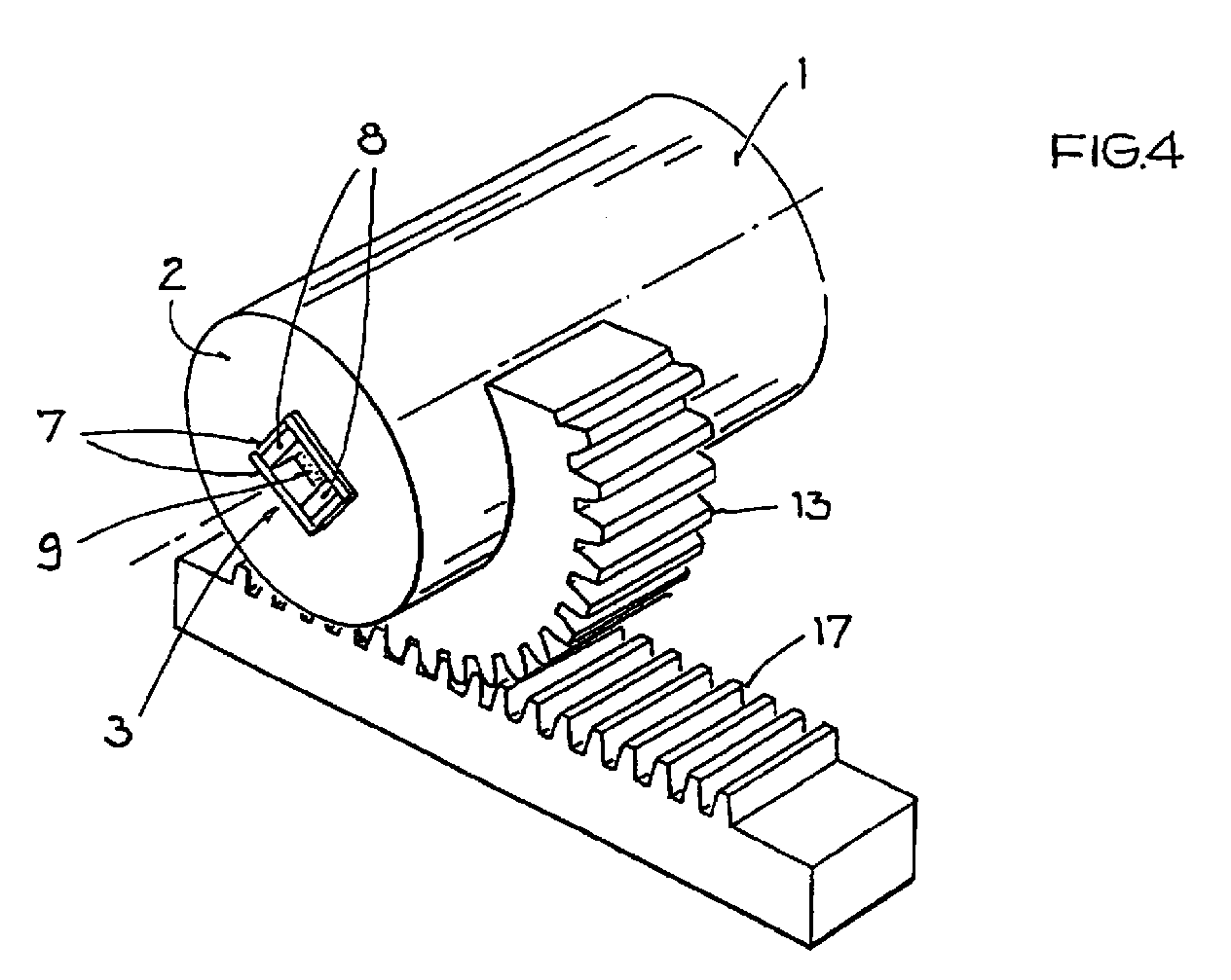
Mechanische Welle (1) mit integrierter Magnetanordnung (8,9) zur Erfassung des Drehwinkels
der Welle (1) um ihre Drehachse mit
Applications Claiming Priority (2)
| Application Number | Priority Date | Filing Date | Title |
|---|---|---|---|
| DE10007968 | 2000-02-22 | ||
| DE10007968A DE10007968C1 (en) | 2000-02-22 | 2000-02-22 | Mechanical shaft with integrated magnet arrangement |
Publications (2)
| Publication Number | Publication Date |
|---|---|
| EP1128159A2 EP1128159A2 (en) | 2001-08-29 |
| EP1128159A3 true EP1128159A3 (en) | 2003-05-07 |
Family
ID=7631792
Family Applications (1)
| Application Number | Title | Priority Date | Filing Date |
|---|---|---|---|
| EP01102755A Withdrawn EP1128159A3 (en) | 2000-02-22 | 2001-02-08 | Mechanical shaft with integrated magnet arrangement |
Country Status (4)
| Country | Link |
|---|---|
| US (1) | US6469502B2 (en) |
| EP (1) | EP1128159A3 (en) |
| JP (1) | JP2001264110A (en) |
| DE (1) | DE10007968C1 (en) |
Families Citing this family (32)
| Publication number | Priority date | Publication date | Assignee | Title |
|---|---|---|---|---|
| JP2002286502A (en) | 2001-03-23 | 2002-10-03 | Aisin Seiki Co Ltd | Displacement sensor |
| US6657346B2 (en) * | 2001-08-24 | 2003-12-02 | Huang Chuan Pan | Device for detecting the rotating speed of a fan motor |
| DE10201141B4 (en) * | 2002-01-15 | 2009-10-15 | Pierburg Gmbh | Stellgetriebe with means for determining the deviation from a predetermined starting position |
| FR2849691B1 (en) * | 2003-01-07 | 2006-12-01 | Electricfil | MAGNETIC SENSOR WITH ROTATING ELEMENT FOR DETERMINING THE LINEAR POSITION OF A MOBILE |
| JP2004271427A (en) * | 2003-03-11 | 2004-09-30 | Matsushita Electric Ind Co Ltd | Rotation angle detector |
| JP4369876B2 (en) | 2004-03-23 | 2009-11-25 | 富士フイルム株式会社 | Silver halide photosensitive material and photothermographic material |
| JP4551698B2 (en) * | 2004-05-28 | 2010-09-29 | 株式会社小松製作所 | Magnetic field forming device and displacement sensor using the same |
| US20060057512A1 (en) | 2004-09-14 | 2006-03-16 | Fuji Photo Film Co., Ltd. | Photothermographic material |
| DE102004056800A1 (en) * | 2004-11-24 | 2006-06-01 | Zf Friedrichshafen Ag | Switching device for a motor vehicle |
| DE102005040647A1 (en) * | 2005-08-27 | 2007-03-08 | Valeo Systèmes d`Essuyage | Electromotive auxiliary drive e.g. windshield wiper drive, for e.g. road vehicle, has permanent magnet provided at shaft extension or at gearing unit, and magnetic sensors provided within bearing arrangement toward shaft axis |
| JP2008051683A (en) * | 2006-08-25 | 2008-03-06 | Ntn Corp | Bearing device for wheel fitted with rotation sensor |
| WO2008106580A1 (en) * | 2007-02-28 | 2008-09-04 | Continental Automotive Systems Us, Inc. | Linear position sensor |
| US10704933B2 (en) * | 2014-09-02 | 2020-07-07 | Infineon Technologies Ag | Integrated angle sensing device |
| US10677617B2 (en) * | 2007-05-30 | 2020-06-09 | Infineon Technologies Ag | Shaft-integrated angle sensing device |
| JP5401902B2 (en) * | 2008-10-03 | 2014-01-29 | 日本電産株式会社 | motor |
| JP5335473B2 (en) * | 2009-02-20 | 2013-11-06 | 光洋電子工業株式会社 | Magnetic encoder |
| DE102010033769A1 (en) * | 2010-08-09 | 2012-02-09 | Valeo Schalter Und Sensoren Gmbh | Device with a torque sensor and a rotation angle sensor |
| DE102010043026A1 (en) * | 2010-10-27 | 2012-05-03 | Endress + Hauser Gmbh + Co. Kg | Electronic device and method for starting up an electronic device |
| JP5944703B2 (en) * | 2012-03-14 | 2016-07-05 | 株式会社ケーヒン | Rotation angle detector |
| US20150160042A1 (en) * | 2013-09-11 | 2015-06-11 | Bourns, Inc. | Devices and methods related to high-resolution multi-turn sensors |
| US10704926B2 (en) * | 2014-09-02 | 2020-07-07 | Infineon Technologies Ag | Shaft-integrated angle sensing device |
| JP2016099190A (en) * | 2014-11-20 | 2016-05-30 | アイシン精機株式会社 | Rotation angle detection device |
| DE102015101246A1 (en) | 2015-01-28 | 2016-07-28 | Fraba B.V. | Magnet-based rotation angle measuring system |
| DE102015101248A1 (en) | 2015-01-28 | 2016-07-28 | Fraba B.V. | Magnet-based rotation angle measuring system |
| AU2016220051A1 (en) * | 2015-02-18 | 2017-08-24 | Willem Den Boer | Pedal-driven vehicle crank |
| DE102016009006B4 (en) * | 2015-07-29 | 2024-01-25 | Infineon Technologies Ag | DRIVE TRAIN OF A MOTOR VEHICLE SYSTEM HAVING A SHAFT-INTEGRATED ANGLE SCANNING DEVICE |
| WO2017088864A1 (en) * | 2015-11-26 | 2017-06-01 | Schaeffler Technologies AG & Co. KG | Encoder and bearing unit having an encoder |
| DE102016100499A1 (en) | 2016-01-13 | 2017-07-13 | Fraba B.V. | Arrangement of a rotation angle measuring system on a housing |
| DE102016002417B4 (en) * | 2016-03-02 | 2017-12-14 | Infineon Technologies Ag | Angle sensor assembly and electric bicycle with such an angle sensor arrangement |
| DE102017104206A1 (en) * | 2016-03-02 | 2017-09-07 | Infineon Technologies Ag | WAVE-INTEGRATED ANGLE MOUNTING ELEMENT |
| DE102016121671B3 (en) * | 2016-11-11 | 2018-03-01 | Samson Aktiengesellschaft | Position sensor and positioner with position sensor |
| EP3730946B1 (en) * | 2019-04-23 | 2023-04-26 | Ningbo Geely Automobile Research & Development Co. Ltd. | Shaft arrangement for a vehicle |
Citations (7)
| Publication number | Priority date | Publication date | Assignee | Title |
|---|---|---|---|---|
| US4121185A (en) * | 1977-07-18 | 1978-10-17 | Illinois Tool Works Inc. | Linear position sensor |
| DE3411773A1 (en) * | 1984-03-30 | 1985-05-23 | Daimler-Benz Ag, 7000 Stuttgart | DEVICE FOR DETECTING THE SPEED AND / OR A TURNING ANGLE OF A SHAFT |
| DE3639208A1 (en) * | 1986-11-15 | 1988-05-19 | Bosch Gmbh Robert | MAGNETORESISTIVE SENSOR FOR DELIVERING ELECTRICAL SIGNALS |
| US5198763A (en) * | 1990-02-20 | 1993-03-30 | Nikkiso Co., Ltd. | Apparatus for monitoring the axial and radial wear on a bearing of a rotary shaft |
| DE4227503A1 (en) * | 1992-08-20 | 1994-02-24 | Vacuumschmelze Gmbh | Permanent magnet system for generating homogeneous field - has single element with variable field direction dependent upon position and produced within controlled field |
| US5679995A (en) * | 1992-08-12 | 1997-10-21 | Seiko Epson Corporation | Permanent magnet rotor of brushless motor |
| US5880586A (en) * | 1994-11-22 | 1999-03-09 | Robert Bosch Gmbh | Apparatus for determining rotational position of a rotatable element without contacting it |
Family Cites Families (3)
| Publication number | Priority date | Publication date | Assignee | Title |
|---|---|---|---|---|
| JPS56107119A (en) * | 1980-01-30 | 1981-08-25 | Nippon Denso Co Ltd | Detecting device for rotational angle |
| GB2188430B (en) * | 1986-03-19 | 1990-01-17 | Honda Motor Co Ltd | Angle-of-rotation sensor |
| DE4014885C2 (en) * | 1989-05-13 | 1995-07-13 | Aisan Ind | Angle of rotation sensor |
-
2000
- 2000-02-22 DE DE10007968A patent/DE10007968C1/en not_active Expired - Fee Related
-
2001
- 2001-02-08 EP EP01102755A patent/EP1128159A3/en not_active Withdrawn
- 2001-02-21 US US09/788,350 patent/US6469502B2/en not_active Expired - Fee Related
- 2001-02-22 JP JP2001047187A patent/JP2001264110A/en active Pending
Patent Citations (7)
| Publication number | Priority date | Publication date | Assignee | Title |
|---|---|---|---|---|
| US4121185A (en) * | 1977-07-18 | 1978-10-17 | Illinois Tool Works Inc. | Linear position sensor |
| DE3411773A1 (en) * | 1984-03-30 | 1985-05-23 | Daimler-Benz Ag, 7000 Stuttgart | DEVICE FOR DETECTING THE SPEED AND / OR A TURNING ANGLE OF A SHAFT |
| DE3639208A1 (en) * | 1986-11-15 | 1988-05-19 | Bosch Gmbh Robert | MAGNETORESISTIVE SENSOR FOR DELIVERING ELECTRICAL SIGNALS |
| US5198763A (en) * | 1990-02-20 | 1993-03-30 | Nikkiso Co., Ltd. | Apparatus for monitoring the axial and radial wear on a bearing of a rotary shaft |
| US5679995A (en) * | 1992-08-12 | 1997-10-21 | Seiko Epson Corporation | Permanent magnet rotor of brushless motor |
| DE4227503A1 (en) * | 1992-08-20 | 1994-02-24 | Vacuumschmelze Gmbh | Permanent magnet system for generating homogeneous field - has single element with variable field direction dependent upon position and produced within controlled field |
| US5880586A (en) * | 1994-11-22 | 1999-03-09 | Robert Bosch Gmbh | Apparatus for determining rotational position of a rotatable element without contacting it |
Also Published As
| Publication number | Publication date |
|---|---|
| JP2001264110A (en) | 2001-09-26 |
| US20010015642A1 (en) | 2001-08-23 |
| EP1128159A2 (en) | 2001-08-29 |
| DE10007968C1 (en) | 2001-08-09 |
| US6469502B2 (en) | 2002-10-22 |
Similar Documents
| Publication | Publication Date | Title |
|---|---|---|
| EP1128159A3 (en) | Mechanical shaft with integrated magnet arrangement | |
| EP1024267A3 (en) | Throttle valve rotation angle sensor | |
| CN2101339U (en) | Brushless motor rotor | |
| EP1316294A3 (en) | Fastener assembly for securing a rod-shaped element in a retaining element connected to a shaft | |
| EP1246513A3 (en) | Variable-strength multipole beamline magnet | |
| EP2009404A3 (en) | Magnetic structure for detecting a relative motion between the magnetic structure and a magnetic field sensor | |
| EP1511154A3 (en) | Fixing permanent magnets onto a rotor body | |
| DE69920794D1 (en) | Electromagnetic proportional valve with variable actuating force, which has a secreted permanent magnet | |
| EP1372251A3 (en) | Linear motor | |
| EP1416607A3 (en) | Spherical airgap electric motor | |
| ATE241763T1 (en) | ACTUATING DEVICE FOR A ROTATING CLOSING PART OF A VALVE | |
| EP0867226A3 (en) | Laboratory centrifuge with electric motor | |
| EP1298362A3 (en) | Shift actuator for a transmission | |
| EP1538727A3 (en) | Brushless electrical machine | |
| EP1777722A3 (en) | Magnetic system for a trip device. | |
| FR2379145A1 (en) | COIL SET FOR NUCLEAR MAGNETIC RESONANCE GYROSCOPES | |
| DE2027783C3 (en) | Polarized micromotor for watches | |
| JP3543148B2 (en) | Linear motor | |
| DE20107117U1 (en) | Braking device with self-generating effect for torsion control | |
| EP1154239A3 (en) | Angular position sensor | |
| EP1193433A3 (en) | Electromagnetic fluid valve | |
| RU2305357C1 (en) | Homogeneous magnetic field inductor | |
| DE1003334B (en) | Electromagnetic oscillating armature motor for alternating current | |
| EP0355262A3 (en) | Device with a cross-wound coil and a rotary magnet | |
| DE20008320U1 (en) | Solenoid valve arrangement |
Legal Events
| Date | Code | Title | Description |
|---|---|---|---|
| PUAI | Public reference made under article 153(3) epc to a published international application that has entered the european phase |
Free format text: ORIGINAL CODE: 0009012 |
|
| 17P | Request for examination filed |
Effective date: 20010208 |
|
| AK | Designated contracting states |
Kind code of ref document: A2 Designated state(s): AT BE CH CY DE DK ES FI FR GB GR IE IT LI LU MC NL PT SE TR |
|
| AX | Request for extension of the european patent |
Free format text: AL;LT;LV;MK;RO;SI |
|
| PUAL | Search report despatched |
Free format text: ORIGINAL CODE: 0009013 |
|
| AK | Designated contracting states |
Designated state(s): AT BE CH CY DE DK ES FI FR GB GR IE IT LI LU MC NL PT SE TR |
|
| AX | Request for extension of the european patent |
Extension state: AL LT LV MK RO SI |
|
| RIC1 | Information provided on ipc code assigned before grant |
Ipc: 7G 01D 5/14 B Ipc: 7G 01B 7/30 A |
|
| AKX | Designation fees paid |
Designated state(s): DE FR GB IT |
|
| STAA | Information on the status of an ep patent application or granted ep patent |
Free format text: STATUS: THE APPLICATION HAS BEEN WITHDRAWN |
|
| 18W | Application withdrawn |
Effective date: 20040326 |