EP1128147A1 - Nosepiece for directing a charge into a furnace - Google Patents
Nosepiece for directing a charge into a furnace Download PDFInfo
- Publication number
- EP1128147A1 EP1128147A1 EP01104290A EP01104290A EP1128147A1 EP 1128147 A1 EP1128147 A1 EP 1128147A1 EP 01104290 A EP01104290 A EP 01104290A EP 01104290 A EP01104290 A EP 01104290A EP 1128147 A1 EP1128147 A1 EP 1128147A1
- Authority
- EP
- European Patent Office
- Prior art keywords
- distal portion
- nosepiece
- charge
- crucible
- transport apparatus
- Prior art date
- Legal status (The legal status is an assumption and is not a legal conclusion. Google has not performed a legal analysis and makes no representation as to the accuracy of the status listed.)
- Granted
Links
- 230000007704 transition Effects 0.000 claims description 28
- 239000003517 fume Substances 0.000 claims description 10
- 239000000463 material Substances 0.000 description 8
- 229910000805 Pig iron Inorganic materials 0.000 description 3
- 229910000831 Steel Inorganic materials 0.000 description 2
- 229910045601 alloy Inorganic materials 0.000 description 2
- 239000000956 alloy Substances 0.000 description 2
- 230000008901 benefit Effects 0.000 description 2
- 238000010276 construction Methods 0.000 description 2
- 230000006698 induction Effects 0.000 description 2
- 239000002184 metal Substances 0.000 description 2
- 229910052751 metal Inorganic materials 0.000 description 2
- 239000007769 metal material Substances 0.000 description 2
- 239000010959 steel Substances 0.000 description 2
- 230000005484 gravity Effects 0.000 description 1
- 238000003780 insertion Methods 0.000 description 1
- 230000037431 insertion Effects 0.000 description 1
- 230000008018 melting Effects 0.000 description 1
- 238000002844 melting Methods 0.000 description 1
- 150000002739 metals Chemical class 0.000 description 1
- 238000012986 modification Methods 0.000 description 1
- 230000004048 modification Effects 0.000 description 1
Images

Classifications
-
- F—MECHANICAL ENGINEERING; LIGHTING; HEATING; WEAPONS; BLASTING
- F27—FURNACES; KILNS; OVENS; RETORTS
- F27D—DETAILS OR ACCESSORIES OF FURNACES, KILNS, OVENS OR RETORTS, IN SO FAR AS THEY ARE OF KINDS OCCURRING IN MORE THAN ONE KIND OF FURNACE
- F27D3/00—Charging; Discharging; Manipulation of charge
-
- F—MECHANICAL ENGINEERING; LIGHTING; HEATING; WEAPONS; BLASTING
- F27—FURNACES; KILNS; OVENS; RETORTS
- F27B—FURNACES, KILNS, OVENS OR RETORTS IN GENERAL; OPEN SINTERING OR LIKE APPARATUS
- F27B14/00—Crucible or pot furnaces
- F27B14/08—Details specially adapted for crucible or pot furnaces
- F27B14/0806—Charging or discharging devices
-
- F—MECHANICAL ENGINEERING; LIGHTING; HEATING; WEAPONS; BLASTING
- F27—FURNACES; KILNS; OVENS; RETORTS
- F27D—DETAILS OR ACCESSORIES OF FURNACES, KILNS, OVENS OR RETORTS, IN SO FAR AS THEY ARE OF KINDS OCCURRING IN MORE THAN ONE KIND OF FURNACE
- F27D3/00—Charging; Discharging; Manipulation of charge
- F27D3/0025—Charging or loading melting furnaces with material in the solid state
-
- F—MECHANICAL ENGINEERING; LIGHTING; HEATING; WEAPONS; BLASTING
- F27—FURNACES; KILNS; OVENS; RETORTS
- F27D—DETAILS OR ACCESSORIES OF FURNACES, KILNS, OVENS OR RETORTS, IN SO FAR AS THEY ARE OF KINDS OCCURRING IN MORE THAN ONE KIND OF FURNACE
- F27D3/00—Charging; Discharging; Manipulation of charge
- F27D2003/0034—Means for moving, conveying, transporting the charge in the furnace or in the charging facilities
- F27D2003/0038—Means for moving, conveying, transporting the charge in the furnace or in the charging facilities comprising shakers
Definitions
- the present invention generally relates to foundry apparatus, and more particularly to apparatus for supplying a charge to a furnace.
- the induction furnace typically comprises an elongate, cylindrical crucible inside which the metal material is melted.
- the furnace must generate high temperatures, on the order of 2500 degrees Fahrenheit or more, to melt the metal, and therefore the inside of the crucible is typically lined with a refractory.
- the metallic material which is added to the furnace is called a charge.
- the charge typically includes steel, pig iron, alloys, and returns.
- the returns typically make up 30 to 50 percent of the charge, and include previously formed members such as runners and gates used in molds.
- the various components of the charge material may be provided in a wide variety of shapes.
- the gates and runners of the returns for example, are often provided in the form of the elongate shafts or bars. Other materials may be provided in generally spherical or arcuate shapes.
- a transport device is typically used to deposit the charge into the crucible.
- a vibratory feeder typically has a hopper portion for receiving the returns, pig iron and other materials to be discharged into the crucible. The vibratory feeder advances the charge toward a front end of the feeder.
- a nosepiece located at the end of the vibratory feeder is positioned over the crucible and defines a chute for directing the charge into the crucible.
- conventional nosepieces typically have an open construction to allow access to the charge in case the charge bridges. It is common, for example, for a conventional nosepiece to have a semi-circular chute.
- the open construction does not limit the distance which the charge material travels away from the vibratory feeder as it is pushed over the chute. As a result, portions of the charge may impact a top edge of the crucible thereby damaging the crucible. The charge also may impact and damage the refractory liner of the crucible.
- transport apparatus for directing a metallic charge into a crucible of a furnace.
- the transport apparatus comprises a hopper for receiving the metallic charge, the hopper having a front end and a rear end.
- a feeder is disposed along a bottom of the hopper and is operable to carry the charge toward the front end of the feeder.
- a nosepiece is attached to the front end of the feeder, the nosepiece having a transition section comprising a downwardly sloped bottom wall and a spout section comprising a sleeve.
- the sleeve defines an enclosed conduit having a proximal portion located nearer the transition section and an opposing distal portion, and the sleeve has an outside diameter sized smaller than a diameter of the crucible.
- a nosepiece for directing a metallic charge into a crucible of a furnace.
- the nosepiece is adapted for attachment to a transport apparatus having a hopper for receiving the metallic charge, the hopper having a front end and a rear end, and a feeder is disposed along a bottom of the hopper and operable to carry the charge toward the front end of the feeder.
- the nosepiece comprises a transition section adapted for attachment to the front end of the transport apparatus, the transition section including spaced first and second side walls, a top wall, and a downwardly sloped bottom wall.
- the nosepiece includes a spout section comprising a sleeve having a proximal portion and a distal portion, the proximal and distal portions of the sleeve defining an enclosed conduit, the sleeve having an outside diameter sized smaller than a diameter of the crucible.
- a nosepiece for directing a metallic charge into a crucible of a furnace.
- the nosepiece is adapted for attachment to a transport apparatus having a hopper for receiving the charge, the hopper having a front end and a rear end, and a feeder disposed along a bottom of the hopper and operable to carry the charge toward the front end of the feeder.
- the nosepiece comprises a transition section adapted for attachment to the front end of the transport apparatus, the transition section including spaced first and second side walls, a top wall, and a downwardly sloped bottom wall.
- the nosepiece also includes a spout section comprising a sleeve having a proximal portion fixed to the transition section and a distal portion pivotably hinged to the transition section.
- the distal portion is movable between a closed position, in which the distal portion engages the proximal portion to from an enclosed conduit, and an open position, in which the distal portion is spaced from the proximal portion.
- the sleeve, in the closed position has an outside diameter sized smaller than a diameter of the crucible
- FIG. 1 is a side elevation view of a nosepiece in accordance with the present invention.
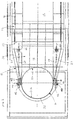
- FIG. 2 is a plan view of the nosepiece in accordance with the present invention.
- a nosepiece in accordance with the present invention is indicated generally with reference numeral 10.
- the nosepiece 10 is shown attached to a transport apparatus 12 adapted for receiving a charge and transporting the charge to the nosepiece 10.
- the nosepiece 10 directs the charge into a crucible 16 of a furnace having a refractory liner 17 (FIG. 1). While, for clarity of illustration, the nosepiece 10 is shown in FIGS. 1 and 2 as incorporated in a specific type of transport apparatus 12, persons of ordinary skill in the art will readily appreciate that the teachings of the invention are no way limited to that apparatus, or to any other particular environment of use. On the contrary, a nosepiece 10 in accordance with the teachings of the present invention may be used with any type of transport apparatus which would benefit from the advantages the nosepiece offers without departing from the scope or spirit of the invention.
- the transport apparatus 12 includes a hopper 18 for receiving the charge.
- the charge may comprise a variety of materials such as steel, pig iron, alloys, and returns.
- the various charge materials are lifted, such as by a suspended magnet (not shown), positioned over the hopper 18, and deposited into the hopper 18.
- the transport apparatus includes a feeder, such as a vibratory feeder floor 19, for advancing the charge from the hopper 18 to a front end 22 of the transport apparatus 12.
- the nosepiece 10 is attached to the front end 22 of the transport apparatus 12.
- the nosepiece 10 comprises a sloped transition section 20 which leads to a spout section 21 for directing the charge into the crucible 16.
- the transition section 20 includes first and second side walls 26, 27, top wall 28, and bottom wall 30 which slopes generally downward from the transport apparatus 12 to the spout section 21.
- the spout section 21 comprises a sleeve 32 which intersects and depends from the bottom wall 30. An outer surface of the sleeve 32 is shaped and sized for insertion into the crucible 16 of the furnace.
- the sleeve 32 has a proximal portion 32a located nearest the transport apparatus 12 and a distal portion 32b located opposite the transport apparatus 12.
- the crucible 16 is cylindrical and has an inside diameter
- the outer surface of the sleeve 32 is also cylindrical and has an outside diameter slightly smaller than the inside diameter of the crucible.
- the lower end of the sleeve 32 may be located slightly above the crucible 16, to provide an enclosed conduit for transporting the charge from the transition section 21 to the crucible 16.
- the charge is deposited into the hopper 18 of the transport apparatus.
- the vibratory feeder 20 advances the charge toward the front end 22 of the transport apparatus 12.
- the sloped bottom wall 30 of the transition section 20 advances the charge toward the spout section 21.
- the sleeve 32 directs the charge into the crucible 16 under the force of gravity. Accordingly, it will be appreciated that the sleeve 32 provides a completely enclosed conduit for directing the charge generally toward a center of the crucible to minimize contact with, and resulting damage to, the refractory liner 17 of the crucible 16.
- the distal portion 32b of the sleeve 32 deflects the charge generally downward and toward a center of the sleeve 32 so that the charge material does not impact a top edge of the crucible 16 or its refractory liner 17.
- the distal portion 32b of the sleeve 32 is movable to allow access into the interior of the nosepiece 10.
- the distal portion 32b of the sleeve 32 is attached by a pair of hinges 40 to the transition section of the nosepiece 10.
- the proximal portion 32a of the sleeve 32 is fixedly attached to the transition section 20.
- Each of the hinges 40 has a stationary member 41 attached to the transition section 20 near an associated side wall 26, 27 and a pivoting member 42 attached to opposite sides of the distal portion 32b.
- the pivoting members 42 pivot about a pivot hinge 43, which allows the distal portion 32b to swing upwardly to allow access to an interior of the nosepiece 10 near the spout section 21.
- the movable distal portion 32b is particularly useful in situations where the charge bridges over the sleeve 32. If bridging occurs, the distal portion 32b may be moved to an open position, as drawn in phantom in FIG. 1, to remove the bridging portions of the charge.
- the outer profile of the distal portion 32b is shaped and sized to allow the distal portion 32b to pivot toward the open position even when the furnace has a fume hood 45 (illustrated in phantom). Subsequently, the distal portion 32b may be closed to once again form a complete spout, thereby precisely directing the charge into the crucible 16 as described above.
- the nosepiece preferably includes a pair of spring-loaded latches 50 positioned near opposing side walls 26, 27 for selectively releasing the distal portion 32b for pivoting to the open position.
- the distal portion 32b includes a pair of vertical supports 52 having a horizontally aligned rod 54 attached to a bottom end.
- a latch body 56 is pivotably secured to the transition section at a pivot point 58, and defines a notch 60 sized to receive a corresponding rod 54.
- a spring 62 is positioned to engage an upper surface of the latch body 56.
- a link 64 has one end attached to a bottom surface of the latch body 56 at an opposite side of the pivot point 58 from the spring 62.
- a second end of the link 64 is attached to a handle 66 which actuates the link 64.
- the spring 62 biases the latch body 56 to pivot so that the notch 60 engages the rod 54, thereby securing the distal portion 32b in the closed position.
- the link 64 pivots the latch body 56 against the force of the spring 62, thereby disengaging the notch 60 from the rod 54.
- the distal portion 32b may then be rotated to the open position.
- the latch body 56 further preferably includes a cam surface 68 which directs the rod 54 into the notch 60 as the distal portion 32b returns to the closed position.
- the present invention brings to the art a new and improved nosepiece for directing a charge into a crucible of a furnace.
- the nosepiece comprises a completely enclosed sleeve which more accurately directs the charge into the crucible.
- the sleeve has a distal portion that deflects the charge toward a center area of the crucible, thereby minimizing impact of the charge on the top edge of the crucible and its refractory liner.
- the nosepiece is split so that the distal portion is movable, thereby to provide access to an interior of the nosepiece. As a result, any bridging in the charge may be addressed by moving the distal portion to an open position.
Landscapes
- Engineering & Computer Science (AREA)
- Mechanical Engineering (AREA)
- General Engineering & Computer Science (AREA)
- Furnace Charging Or Discharging (AREA)
- Crucibles And Fluidized-Bed Furnaces (AREA)
- Chutes (AREA)
- Filling Or Emptying Of Bunkers, Hoppers, And Tanks (AREA)
Abstract
Description
- The present invention generally relates to foundry apparatus, and more particularly to apparatus for supplying a charge to a furnace.
- Foundries often include induction furnaces for melting metals. The induction furnace typically comprises an elongate, cylindrical crucible inside which the metal material is melted. The furnace must generate high temperatures, on the order of 2500 degrees Fahrenheit or more, to melt the metal, and therefore the inside of the crucible is typically lined with a refractory.
- The metallic material which is added to the furnace is called a charge. The charge typically includes steel, pig iron, alloys, and returns. The returns typically make up 30 to 50 percent of the charge, and include previously formed members such as runners and gates used in molds. The various components of the charge material may be provided in a wide variety of shapes. The gates and runners of the returns, for example, are often provided in the form of the elongate shafts or bars. Other materials may be provided in generally spherical or arcuate shapes.
- A transport device is typically used to deposit the charge into the crucible. A vibratory feeder, for example, typically has a hopper portion for receiving the returns, pig iron and other materials to be discharged into the crucible. The vibratory feeder advances the charge toward a front end of the feeder. A nosepiece located at the end of the vibratory feeder is positioned over the crucible and defines a chute for directing the charge into the crucible.
- As the charge is transported toward the front end of the vibratory feeder, the returns and other components of the charge may shift and intertwine such that the charge bridges rather than drops through the chute to the crucible. Accordingly, conventional nosepieces typically have an open construction to allow access to the charge in case the charge bridges. It is common, for example, for a conventional nosepiece to have a semi-circular chute. The open construction, however, does not limit the distance which the charge material travels away from the vibratory feeder as it is pushed over the chute. As a result, portions of the charge may impact a top edge of the crucible thereby damaging the crucible. The charge also may impact and damage the refractory liner of the crucible. The materials and labor required to replace a refractory liner often costs on the order of $10,000.00 or more. In addition, the furnace is not available for use during refractory replacement, which typically takes 3-5 days, resulting in a significant amount of down time for the furnace. Accordingly, there is a need for a nosepiece which accurately deposits a charge into a crucible without damaging the crucible.
- In accordance with certain aspects of the present invention, transport apparatus for directing a metallic charge into a crucible of a furnace is provided. The transport apparatus comprises a hopper for receiving the metallic charge, the hopper having a front end and a rear end. A feeder is disposed along a bottom of the hopper and is operable to carry the charge toward the front end of the feeder. A nosepiece is attached to the front end of the feeder, the nosepiece having a transition section comprising a downwardly sloped bottom wall and a spout section comprising a sleeve. The sleeve defines an enclosed conduit having a proximal portion located nearer the transition section and an opposing distal portion, and the sleeve has an outside diameter sized smaller than a diameter of the crucible.
- In accordance with additional aspects of the present invention, a nosepiece is provided for directing a metallic charge into a crucible of a furnace. The nosepiece is adapted for attachment to a transport apparatus having a hopper for receiving the metallic charge, the hopper having a front end and a rear end, and a feeder is disposed along a bottom of the hopper and operable to carry the charge toward the front end of the feeder. The nosepiece comprises a transition section adapted for attachment to the front end of the transport apparatus, the transition section including spaced first and second side walls, a top wall, and a downwardly sloped bottom wall. The nosepiece includes a spout section comprising a sleeve having a proximal portion and a distal portion, the proximal and distal portions of the sleeve defining an enclosed conduit, the sleeve having an outside diameter sized smaller than a diameter of the crucible.
- In accordance with still further aspects of the present invention, a nosepiece is provided for directing a metallic charge into a crucible of a furnace. The nosepiece is adapted for attachment to a transport apparatus having a hopper for receiving the charge, the hopper having a front end and a rear end, and a feeder disposed along a bottom of the hopper and operable to carry the charge toward the front end of the feeder. The nosepiece comprises a transition section adapted for attachment to the front end of the transport apparatus, the transition section including spaced first and second side walls, a top wall, and a downwardly sloped bottom wall. The nosepiece also includes a spout section comprising a sleeve having a proximal portion fixed to the transition section and a distal portion pivotably hinged to the transition section. The distal portion is movable between a closed position, in which the distal portion engages the proximal portion to from an enclosed conduit, and an open position, in which the distal portion is spaced from the proximal portion. The sleeve, in the closed position, has an outside diameter sized smaller than a diameter of the crucible
- FIG. 1 is a side elevation view of a nosepiece in accordance with the present invention.
- FIG. 2 is a plan view of the nosepiece in accordance with the present invention.
- Referring to FIGS. 1 and 2, a nosepiece in accordance with the present invention is indicated generally with
reference numeral 10. Thenosepiece 10 is shown attached to atransport apparatus 12 adapted for receiving a charge and transporting the charge to thenosepiece 10. Thenosepiece 10 directs the charge into a crucible 16 of a furnace having a refractory liner 17 (FIG. 1). While, for clarity of illustration, thenosepiece 10 is shown in FIGS. 1 and 2 as incorporated in a specific type oftransport apparatus 12, persons of ordinary skill in the art will readily appreciate that the teachings of the invention are no way limited to that apparatus, or to any other particular environment of use. On the contrary, anosepiece 10 in accordance with the teachings of the present invention may be used with any type of transport apparatus which would benefit from the advantages the nosepiece offers without departing from the scope or spirit of the invention. - As illustrated in FIGS. 1 and 2, the
transport apparatus 12 includes a hopper 18 for receiving the charge. The charge may comprise a variety of materials such as steel, pig iron, alloys, and returns. The various charge materials are lifted, such as by a suspended magnet (not shown), positioned over the hopper 18, and deposited into the hopper 18. The transport apparatus includes a feeder, such as avibratory feeder floor 19, for advancing the charge from the hopper 18 to a front end 22 of thetransport apparatus 12. - The
nosepiece 10 is attached to the front end 22 of thetransport apparatus 12. Thenosepiece 10 comprises asloped transition section 20 which leads to aspout section 21 for directing the charge into thecrucible 16. Thetransition section 20 includes first andsecond side walls top wall 28, andbottom wall 30 which slopes generally downward from thetransport apparatus 12 to thespout section 21. Thespout section 21 comprises asleeve 32 which intersects and depends from thebottom wall 30. An outer surface of thesleeve 32 is shaped and sized for insertion into thecrucible 16 of the furnace. - As best shown in FIG. 2, the
sleeve 32 has aproximal portion 32a located nearest thetransport apparatus 12 and adistal portion 32b located opposite thetransport apparatus 12. In the preferred embodiment, thecrucible 16 is cylindrical and has an inside diameter, and the outer surface of thesleeve 32 is also cylindrical and has an outside diameter slightly smaller than the inside diameter of the crucible. As a result, the lower end of thesleeve 32 may be located slightly above thecrucible 16, to provide an enclosed conduit for transporting the charge from thetransition section 21 to thecrucible 16. - In operation, the charge is deposited into the hopper 18 of the transport apparatus. The
vibratory feeder 20 advances the charge toward the front end 22 of thetransport apparatus 12. The slopedbottom wall 30 of thetransition section 20 advances the charge toward thespout section 21. Thesleeve 32 directs the charge into thecrucible 16 under the force of gravity. Accordingly, it will be appreciated that thesleeve 32 provides a completely enclosed conduit for directing the charge generally toward a center of the crucible to minimize contact with, and resulting damage to, therefractory liner 17 of thecrucible 16. More specifically, thedistal portion 32b of thesleeve 32 deflects the charge generally downward and toward a center of thesleeve 32 so that the charge material does not impact a top edge of thecrucible 16 or itsrefractory liner 17. - In accordance with additional aspects of the present invention, the
distal portion 32b of thesleeve 32 is movable to allow access into the interior of thenosepiece 10. As best shown in FIGS. 1 and 2, thedistal portion 32b of thesleeve 32 is attached by a pair ofhinges 40 to the transition section of thenosepiece 10. According to the illustrated embodiment, theproximal portion 32a of thesleeve 32 is fixedly attached to thetransition section 20. Each of thehinges 40 has astationary member 41 attached to thetransition section 20 near an associatedside wall member 42 attached to opposite sides of thedistal portion 32b. The pivotingmembers 42 pivot about apivot hinge 43, which allows thedistal portion 32b to swing upwardly to allow access to an interior of thenosepiece 10 near thespout section 21. - The movable
distal portion 32b is particularly useful in situations where the charge bridges over thesleeve 32. If bridging occurs, thedistal portion 32b may be moved to an open position, as drawn in phantom in FIG. 1, to remove the bridging portions of the charge. The outer profile of thedistal portion 32b is shaped and sized to allow thedistal portion 32b to pivot toward the open position even when the furnace has a fume hood 45 (illustrated in phantom). Subsequently, thedistal portion 32b may be closed to once again form a complete spout, thereby precisely directing the charge into thecrucible 16 as described above. - The nosepiece preferably includes a pair of spring-loaded latches 50 positioned near opposing
side walls distal portion 32b for pivoting to the open position. As best shown in Fig. 1, thedistal portion 32b includes a pair ofvertical supports 52 having a horizontally alignedrod 54 attached to a bottom end. Alatch body 56 is pivotably secured to the transition section at apivot point 58, and defines anotch 60 sized to receive a correspondingrod 54. Aspring 62 is positioned to engage an upper surface of thelatch body 56. Alink 64 has one end attached to a bottom surface of thelatch body 56 at an opposite side of thepivot point 58 from thespring 62. A second end of thelink 64 is attached to ahandle 66 which actuates thelink 64. - In a normal position, the
spring 62 biases thelatch body 56 to pivot so that thenotch 60 engages therod 54, thereby securing thedistal portion 32b in the closed position. When thehandle 66 is rotated, thelink 64 pivots thelatch body 56 against the force of thespring 62, thereby disengaging thenotch 60 from therod 54. Thedistal portion 32b may then be rotated to the open position. Thelatch body 56 further preferably includes a cam surface 68 which directs therod 54 into thenotch 60 as thedistal portion 32b returns to the closed position. - In view of the foregoing, it will be appreciated that the present invention brings to the art a new and improved nosepiece for directing a charge into a crucible of a furnace. The nosepiece comprises a completely enclosed sleeve which more accurately directs the charge into the crucible. The sleeve has a distal portion that deflects the charge toward a center area of the crucible, thereby minimizing impact of the charge on the top edge of the crucible and its refractory liner. In addition, the nosepiece is split so that the distal portion is movable, thereby to provide access to an interior of the nosepiece. As a result, any bridging in the charge may be addressed by moving the distal portion to an open position.
- The foregoing detailed description has been given for clearness of understanding only, and no unnecessary limitations should be understood therefrom, as modifications would be obvious to those skilled in the art.
Claims (19)
- A nosepiece for directing a metallic charge into a crucible of a furnace, the nosepiece adapted for attachment to a transport apparatus having a hopper for receiving the charge, the hopper having a front end and a rear end, and a feeder disposed along a bottom of the hopper and operable to carry the charge toward the front end of the feeder, the nosepiece comprising:a transition section adapted for attachment to the front end of the transport apparatus, the transition section including spaced first and second side walls, a top wall, and a downwardly sloped bottom wall; anda spout section comprising a sleeve having a proximal portion fixed to the transition section and a distal portion pivotably hinged to the transition section, the distal portion being movable between a closed position, in which the distal portion engages the proximal portion to from an enclosed conduit, and an open position, in which the distal portion is spaced from the proximal portion, the sleeve, in the closed position, having an outside diameter sized smaller than a diameter of the crucible.
- The nosepiece of claim 1, further comprising a spring-loaded latch adapted to engage and secure the distal portion in the closed position, the spring-loaded latch being releasable to disengage from the distal portion, thereby allowing the distal portion to move to the open position.
- The nosepiece of claim 1, in which the furnace includes a fume hood extending over the crucible, and in which the nosepiece is sized to fit inside the fume hood.
- The nosepiece of claim 3, in which the distal portion has an outside profile shaped and sized to allow the distal portion to pivot to the open position inside the fume hood.
- The nosepiece of claim 1, in which the metallic charge comprises returns.
- Transport apparatus for directing a metallic charge into a crucible of a furnace, the transport apparatus comprising:a hopper for receiving the metallic charge, the hopper having a front end and a rear end;a feeder disposed along a bottom of the hopper and operable to carry the charge toward the front end of the feeder; anda nosepiece attached to the front end of the feeder, the nosepiece having a transition section comprising a downwardly sloped bottom wall and a spout section comprising a sleeve, the sleeve defining an enclosed conduit having a proximal portion located nearer the transition section and an opposing distal portion, and the sleeve having an outside diameter sized smaller than a diameter of the crucible.
- The transport apparatus of claim 6, in which the distal portion is movably attached to the transition section, the distal portion movable between a closed position, in which the distal portion engages the proximal portion to form the enclosed conduit, and an open position, in which the distal portion is spaced from the proximal portion.
- The transport apparatus of claim 7, in which a hinge connects the distal portion to the transition section, wherein the hinge allows the distal portion to pivot between the open and closed positions.
- The transport apparatus of claim 7, further comprising a spring-loaded latch adapted to engage and secure the distal portion in the closed position, the spring-loaded latch being releasable to disengage from the distal portion, thereby allowing the distal portion to move to the open position.
- The transport apparatus of claim 7, in which the furnace includes a fume hood extending over the crucible, and in which the nosepiece is sized to fit inside the fume hood.
- The transport apparatus of claim 10, in which the distal portion has an outside profile shaped and sized to allow the distal portion to pivot to the open position inside the fume hood.
- The transport apparatus of claim 6, in which the metallic charge comprises returns.
- A nosepiece for directing a metallic charge into a crucible of a furnace, the nosepiece adapted for attachment to a transport apparatus having a hopper for receiving the charge, the hopper having a front end and a rear end, and a feeder disposed along a bottom of the hopper and operable to carry the charge toward the front end of the feeder, the nosepiece comprising:a transition section adapted for attachment to the front end of the transport apparatus, the transition section including spaced first and second side walls, a top wall, and a downwardly sloped bottom wall; anda spout section comprising a sleeve having a proximal portion and a distal portion, the proximal and distal portions of the sleeve defining an enclosed conduit, the sleeve having an outside diameter sized smaller than a diameter of the crucible.
- The nosepiece of claim 13, in which the distal portion of the sleeve is movably attached to the transition section, the distal portion being movable between a closed position, in which the distal portion engages the proximal portion to form the enclosed conduit, and an open position, in which the distal portion is spaced from the proximal portion.
- The nosepiece of claim 14, in which a hinge connects the distal portion to the transition section, wherein the hinge allows the distal portion to pivot between the open and closed positions.
- The nosepiece of claim 14, further comprising a spring-loaded latch adapted to engage and secure the distal portion in the closed position, the spring-loaded latch being releasable to disengage from the distal portion, thereby allowing the distal portion to move to the open position.
- The nosepiece of claim 14, in which the furnace includes a fume hood extending over the crucible, and in which the nosepiece is sized to fit inside the fume hood.
- The nosepiece of claim 17, in which the distal portion has an outside profile shaped and sized to allow the distal portion to pivot to the open position inside the fume hood.
- The nosepiece of claim 13, in which the metallic charge comprises returns.
Applications Claiming Priority (2)
| Application Number | Priority Date | Filing Date | Title |
|---|---|---|---|
| US09/507,817 US6306337B1 (en) | 2000-02-22 | 2000-02-22 | Nosepiece for directing a charge into a furnace |
| US507817 | 2000-02-22 |
Publications (2)
| Publication Number | Publication Date |
|---|---|
| EP1128147A1 true EP1128147A1 (en) | 2001-08-29 |
| EP1128147B1 EP1128147B1 (en) | 2005-12-28 |
Family
ID=24020258
Family Applications (1)
| Application Number | Title | Priority Date | Filing Date |
|---|---|---|---|
| EP01104290A Expired - Lifetime EP1128147B1 (en) | 2000-02-22 | 2001-02-22 | Nosepiece for directing a charge into a furnace |
Country Status (7)
| Country | Link |
|---|---|
| US (1) | US6306337B1 (en) |
| EP (1) | EP1128147B1 (en) |
| JP (1) | JP2001294311A (en) |
| AU (1) | AU781756B2 (en) |
| BR (1) | BR0100696A (en) |
| CA (1) | CA2337648C (en) |
| DE (1) | DE60116159T2 (en) |
Citations (5)
| Publication number | Priority date | Publication date | Assignee | Title |
|---|---|---|---|---|
| DE1433858A1 (en) * | 1964-01-28 | 1968-11-21 | Loeschke Kg Hartzerkleinerungs | Shaft furnace hood, especially for shaft furnaces for burning cement, dolomite, magnesite and the like. |
| US4579524A (en) * | 1983-11-09 | 1986-04-01 | General Kinematics Corporation | Charge forming preheating apparatus and method |
| US4606530A (en) * | 1984-03-28 | 1986-08-19 | Victor Litchinko | Installation and process for continuously charging a reactor with solid material and heating said material with the gases emitted from said reactor |
| US5213200A (en) * | 1992-03-25 | 1993-05-25 | Inductotherm Corp. | Vibratory flow feed conveyor with removable pan |
| GB2289936A (en) * | 1994-05-27 | 1995-12-06 | Ea Tech Ltd | Electric melting furnace with pressure actuated discharge |
Family Cites Families (5)
| Publication number | Priority date | Publication date | Assignee | Title |
|---|---|---|---|---|
| US3390872A (en) * | 1966-05-31 | 1968-07-02 | Koppers Co Inc | Scrap metal preheater |
| US4023784A (en) * | 1974-12-23 | 1977-05-17 | Wallace Henry J | Apparatus for feeding metal scrap into molten metal |
| US4211316A (en) * | 1978-12-28 | 1980-07-08 | Pullman Berry Company | Chute for charging steel making vessels |
| US4690638A (en) * | 1985-08-06 | 1987-09-01 | Yamaguchikyoei Industry Co. Ltd. | Water cooled scrap preheating bucket |
| AT395656B (en) * | 1990-11-19 | 1993-02-25 | Voest Alpine Ind Anlagen | SYSTEM FOR THE PRODUCTION OF LIQUID METALS |
-
2000
- 2000-02-22 US US09/507,817 patent/US6306337B1/en not_active Expired - Fee Related
-
2001
- 2001-02-20 CA CA002337648A patent/CA2337648C/en not_active Expired - Fee Related
- 2001-02-20 AU AU23144/01A patent/AU781756B2/en not_active Ceased
- 2001-02-21 BR BR0100696-7A patent/BR0100696A/en not_active IP Right Cessation
- 2001-02-22 DE DE60116159T patent/DE60116159T2/en not_active Expired - Fee Related
- 2001-02-22 EP EP01104290A patent/EP1128147B1/en not_active Expired - Lifetime
- 2001-02-22 JP JP2001046241A patent/JP2001294311A/en not_active Withdrawn
Patent Citations (5)
| Publication number | Priority date | Publication date | Assignee | Title |
|---|---|---|---|---|
| DE1433858A1 (en) * | 1964-01-28 | 1968-11-21 | Loeschke Kg Hartzerkleinerungs | Shaft furnace hood, especially for shaft furnaces for burning cement, dolomite, magnesite and the like. |
| US4579524A (en) * | 1983-11-09 | 1986-04-01 | General Kinematics Corporation | Charge forming preheating apparatus and method |
| US4606530A (en) * | 1984-03-28 | 1986-08-19 | Victor Litchinko | Installation and process for continuously charging a reactor with solid material and heating said material with the gases emitted from said reactor |
| US5213200A (en) * | 1992-03-25 | 1993-05-25 | Inductotherm Corp. | Vibratory flow feed conveyor with removable pan |
| GB2289936A (en) * | 1994-05-27 | 1995-12-06 | Ea Tech Ltd | Electric melting furnace with pressure actuated discharge |
Also Published As
| Publication number | Publication date |
|---|---|
| DE60116159T2 (en) | 2006-06-29 |
| CA2337648C (en) | 2009-05-19 |
| AU2314401A (en) | 2001-08-23 |
| US6306337B1 (en) | 2001-10-23 |
| BR0100696A (en) | 2001-10-09 |
| EP1128147B1 (en) | 2005-12-28 |
| JP2001294311A (en) | 2001-10-23 |
| CA2337648A1 (en) | 2001-08-22 |
| DE60116159D1 (en) | 2006-02-02 |
| AU781756B2 (en) | 2005-06-09 |
Similar Documents
| Publication | Publication Date | Title |
|---|---|---|
| US11358539B2 (en) | Transportation container | |
| US6435864B2 (en) | Door assembly for rotary furnace | |
| US6306337B1 (en) | Nosepiece for directing a charge into a furnace | |
| EP0160185B1 (en) | Tiltable metallurgical furnace vessel | |
| CZ173796A3 (en) | Filling device for supplying molten metal in an electric furnace | |
| US3047916A (en) | Container-tilting rigging | |
| US4156452A (en) | Furnaces | |
| CN102271838A (en) | Molten metal treatment facility, molten metal treatment method, and molten metal transport line using same | |
| JP4390472B2 (en) | Melting furnace feeder | |
| CN102575902B (en) | Movable sweat hearth for metal melting furnace | |
| JP4065983B2 (en) | Ladle with lid | |
| US2209153A (en) | Apparatus for treating metals | |
| US3212653A (en) | Apparatus for charging open-hearth furnaces | |
| NL8200418A (en) | METHOD FOR OPERATING A RIDING MIXER AND USES THEREOF | |
| US682512A (en) | Open-hearth steel-furnace. | |
| JPS6147631B2 (en) | ||
| US5164146A (en) | Foundry furnace having outlet flow passage | |
| JP2002126866A (en) | Molten steel pot lid | |
| JP2906402B2 (en) | Detachable trolley for horizontal ladle | |
| BR112020003576B1 (en) | METHOD FOR LOADING A PRE-PACKAGED CHARGE INTO A METALLURGICAL OR REFINING FURNACE, AND, PRE-PACKAGED CHARGE FOR BEING UNLOADED INTO A METALLURGICAL OR REFINING FURNACE | |
| US3860060A (en) | Ladle maintenance safety cage | |
| JP2855870B2 (en) | Injection method of scrap lump in metallurgical furnace | |
| SU802366A1 (en) | Ladle for slag melt | |
| US776133A (en) | Apparatus for handling material in glass-houses. | |
| JP3029337U (en) | Dross receiving device |
Legal Events
| Date | Code | Title | Description |
|---|---|---|---|
| PUAI | Public reference made under article 153(3) epc to a published international application that has entered the european phase |
Free format text: ORIGINAL CODE: 0009012 |
|
| AK | Designated contracting states |
Kind code of ref document: A1 Designated state(s): CH DE FR GB IT LI Kind code of ref document: A1 Designated state(s): AT BE CH CY DE DK ES FI FR GB GR IE IT LI LU MC NL PT SE TR |
|
| AX | Request for extension of the european patent |
Free format text: AL;LT;LV;MK;RO;SI |
|
| 17P | Request for examination filed |
Effective date: 20020130 |
|
| AKX | Designation fees paid |
Free format text: CH DE FR GB IT LI |
|
| 17Q | First examination report despatched |
Effective date: 20040218 |
|
| GRAP | Despatch of communication of intention to grant a patent |
Free format text: ORIGINAL CODE: EPIDOSNIGR1 |
|
| GRAS | Grant fee paid |
Free format text: ORIGINAL CODE: EPIDOSNIGR3 |
|
| GRAA | (expected) grant |
Free format text: ORIGINAL CODE: 0009210 |
|
| AK | Designated contracting states |
Kind code of ref document: B1 Designated state(s): CH DE FR GB IT LI |
|
| REG | Reference to a national code |
Ref country code: GB Ref legal event code: FG4D |
|
| REG | Reference to a national code |
Ref country code: CH Ref legal event code: EP |
|
| REG | Reference to a national code |
Ref country code: CH Ref legal event code: NV Representative=s name: E. BLUM & CO. PATENTANWAELTE |
|
| REF | Corresponds to: |
Ref document number: 60116159 Country of ref document: DE Date of ref document: 20060202 Kind code of ref document: P |
|
| ET | Fr: translation filed | ||
| PLBE | No opposition filed within time limit |
Free format text: ORIGINAL CODE: 0009261 |
|
| STAA | Information on the status of an ep patent application or granted ep patent |
Free format text: STATUS: NO OPPOSITION FILED WITHIN TIME LIMIT |
|
| 26N | No opposition filed |
Effective date: 20060929 |
|
| REG | Reference to a national code |
Ref country code: CH Ref legal event code: PFA Owner name: GENERAL KINEMATICS CORPORATION Free format text: GENERAL KINEMATICS CORPORATION#777 LAKE ZURICH ROAD, P.O. BOX 2010#BARRINGTON, ILLINOIS 60011 (US) -TRANSFER TO- GENERAL KINEMATICS CORPORATION#777 LAKE ZURICH ROAD, P.O. BOX 2010#BARRINGTON, ILLINOIS 60011 (US) |
|
| PGFP | Annual fee paid to national office [announced via postgrant information from national office to epo] |
Ref country code: DE Payment date: 20090219 Year of fee payment: 9 |
|
| PGFP | Annual fee paid to national office [announced via postgrant information from national office to epo] |
Ref country code: CH Payment date: 20090224 Year of fee payment: 9 Ref country code: GB Payment date: 20090219 Year of fee payment: 9 |
|
| PGFP | Annual fee paid to national office [announced via postgrant information from national office to epo] |
Ref country code: IT Payment date: 20090223 Year of fee payment: 9 |
|
| PGFP | Annual fee paid to national office [announced via postgrant information from national office to epo] |
Ref country code: FR Payment date: 20090220 Year of fee payment: 9 |
|
| REG | Reference to a national code |
Ref country code: CH Ref legal event code: PL |
|
| GBPC | Gb: european patent ceased through non-payment of renewal fee |
Effective date: 20100222 |
|
| PG25 | Lapsed in a contracting state [announced via postgrant information from national office to epo] |
Ref country code: LI Free format text: LAPSE BECAUSE OF NON-PAYMENT OF DUE FEES Effective date: 20100228 Ref country code: CH Free format text: LAPSE BECAUSE OF NON-PAYMENT OF DUE FEES Effective date: 20100228 |
|
| REG | Reference to a national code |
Ref country code: FR Ref legal event code: ST Effective date: 20101029 |
|
| PG25 | Lapsed in a contracting state [announced via postgrant information from national office to epo] |
Ref country code: FR Free format text: LAPSE BECAUSE OF NON-PAYMENT OF DUE FEES Effective date: 20100301 |
|
| PG25 | Lapsed in a contracting state [announced via postgrant information from national office to epo] |
Ref country code: DE Free format text: LAPSE BECAUSE OF NON-PAYMENT OF DUE FEES Effective date: 20100901 |
|
| PG25 | Lapsed in a contracting state [announced via postgrant information from national office to epo] |
Ref country code: IT Free format text: LAPSE BECAUSE OF NON-PAYMENT OF DUE FEES Effective date: 20100222 Ref country code: GB Free format text: LAPSE BECAUSE OF NON-PAYMENT OF DUE FEES Effective date: 20100222 |