EP1128059A2 - Fuel injector filter unit having a composite housing - Google Patents
Fuel injector filter unit having a composite housing Download PDFInfo
- Publication number
- EP1128059A2 EP1128059A2 EP01200571A EP01200571A EP1128059A2 EP 1128059 A2 EP1128059 A2 EP 1128059A2 EP 01200571 A EP01200571 A EP 01200571A EP 01200571 A EP01200571 A EP 01200571A EP 1128059 A2 EP1128059 A2 EP 1128059A2
- Authority
- EP
- European Patent Office
- Prior art keywords
- ferrule
- fuel injector
- filter unit
- overlying
- inlet tube
- Prior art date
- Legal status (The legal status is an assumption and is not a legal conclusion. Google has not performed a legal analysis and makes no representation as to the accuracy of the status listed.)
- Granted
Links
Images
Classifications
-
- F—MECHANICAL ENGINEERING; LIGHTING; HEATING; WEAPONS; BLASTING
- F02—COMBUSTION ENGINES; HOT-GAS OR COMBUSTION-PRODUCT ENGINE PLANTS
- F02M—SUPPLYING COMBUSTION ENGINES IN GENERAL WITH COMBUSTIBLE MIXTURES OR CONSTITUENTS THEREOF
- F02M61/00—Fuel-injectors not provided for in groups F02M39/00 - F02M57/00 or F02M67/00
- F02M61/16—Details not provided for in, or of interest apart from, the apparatus of groups F02M61/02 - F02M61/14
- F02M61/165—Filtering elements specially adapted in fuel inlets to injector
-
- F—MECHANICAL ENGINEERING; LIGHTING; HEATING; WEAPONS; BLASTING
- F02—COMBUSTION ENGINES; HOT-GAS OR COMBUSTION-PRODUCT ENGINE PLANTS
- F02M—SUPPLYING COMBUSTION ENGINES IN GENERAL WITH COMBUSTIBLE MIXTURES OR CONSTITUENTS THEREOF
- F02M37/00—Apparatus or systems for feeding liquid fuel from storage containers to carburettors or fuel-injection apparatus; Arrangements for purifying liquid fuel specially adapted for, or arranged on, internal-combustion engines
- F02M37/22—Arrangements for purifying liquid fuel specially adapted for, or arranged on, internal-combustion engines, e.g. arrangements in the feeding system
- F02M37/32—Arrangements for purifying liquid fuel specially adapted for, or arranged on, internal-combustion engines, e.g. arrangements in the feeding system characterised by filters or filter arrangements
-
- Y—GENERAL TAGGING OF NEW TECHNOLOGICAL DEVELOPMENTS; GENERAL TAGGING OF CROSS-SECTIONAL TECHNOLOGIES SPANNING OVER SEVERAL SECTIONS OF THE IPC; TECHNICAL SUBJECTS COVERED BY FORMER USPC CROSS-REFERENCE ART COLLECTIONS [XRACs] AND DIGESTS
- Y10—TECHNICAL SUBJECTS COVERED BY FORMER USPC
- Y10S—TECHNICAL SUBJECTS COVERED BY FORMER USPC CROSS-REFERENCE ART COLLECTIONS [XRACs] AND DIGESTS
- Y10S239/00—Fluid sprinkling, spraying, and diffusing
- Y10S239/23—Screens
-
- Y—GENERAL TAGGING OF NEW TECHNOLOGICAL DEVELOPMENTS; GENERAL TAGGING OF CROSS-SECTIONAL TECHNOLOGIES SPANNING OVER SEVERAL SECTIONS OF THE IPC; TECHNICAL SUBJECTS COVERED BY FORMER USPC CROSS-REFERENCE ART COLLECTIONS [XRACs] AND DIGESTS
- Y10—TECHNICAL SUBJECTS COVERED BY FORMER USPC
- Y10T—TECHNICAL SUBJECTS COVERED BY FORMER US CLASSIFICATION
- Y10T137/00—Fluid handling
- Y10T137/794—With means for separating solid material from the fluid
- Y10T137/8085—Hollow strainer, fluid inlet and outlet perpendicular to each other
Definitions
- the present invention relates to a filter, and more particularly a fuel injector filter having a composite housing including a plastic body that is reinforced with a metal ferrule.
- the fuel filter also provides a retaining feature preventing axial dislocation of an O-ring surrounding the fuel injector and sealingly connecting the fuel injector to a fuel supply.
- a fuel filter to remove particulate matter and impurities from a fuel used in a conventional fuel injector assembly.
- the use of a fuel filter is believed to increase the efficiency of an engine using the fuel injector assembly, as well as to decrease the production of undesired exhaust.
- These fuel filters are often attached to an inlet tube of the fuel injector assembly by a manufacturing process known as Astaking.@ The fuel filter must be precisely aligned before attachment to the fuel injector assembly. Thus, the manufacturing process of the fuel injector assembly is laborious and expensive. Further, the attached fuel filter may not be easily removed from the fuel filter assembly.
- the present invention provides a filter unit for an inlet tube of a fuel injector.
- the inlet tube has an inside surface, an outside surface, and an annular end surface extending between the inside and outside surfaces.
- the filter unit includes a filter mesh defining a flow area.
- a body directs fuel flow through the flow area.
- the body has a first portion adapted for overlying the inside surface, a second portion adapted for overlying the annular end surface, and a third portion adapted for overlying the outside surface.
- a ferrule reinforces the body.
- the ferrule has a first part contiguously engaging the first portion of the body, a second part contiguously engaging the second portion of the body, and a third part contiguously engaging the third portion of the body.
- the present invention further provides a fuel injector including an inlet tube having an inside surface, an outside surface, and an annular end surface extending between the inside and outside surfaces.
- a filter unit includes a filter mesh defining a flow area.
- a body directs fuel flow through the flow area. The body has a first portion overlying the inside surface, a second portion overlying the annular end surface, and a third portion overlying the outside surface.
- a ferrule reinforces the body. The ferrule has a first part contiguously engaging the first portion of the body, a second part contiguously engaging the second portion of the body, and a third part contiguously engaging the third portion of the body.
- the present invention also provides a method of manufacturing a filter unit for an inlet tube of a fuel injector.
- a filter mesh defining a flow area is provided.
- a ferrule having a first part adapted for overlying the inside surface, a second part adapted for overlying the annular end surface, and a third part adapted for overlying the outside surface is provided.
- a body to connect the filter mesh and the ferrule is molded, the body directing the fuel flow through the flow area.
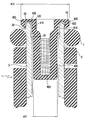
- the figure is a cross-sectional view showing an upper end of a fuel injector and a filter according to the present invention.
- the figure is a cross-sectional view showing a fuel injector 1 comprising an inlet tube 3 encircled by an overmold 5.
- An O-ring 7 sealingly connects the fuel injector 1 to a fuel supply such as a fuel rail (not shown).
- a fuel filter unit 10 according to the present invention is shown disposed within a fuel injector inlet tube 3.
- the fuel injector inlet tube 3 includes an inside surface 31, an outside surface 33, and an annular end surface 35 extending between the inside and outside surfaces 31, 33, respectively.
- the fuel injector inlet tube 3 may be disposed within a variety of conventional fuel injector assemblies, including top feed fuel injectors and bottom feed fuel injectors, for example.
- the fuel filter unit 10 includes a filter body 400, a ferrule 600, and a filter mesh 800.
- the filter mesh 800 defines a flow area through the fuel filter unit 10.
- the filter mesh 800 may be constructed from a variety of materials, including metals such as stainless steel and plastics or the like, having filter mesh orifices of a variety of sizes.
- the filter mesh 800 is 40 Fm nylon mesh.
- the filter body 400 has a first portion 410, a second portion 420, and a third portion 430.
- the first portion 410 is adapted for overlying the inside surface 31 of the fuel injector inlet tube 3.
- the first portion 410 of the filter body 400 extends between an interior perimeter defining a minimum cross-sectional size and an exterior perimeter defining a maximum cross-sectional size.
- the second portion 420 is adapted for overlying the annular end surface 35 of the fuel injector inlet tube 3.
- the third portion 430 is adapted for overlying the outside surface 33 of the fuel injector inlet tube 3.
- the filter body 400 directs fuel flow through the flow area of the filter mesh 800.
- the filter body 400 may be constructed from a variety of materials, including plastics or the like.
- the filter body is constructed of a plastic material.
- the filter body 400 is constructed of 6/6 or 6/12 35% glass filled nylon.
- the ferrule 600 includes a first part 610, a second part 620, and a third part 630.
- the ferrule 600 is adapted to substantially reinforce the filter body 400.
- the ferrule 600 is adapted to be interposed between the fuel filter body 400 and the fuel injector inlet tube 3.
- the first part 610 of the ferrule 600 is adapted to contiguously engage the first portion 410 of the filter body 400 and the inside surface 31 of the fuel injector inlet tube 3.
- the first part 610 of the ferrule 600 defines a mouth having a cross-sectional size that is smaller than the maximum cross-sectional size of the exterior perimeter 413 and is larger than the minimum cross-sectional size of the interior perimeter 411 of the filter body 400.
- the second part 620 of the ferrule 600 is adapted to contiguously engage the second portion 420 of the filter body 400 and the annular end surface 35 of the fuel injector inlet tube 3.
- the third part 630 of the ferrule 600 is adapted to contiguously engage the third portion 430 of the filter body 400 and the outside surface 33 of the fuel injector inlet tube 3.
- the ferrule 600 may be constructed from a variety of materials, including metals such as stainless steel and brass or the like.
- the ferrule 600 is constructed from a metal material, such as brass and/or stainless steel.
- the ferrule 600 is constructed from type 7030 alloy 260 brass.
- the modulus of elasticity of the ferrule 600 is substantially greater than the modulus of elasticity of the filter body 400.
- the third portion 430 of the filter body 400 extends above the outside surface 33 of the fuel injector inlet tube 3.
- a groove for retaining the O-ring 7 is defined by the third portion 430, the inlet tube 3, and the overmold 5.
Landscapes
- Engineering & Computer Science (AREA)
- Chemical & Material Sciences (AREA)
- Combustion & Propulsion (AREA)
- Mechanical Engineering (AREA)
- General Engineering & Computer Science (AREA)
- Fuel-Injection Apparatus (AREA)
Abstract
Description
Claims (16)
- A filter unit for an inlet tube of a fuel injector, the inlet tube having an inside surface, an outside surface, and an annular end surface extending between the inside and outside surfaces, the filter unit comprising:a filter mesh defining a flow area;a body directing fuel flow through the flow area, the body having a first portion adapted for overlying the inside surface, a second portion adapted for overlying the annular end surface, and a third portion adapted for overlying the outside surface; anda ferrule reinforcing the body, the ferrule having a first part contiguously engaging the first portion of the body, a second part contiguously engaging the second portion of the body, and a third part contiguously engaging the third portion of the body.
- The filter unit according to claim 1, wherein the ferrule is adapted to be interposed between the body and the inlet tube.
- The filter unit according to claim 1, wherein the ferrule is adapted to contiguously engage the inside, annular end, and outside surfaces of the inlet tube.
- The filter unit according to claim 1, wherein first portion of the body extends between an interior perimeter and an exterior perimeter, and wherein the first part of the ferrule defines a mouth having a cross-sectional size that is smaller than a maximum cross-section size defined by the exterior perimeter and larger than a minimum cross-section size defined by the interior perimeter.
- The filter unit according to claim 1, wherein the body has a greater modulus of elasticity relative to the ferrule.
- The filter unit according to claim 1, wherein the body is a plastic material and the ferrule is a metal material.
- The filter unit according to claim 6, wherein the plastic material is nylon, and the metal material is selected from a group consisting of brass and stainless steel.
- A fuel injector comprising:an inlet tube having an inside surface, an outside surface, and an annular end surface extending between the inside and outside surfaces;a filter unit including a filter mesh defining a flow area;a body directing fuel flow through the flow area, the body having a first portion overlying the inside surface, a second portion overlying the annular end surface, and a third portion overlying the outside surface; anda ferrule reinforcing the body, the ferrule having a first part contiguously engaging the first portion of the body, a second part contiguously engaging the second portion of the body, and a third part contiguously engaging the third portion of the body.
- The fuel injector according to claim 8, wherein the ferrule is interposed between the body and the inlet tube, and contiguously engages the inside, annular end, and outside surfaces of the inlet tube.
- The fuel injector according to claim 8, wherein first portion of the body extends between an interior perimeter and an exterior perimeter, and wherein the first part of the ferrule defines a mouth having a cross-sectional size that is smaller than a maximum cross-section size defined by the exterior perimeter and larger than a minimum cross-section size defined by the interior perimeter.
- The fuel injector according to claim 8, wherein the body has a greater modulus of elasticity relative to the ferrule.
- The fuel injector according to claim 8, wherein the body is a plastic material and the ferrule is a metal material.
- The fuel injector according to claim 12, wherein the plastic material is nylon, and the metal material is selected from a group consisting of brass and stainless steel.
- The fuel injector according to claim 8, further comprising:an overmold encircling the outside surface; andan O-ring retained in a groove defined by the third portion, the outside surface, and the overmold.
- A method of manufacturing a filter unit for an inlet tube of a fuel injector, the method comprising:providing a filter mesh defining a flow area;providing a ferrule having a first part adapted for overlying the inside surface, a second part adapted for overlying the annular end surface, and a third part adapted for overlying the outside surface; andmolding a body to connect the filter mesh and the ferrule, the body directing the fuel flow through the flow area.
- The method according to claim 15, wherein the providing the ferrule includes forming the first part so as to define a mouth defining a first cross-sectional size, and wherein the molding the body includes forming a first portion having an interior perimeter and an exterior perimeter, the interior perimeter defining a second cross-sectional size smaller than the first cross-sectional size, and the exterior perimeter defining a third cross-section size larger than the first cross-sectional size.
Applications Claiming Priority (2)
| Application Number | Priority Date | Filing Date | Title |
|---|---|---|---|
| US511273 | 2000-02-23 | ||
| US09/511,273 US6199775B1 (en) | 2000-02-23 | 2000-02-23 | Fuel injector filter unit having a composite housing |
Publications (3)
| Publication Number | Publication Date |
|---|---|
| EP1128059A2 true EP1128059A2 (en) | 2001-08-29 |
| EP1128059A3 EP1128059A3 (en) | 2003-07-02 |
| EP1128059B1 EP1128059B1 (en) | 2006-08-02 |
Family
ID=24034186
Family Applications (1)
| Application Number | Title | Priority Date | Filing Date |
|---|---|---|---|
| EP01200571A Expired - Lifetime EP1128059B1 (en) | 2000-02-23 | 2001-02-19 | Fuel injector filter unit having a composite housing |
Country Status (4)
| Country | Link |
|---|---|
| US (1) | US6199775B1 (en) |
| EP (1) | EP1128059B1 (en) |
| JP (1) | JP2001234833A (en) |
| DE (1) | DE60121843T2 (en) |
Cited By (1)
| Publication number | Priority date | Publication date | Assignee | Title |
|---|---|---|---|---|
| DE10334785A1 (en) * | 2003-07-30 | 2005-02-24 | Robert Bosch Gmbh | Fuel injection valve and method for its assembly |
Families Citing this family (12)
| Publication number | Priority date | Publication date | Assignee | Title |
|---|---|---|---|---|
| EP1296057B1 (en) * | 2001-09-19 | 2011-01-05 | Filtertek Inc. | Integrated fuel filter and calibration tube for a fuel injector |
| JP2005226557A (en) * | 2004-02-13 | 2005-08-25 | Denso Corp | Fuel injection valve |
| JP2006249959A (en) * | 2005-03-09 | 2006-09-21 | Denso Corp | Fuel injection valve |
| US7617991B2 (en) * | 2006-03-31 | 2009-11-17 | Delphi Technologies, Inc. | Injector fuel filter with built-in orifice for flow restriction |
| EP2000662B1 (en) * | 2007-06-04 | 2012-03-14 | Continental Automotive GmbH | Adjusting and filter arrangement for an injection valve and injection valve |
| US9777859B2 (en) * | 2012-11-19 | 2017-10-03 | Continental Automotive Systems, Inc. | Purging and sealing-reductant delivery unit for selective catalytic reduction systems |
| DE102013101703A1 (en) * | 2013-02-21 | 2014-08-21 | Borgwarner Beru Systems Gmbh | Evaporator |
| EP2811152B1 (en) * | 2013-06-04 | 2018-04-18 | Continental Automotive GmbH | Filter for a fluid injection valve, fluid injection valve and method for producing a filter for a fluid injection valve |
| US9458808B1 (en) * | 2014-12-15 | 2016-10-04 | Brunswick Corporation | Marine propulsion devices and fuel injection systems for marine propulsion devices |
| DE102015217673A1 (en) | 2015-09-15 | 2017-03-16 | Continental Automotive Gmbh | Injection device for metering a fluid and motor vehicle with such an injection device |
| US10502112B2 (en) * | 2017-09-14 | 2019-12-10 | Vitesco Technologies USA, LLC | Injector for reductant delivery unit having fluid volume reduction assembly |
| US10947880B2 (en) | 2018-02-01 | 2021-03-16 | Continental Powertrain USA, LLC | Injector for reductant delivery unit having fluid volume reduction assembly |
Family Cites Families (14)
| Publication number | Priority date | Publication date | Assignee | Title |
|---|---|---|---|---|
| IT214896Z2 (en) | 1988-10-28 | 1990-07-04 | Weber Srl | FEEDING DEVICE OF AN INTERNAL COMBUSTION ENGINE PROVIDED WITH A PERFECTED FILTER ELEMENT |
| US4946107A (en) | 1988-11-29 | 1990-08-07 | Pacer Industries, Inc. | Electromagnetic fuel injection valve |
| DE4131535A1 (en) * | 1991-09-21 | 1993-03-25 | Bosch Gmbh Robert | ELECTROMAGNETICALLY OPERATED INJECTION VALVE |
| US5335863A (en) * | 1993-05-03 | 1994-08-09 | Siemens Automotive L.P. | Filter cartridge mounting for a top-feed fuel injector |
| JPH06323221A (en) * | 1993-05-13 | 1994-11-22 | Nippon Injector Kk | Fuel injection valve |
| DE4325842A1 (en) | 1993-07-31 | 1995-02-02 | Bosch Gmbh Robert | Fuel injection valve |
| US5356079A (en) | 1993-11-23 | 1994-10-18 | Siemens Automotive L.P. | Fuel injector snap-lock filter-retainer |
| US5641126A (en) * | 1995-05-19 | 1997-06-24 | Siemens Automotive Corporation | Fuel injection systems with compact filter mountings |
| US5704553A (en) | 1995-10-30 | 1998-01-06 | Wieczorek; David P. | Compact injector armature valve assembly |
| JP3338614B2 (en) | 1996-06-03 | 2002-10-28 | 愛三工業株式会社 | Fuel injection valve |
| JP2824761B2 (en) * | 1996-06-07 | 1998-11-18 | 株式会社ケーヒン | Filter in fuel injection valve |
| DE19629589B4 (en) | 1996-07-23 | 2007-08-30 | Robert Bosch Gmbh | Fuel injector |
| DE19647587A1 (en) * | 1996-11-18 | 1998-05-20 | Bosch Gmbh Robert | Fuel injector |
| JPH11173244A (en) * | 1997-12-08 | 1999-06-29 | Toray Ind Inc | Filter for injector |
-
2000
- 2000-02-23 US US09/511,273 patent/US6199775B1/en not_active Expired - Lifetime
-
2001
- 2001-02-19 DE DE60121843T patent/DE60121843T2/en not_active Expired - Lifetime
- 2001-02-19 EP EP01200571A patent/EP1128059B1/en not_active Expired - Lifetime
- 2001-02-21 JP JP2001045243A patent/JP2001234833A/en active Pending
Cited By (2)
| Publication number | Priority date | Publication date | Assignee | Title |
|---|---|---|---|---|
| DE10334785A1 (en) * | 2003-07-30 | 2005-02-24 | Robert Bosch Gmbh | Fuel injection valve and method for its assembly |
| US7770812B2 (en) | 2003-07-30 | 2010-08-10 | Robert Bosch Gmbh | Fuel injector and method for its installation |
Also Published As
| Publication number | Publication date |
|---|---|
| DE60121843D1 (en) | 2006-09-14 |
| DE60121843T2 (en) | 2007-08-30 |
| JP2001234833A (en) | 2001-08-31 |
| US6199775B1 (en) | 2001-03-13 |
| EP1128059A3 (en) | 2003-07-02 |
| EP1128059B1 (en) | 2006-08-02 |
Similar Documents
| Publication | Publication Date | Title |
|---|---|---|
| US6199775B1 (en) | Fuel injector filter unit having a composite housing | |
| CA2404247C (en) | Integrated fuel filter and calibration tube for a fuel injector | |
| EP0755485B1 (en) | Discrete filter mounted in fuel rail | |
| US6936168B2 (en) | Fuel strainer assembly | |
| KR101355984B1 (en) | High pressure nozzle and method of manufacturing the high pressure nozzle | |
| US6998043B2 (en) | Fuel strainer assembly | |
| CN110529307A (en) | Watertight aircase with Integral filtering medium | |
| CN103977639B (en) | Housing, the method being installed to from the device and housing of air separation fluid on joint | |
| US4430213A (en) | Ultrafiltration unit | |
| US5725621A (en) | Filter end cap attachment | |
| US6846412B2 (en) | Combination filter assembly | |
| EP1063415A3 (en) | Fuel injector and method of assembling a fuel injector | |
| EP0989072A3 (en) | Wide-mouth container made of synthetic resin and method of manufacturing pressure resistant wide-mouth container | |
| EP1190884A3 (en) | Fuel filler pipe | |
| US6183544B1 (en) | Air filter with reinforced pressure tap | |
| US6561769B1 (en) | Filter and muffler for a vacuum pump | |
| EP0752263A1 (en) | Filter end cap attachment | |
| CN1460792A (en) | Fuel oil spraying valve | |
| US6758191B2 (en) | Vehicle intake manifold having an integrated fuel rail and volume adjacent thereto | |
| JP2005083231A (en) | Fuel filter | |
| JPH10299667A (en) | Casing pot for containing liquid feed pump | |
| CN208138072U (en) | A kind of diesel fuel filter filter core with degassing function | |
| EP1106819A2 (en) | Filter for pressure regulator | |
| EP3496836A1 (en) | Diesel fuel pre-filtering system | |
| CN222752829U (en) | A portable ash filter |
Legal Events
| Date | Code | Title | Description |
|---|---|---|---|
| PUAI | Public reference made under article 153(3) epc to a published international application that has entered the european phase |
Free format text: ORIGINAL CODE: 0009012 |
|
| AK | Designated contracting states |
Kind code of ref document: A2 Designated state(s): AT BE CH CY DE DK ES FI FR GB GR IE IT LI LU MC NL PT SE TR |
|
| AX | Request for extension of the european patent |
Free format text: AL;LT;LV;MK;RO;SI |
|
| PUAL | Search report despatched |
Free format text: ORIGINAL CODE: 0009013 |
|
| AK | Designated contracting states |
Designated state(s): AT BE CH CY DE DK ES FI FR GB GR IE IT LI LU MC NL PT SE TR |
|
| AX | Request for extension of the european patent |
Extension state: AL LT LV MK RO SI |
|
| RAP1 | Party data changed (applicant data changed or rights of an application transferred) |
Owner name: SIEMENS VDO AUTOMOTIVE CORPORATION |
|
| 17P | Request for examination filed |
Effective date: 20031212 |
|
| AKX | Designation fees paid |
Designated state(s): DE FR GB IT |
|
| 17Q | First examination report despatched |
Effective date: 20050309 |
|
| GRAP | Despatch of communication of intention to grant a patent |
Free format text: ORIGINAL CODE: EPIDOSNIGR1 |
|
| GRAS | Grant fee paid |
Free format text: ORIGINAL CODE: EPIDOSNIGR3 |
|
| GRAA | (expected) grant |
Free format text: ORIGINAL CODE: 0009210 |
|
| AK | Designated contracting states |
Kind code of ref document: B1 Designated state(s): DE FR GB IT |
|
| PG25 | Lapsed in a contracting state [announced via postgrant information from national office to epo] |
Ref country code: IT Free format text: LAPSE BECAUSE OF FAILURE TO SUBMIT A TRANSLATION OF THE DESCRIPTION OR TO PAY THE FEE WITHIN THE PRESCRIBED TIME-LIMIT;WARNING: LAPSES OF ITALIAN PATENTS WITH EFFECTIVE DATE BEFORE 2007 MAY HAVE OCCURRED AT ANY TIME BEFORE 2007. THE CORRECT EFFECTIVE DATE MAY BE DIFFERENT FROM THE ONE RECORDED. Effective date: 20060802 |
|
| REG | Reference to a national code |
Ref country code: GB Ref legal event code: FG4D |
|
| REF | Corresponds to: |
Ref document number: 60121843 Country of ref document: DE Date of ref document: 20060914 Kind code of ref document: P |
|
| EN | Fr: translation not filed | ||
| PLBE | No opposition filed within time limit |
Free format text: ORIGINAL CODE: 0009261 |
|
| STAA | Information on the status of an ep patent application or granted ep patent |
Free format text: STATUS: NO OPPOSITION FILED WITHIN TIME LIMIT |
|
| 26N | No opposition filed |
Effective date: 20070503 |
|
| GBPC | Gb: european patent ceased through non-payment of renewal fee |
Effective date: 20070219 |
|
| PG25 | Lapsed in a contracting state [announced via postgrant information from national office to epo] |
Ref country code: GB Free format text: LAPSE BECAUSE OF NON-PAYMENT OF DUE FEES Effective date: 20070219 Ref country code: FR Free format text: LAPSE BECAUSE OF FAILURE TO SUBMIT A TRANSLATION OF THE DESCRIPTION OR TO PAY THE FEE WITHIN THE PRESCRIBED TIME-LIMIT Effective date: 20070511 |
|
| PG25 | Lapsed in a contracting state [announced via postgrant information from national office to epo] |
Ref country code: FR Free format text: LAPSE BECAUSE OF FAILURE TO SUBMIT A TRANSLATION OF THE DESCRIPTION OR TO PAY THE FEE WITHIN THE PRESCRIBED TIME-LIMIT Effective date: 20060802 |
|
| PGFP | Annual fee paid to national office [announced via postgrant information from national office to epo] |
Ref country code: DE Payment date: 20160229 Year of fee payment: 16 |
|
| REG | Reference to a national code |
Ref country code: DE Ref legal event code: R119 Ref document number: 60121843 Country of ref document: DE |
|
| PG25 | Lapsed in a contracting state [announced via postgrant information from national office to epo] |
Ref country code: DE Free format text: LAPSE BECAUSE OF NON-PAYMENT OF DUE FEES Effective date: 20170901 |