EP1128054A2 - Pressure balancing metering subassembly for use with a modular egr valve - Google Patents
Pressure balancing metering subassembly for use with a modular egr valve Download PDFInfo
- Publication number
- EP1128054A2 EP1128054A2 EP01200543A EP01200543A EP1128054A2 EP 1128054 A2 EP1128054 A2 EP 1128054A2 EP 01200543 A EP01200543 A EP 01200543A EP 01200543 A EP01200543 A EP 01200543A EP 1128054 A2 EP1128054 A2 EP 1128054A2
- Authority
- EP
- European Patent Office
- Prior art keywords
- metering
- poppet
- pressure
- piston
- subassembly
- Prior art date
- Legal status (The legal status is an assumption and is not a legal conclusion. Google has not performed a legal analysis and makes no representation as to the accuracy of the status listed.)
- Withdrawn
Links
Images


Classifications
-
- F—MECHANICAL ENGINEERING; LIGHTING; HEATING; WEAPONS; BLASTING
- F02—COMBUSTION ENGINES; HOT-GAS OR COMBUSTION-PRODUCT ENGINE PLANTS
- F02M—SUPPLYING COMBUSTION ENGINES IN GENERAL WITH COMBUSTIBLE MIXTURES OR CONSTITUENTS THEREOF
- F02M26/00—Engine-pertinent apparatus for adding exhaust gases to combustion-air, main fuel or fuel-air mixture, e.g. by exhaust gas recirculation [EGR] systems
- F02M26/65—Constructional details of EGR valves
- F02M26/66—Lift valves, e.g. poppet valves
- F02M26/67—Pintles; Spindles; Springs; Bearings; Sealings; Connections to actuators
-
- F—MECHANICAL ENGINEERING; LIGHTING; HEATING; WEAPONS; BLASTING
- F02—COMBUSTION ENGINES; HOT-GAS OR COMBUSTION-PRODUCT ENGINE PLANTS
- F02M—SUPPLYING COMBUSTION ENGINES IN GENERAL WITH COMBUSTIBLE MIXTURES OR CONSTITUENTS THEREOF
- F02M26/00—Engine-pertinent apparatus for adding exhaust gases to combustion-air, main fuel or fuel-air mixture, e.g. by exhaust gas recirculation [EGR] systems
- F02M26/52—Systems for actuating EGR valves
- F02M26/53—Systems for actuating EGR valves using electric actuators, e.g. solenoids
-
- F—MECHANICAL ENGINEERING; LIGHTING; HEATING; WEAPONS; BLASTING
- F02—COMBUSTION ENGINES; HOT-GAS OR COMBUSTION-PRODUCT ENGINE PLANTS
- F02M—SUPPLYING COMBUSTION ENGINES IN GENERAL WITH COMBUSTIBLE MIXTURES OR CONSTITUENTS THEREOF
- F02M26/00—Engine-pertinent apparatus for adding exhaust gases to combustion-air, main fuel or fuel-air mixture, e.g. by exhaust gas recirculation [EGR] systems
- F02M26/13—Arrangement or layout of EGR passages, e.g. in relation to specific engine parts or for incorporation of accessories
- F02M26/40—Arrangement or layout of EGR passages, e.g. in relation to specific engine parts or for incorporation of accessories with timing means in the recirculation passage, e.g. cyclically operating valves or regenerators; with arrangements involving pressure pulsations
Definitions
- the present invention relates to exhaust gas recirculation valves for use with internal combustion engines.
- Exhaust gas recirculation (EGR) valves capture engine exhaust and recycle at least a portion of that captured exhaust gas into the combustion chamber of the engine to improve combustion.
- Exhaust gas is used since it is readily available and contains only a small amount of oxygen. Adding the exhaust gas to the air in the combustion chamber has the effect of lowering the combustion temperature below the point at which nitrogen combines with oxygen. Thus, exhaust gas recirculation increases fuel economy and reduces the level of undesirable emissions.
- EGR valves include an actuator and a metering base.
- the metering base includes a metering chamber having a metering port.
- the metering chamber has an end that is associated with the intake manifold or intake vacuum of the engine.
- the metering port is connected to a source of exhaust gas and provides a passageway for the flow of exhaust gas into the metering chamber.
- An elongate shaft extends contiguously in a longitudinal direction from the actuator, through an orifice in the metering base, into the metering chamber, and to the metering port.
- a metering poppet which is a plunger-shaped member, is disposed at the end of the shaft proximate to the metering port.
- the metering poppet In a default position, the metering poppet abuttingly engages or is disposed within the metering port, thereby sealing the metering port. In this default position, no exhaust gas enters the metering chamber through the metering port.
- the shaft is reciprocated to displace the metering poppet from engagement with the metering port thereby unsealing the metering port and allowing exhaust gas to flow through the metering port into the metering chamber and into the intake manifold of the engine.
- the reciprocal motion of the shaft and metering poppet selectively control the flow of exhaust gas into the intake air stream of the engine.
- Automotive engines operate under relatively high exhaust backpressure and pressure pulsations. These conditions of high backpressure and pressure pulsations can interfere with the operation of conventional EGR valves.
- the high amplitude pulsations can render the EGR valve uncontrollable by interfering with the motion of the shaft as the metering poppet comes into and out of sealing engagement with the metering port.
- the high amplitude pulsations increase the air loading on the relatively large surface area of the metering poppet.
- the increased air loading on the metering poppet increases the force necessary to reciprocate the shaft.
- the actuator must be designed to produce enough force to reciprocate the shaft under these conditions of high-amplitude pressure pulsations and increased air loading on the metering poppet.
- the actuator must be designed to produce more power than would be required to reciprocate the shaft absent the pressure pulsations and high back pressure.
- Automotive manufacturers are continually striving to decrease the cost, size and weight of components in order to conserve valuable and cramped engine compartment space, to decrease vehicle cost, and to decrease the overall weight of vehicles in the interest of fuel economy.
- An actuator that produces higher force comes with the undesirable consequences of increased size, weight, and cost.
- the present invention provides a pressure balancing metering subassembly for use with an actuator of a modular EGR valve.
- the invention comprises, in one form thereof, a metering base having a metering port and a metering chamber.
- An elongate poppet includes a first end normally disposed in sealing engagement with the metering port. The poppet is selectively reciprocated to disengage the first end from sealing engagement with the metering port to thereby fluidly connect the metering port with the metering chamber.
- Pressure balancing means balance a pressure at the first end of the poppet with a pressure at a second end of the poppet.
- An advantage of the present invention is that the effect of backpressure, pressure fluctuations, and pressure differentials upon reciprocation of the poppet is reduced.
- Yet another advantage of the present invention is that less force will be required to reciprocate the poppet.
- a still further advantage of the present invention is that less power will be required from an actuator to reciprocate the poppet.
- An even further advantage of the present invention is that it can be coupled to an actuator to form a modular EGR valve.
- Pressure balancing metering subassembly (PBMS) 10 includes piston 12, cylinder 14, elongate shaft 16, elongate poppet 18, seal 24 and base 26.
- Piston 12 is disposed within cylinder 14. As best shown in Fig. 2, piston 12 includes bottom surface 28 interconnected by cylindrical sidewall 29 to top surface 30. Bottom surface 28 is substantially cylindrical and is disposed around a bottom of sidewall 29. Top surface 30 is substantially cylindrical and disposed around a top of sidewall 29. Bottom surface 28 defines piston orifice 32. Piston 12 defines a conical inner surface 34 which tapers outwardly from bottom surface 28 to top surface 30. Piston orifice 32 extends axially through bottom surface 28, terminating at and opening into inner surface 34.
- Cylinder 14 is a cup-shaped member and includes a radially outward extending flange 42, top 43 and inner wall 44. Cylinder 14 is received substantially concentrically within bore 46 of base 26 until flange 42 contacts and seats upon base 26. Top 43 defines a shaft orifice 48 within which bearing seal 24 is disposed. Bottom surface 28 of piston 12 circumferentially engages inner wall 44 of cylinder 14 in an air and fluid tight manner. Top surface 30 of piston 12 circumferentially engages inner wall 44 of cylinder 14 proximate top 43 in an air and fluid tight manner. Pressure chamber 50 is defined between top surface 30, inner surface 34 of piston 12, inner wall 44 and top 43 of cylinder 14.
- Elongate shaft 16 includes a first end with a radially-outward extending shaft flange 60.
- Elongate shaft 16 extends axially from shaft flange 60 concentrically through bearing seal 24 and into pressure chamber 50.
- Bearing seal 24 is configured to seal shaft 16 and shaft orifice 48 in an air and fluid tight manner. Bearing seal 24 maintains this air and fluid tight interface between shaft 16 and shaft orifice 48 during reciprocal movement of shaft 16.
- Second end 62 of elongate shaft 16 is reciprocally disposed within pressure chamber 50 and defines an axial bore 64 therein.
- Spring 66 has one end disposed in engagement with flange 60 of elongate shaft 16, and the other end disposed in engagement with bearing seal 24. Spring 66 exerts an axially-directed force on each of flange 60 and bearing seal 24, thereby maintaining seal 24 in sealing disposition within shaft orifice 48 and biasing shaft 16 in a direction away from base 26.
- Elongate poppet 18 includes a plunger-shaped end 70 interconnected with a narrowed stem end 72 at its opposite end, and defines an axially extending cavity 74 therethrough.
- Stem end 72 extends through piston orifice 32 and is disposed within pressure chamber 50.
- Bottom surface 28 of piston 12 is tightly seated upon and engages poppet 18 in an air and fluid tight manner.
- Stem end 72 is received within axial bore 64 of and/or coupled to elongate shaft 16.
- reciprocation of poppet shaft 16 will, in turn, reciprocate poppet 18.
- Stem end 72 defines a radial orifice 78 which intersects cavity 74 thereby fluidly connecting cavity 74 with pressure chamber 50.
- Axial cavity 74 provides a passageway through which air flows from the area proximate plunger end 70 of elongate poppet 18 and into pressure chamber 50.
- Bearing seal 24 is disposed within shaft orifice 48 of cylinder 14. Elongate shaft 16 passes through bearing seal 24. Bearing seal 24 surrounds elongate shaft 16 in an air and fluid tight manner, thereby sealing pressure chamber 32. Bearing seal 24 maintains this seal during the reciprocal motion of elongate shaft 16 therein.
- Base 26 defines a metering port 80 (Fig. 3) and metering chamber 82.
- Metering port 80 is connected to a source of exhaust gas (not shown).
- Elongate poppet 18 extends through metering port 80.
- Plunger end 70 of elongate poppet 18 is disposed proximate to and is configured to sealingly engage metering port 80. Reciprocal motion of elongate shaft 16 is transferred to elongate poppet 18. Such reciprocal motion will bring plunger end 70 of elongate poppet 18 into and out of sealing engagement with metering port 80, thereby selectively opening and closing metering port 80.
- Plunger end 70 in a default position is disposed in sealing engagement with metering port 80, thereby preventing any flow of exhaust gas into metering chamber 82.
- Elongate poppet 18 is selectively reciprocated out of sealing engagement with metering port 80 to allow exhaust gas to flow therethrough and into metering chamber 82.
- Base 26 further includes mounting bores 86a and 86b.
- modular EGR valve 100 includes pressure balanced metering subassembly (PBMS) 10 and modular actuator subassembly 90.
- Actuator subassembly 90 is coupled to PBMS 10 and selectively reciprocates elongate shaft 16 of PBMS 10 which, in turn, reciprocates plunger end 70 of elongate poppet 18 into and out of sealing engagement with metering port 80.
- exhaust gas is selectively allowed to flow through metering port 80 and into metering chamber 82.
- Fasteners such as, for example, eyelets 95a and 95b are used to couple PBMS 10 to actuator subassembly 90.
- Fasteners such as, for example, bolts 102a and 102b are used to couple the modular EGR valve 100 to engine 104.
- (PBMS) 10 is coupled to actuator subassembly 90, which is configured to selectively reciprocate elongate shaft 16 and, in turn, elongate poppet 18, thereby sealing and unsealing metering port 80.
- Exhaust gas will exert a pressure against plunger end 70 of elongate poppet 18.
- This pressure will include pulsations between a high pressure and a lower pressure. Any pressure and transient pressure surges in the area proximate plunger 70 will be transferred into pressure chamber 50 through cavity 74, thereby equalizing the pressure acting on plunger 70 with the pressure in pressure chamber 50.
- the same pressure acting upon plunger 70 acts upon inner surface 34 of piston 12. Therefore, reciprocation of elongate shaft 16 and, in turn, elongate poppet 18 is accomplished without requiring the force necessary to overcome the back pressure and pressure pulsations present at plunger 70.
- PBMS 10 is coupled to actuator subassembly 90.
- PBSM 10 can be alternately configured to be coupled or otherwise operably associated with a variously configured actuator subassemblies.
Landscapes
- Engineering & Computer Science (AREA)
- Chemical & Material Sciences (AREA)
- Combustion & Propulsion (AREA)
- Mechanical Engineering (AREA)
- General Engineering & Computer Science (AREA)
- Exhaust-Gas Circulating Devices (AREA)
- Lift Valve (AREA)
- Multiple-Way Valves (AREA)
Abstract
Description
- This application claims the benefit of U.S. Provisional Patent Application Serial No. 60/184,530, filed February 24, 2000.
- The present invention relates to exhaust gas recirculation valves for use with internal combustion engines.
- Exhaust gas recirculation (EGR) valves capture engine exhaust and recycle at least a portion of that captured exhaust gas into the combustion chamber of the engine to improve combustion. Exhaust gas is used since it is readily available and contains only a small amount of oxygen. Adding the exhaust gas to the air in the combustion chamber has the effect of lowering the combustion temperature below the point at which nitrogen combines with oxygen. Thus, exhaust gas recirculation increases fuel economy and reduces the level of undesirable emissions.
- Conventional EGR valves include an actuator and a metering base. The metering base includes a metering chamber having a metering port. The metering chamber has an end that is associated with the intake manifold or intake vacuum of the engine. The metering port is connected to a source of exhaust gas and provides a passageway for the flow of exhaust gas into the metering chamber. An elongate shaft extends contiguously in a longitudinal direction from the actuator, through an orifice in the metering base, into the metering chamber, and to the metering port. A metering poppet, which is a plunger-shaped member, is disposed at the end of the shaft proximate to the metering port. In a default position, the metering poppet abuttingly engages or is disposed within the metering port, thereby sealing the metering port. In this default position, no exhaust gas enters the metering chamber through the metering port. The shaft is reciprocated to displace the metering poppet from engagement with the metering port thereby unsealing the metering port and allowing exhaust gas to flow through the metering port into the metering chamber and into the intake manifold of the engine. Thus, the reciprocal motion of the shaft and metering poppet selectively control the flow of exhaust gas into the intake air stream of the engine.
- Automotive engines operate under relatively high exhaust backpressure and pressure pulsations. These conditions of high backpressure and pressure pulsations can interfere with the operation of conventional EGR valves. The high amplitude pulsations can render the EGR valve uncontrollable by interfering with the motion of the shaft as the metering poppet comes into and out of sealing engagement with the metering port. Furthermore, the high amplitude pulsations increase the air loading on the relatively large surface area of the metering poppet. The increased air loading on the metering poppet increases the force necessary to reciprocate the shaft. The actuator must be designed to produce enough force to reciprocate the shaft under these conditions of high-amplitude pressure pulsations and increased air loading on the metering poppet. Thus, the actuator must be designed to produce more power than would be required to reciprocate the shaft absent the pressure pulsations and high back pressure. Automotive manufacturers are continually striving to decrease the cost, size and weight of components in order to conserve valuable and cramped engine compartment space, to decrease vehicle cost, and to decrease the overall weight of vehicles in the interest of fuel economy. An actuator that produces higher force comes with the undesirable consequences of increased size, weight, and cost.
- In striving to increase fuel economy, automotive manufacturers have produced engines which are intended to operate using higher proportions of recirculated exhaust gas in their combustion air charge. Some automobile engines are designed to operate with as much as fifteen-percent of their intake air stream composed of recirculated exhaust gas. This demand for a higher flow rate of recirculated exhaust gas, in turn, demands a higher flow rate of exhaust gas through the EGR valve. The demand for a higher flow rate of exhaust gas places a corresponding demand on the actuator of the EGR valve. In order to meet this demand for a higher flow rate, a more powerful actuator typically must be used, thereby incurring the undesirable consequences of an actuator having increased size, weight and cost.
- Therefore, what is needed in the art is an EGR valve which is resistant to the pressure pulsations and high backpressure.
- Furthermore, what is needed in the art is an EGR valve which produces a high flow rate without requiring a large, high-force actuator.
- Moreover, what is needed in the art is an EGR valve having a modular design and construction.
- The present invention provides a pressure balancing metering subassembly for use with an actuator of a modular EGR valve.
- The invention comprises, in one form thereof, a metering base having a metering port and a metering chamber. An elongate poppet includes a first end normally disposed in sealing engagement with the metering port. The poppet is selectively reciprocated to disengage the first end from sealing engagement with the metering port to thereby fluidly connect the metering port with the metering chamber. Pressure balancing means balance a pressure at the first end of the poppet with a pressure at a second end of the poppet.
- An advantage of the present invention is that the effect of backpressure, pressure fluctuations, and pressure differentials upon reciprocation of the poppet is reduced.
- Yet another advantage of the present invention is that less force will be required to reciprocate the poppet.
- A still further advantage of the present invention is that less power will be required from an actuator to reciprocate the poppet.
- An even further advantage of the present invention is that it can be coupled to an actuator to form a modular EGR valve.
- The above-mentioned and other features and advantages of this invention, and the manner of attaining them, will become more apparent and the invention will be better understood by reference to the following description of an embodiment of the invention taken in conjunction with the accompanying drawings, wherein:
- Fig. 1 is a partially sectioned view of one embodiment of a pressure balancing metering subassembly of the present invention; and
- Fig. 2 is an enlarged partially-sectioned view of the cylinder and piston of the pressure balancing metering subassembly of Fig. 1; and
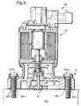
- Fig. 3 is a partially sectioned view of the pressure balancing metering subassembly of Fig. 1 coupled to an actuator subassembly.
-
- Corresponding reference characters indicate corresponding parts throughout the several views. The exemplification set out herein illustrates one preferred embodiment of the invention, in one form, and such exemplification is not to be construed as limiting the scope of the invention in any manner.
- With reference to the Figures, and particularly to Fig. 1, there is shown one embodiment of a modular pressure balancing metering subassembly of the present invention. Pressure balancing metering subassembly (PBMS) 10 includes
piston 12,cylinder 14,elongate shaft 16,elongate poppet 18,seal 24 andbase 26. - Piston 12 is disposed within
cylinder 14. As best shown in Fig. 2,piston 12 includesbottom surface 28 interconnected bycylindrical sidewall 29 totop surface 30.Bottom surface 28 is substantially cylindrical and is disposed around a bottom ofsidewall 29.Top surface 30 is substantially cylindrical and disposed around a top ofsidewall 29.Bottom surface 28 definespiston orifice 32. Piston 12 defines a conicalinner surface 34 which tapers outwardly frombottom surface 28 totop surface 30. Pistonorifice 32 extends axially throughbottom surface 28, terminating at and opening intoinner surface 34. -
Cylinder 14 is a cup-shaped member and includes a radially outward extendingflange 42,top 43 andinner wall 44.Cylinder 14 is received substantially concentrically withinbore 46 ofbase 26 untilflange 42 contacts and seats uponbase 26.Top 43 defines ashaft orifice 48 within which bearingseal 24 is disposed.Bottom surface 28 ofpiston 12 circumferentially engagesinner wall 44 ofcylinder 14 in an air and fluid tight manner.Top surface 30 ofpiston 12 circumferentially engagesinner wall 44 ofcylinder 14 proximate top 43 in an air and fluid tight manner.Pressure chamber 50 is defined betweentop surface 30,inner surface 34 ofpiston 12,inner wall 44 and top 43 ofcylinder 14. -
Elongate shaft 16 includes a first end with a radially-outward extendingshaft flange 60.Elongate shaft 16 extends axially fromshaft flange 60 concentrically through bearingseal 24 and intopressure chamber 50.Bearing seal 24 is configured to sealshaft 16 andshaft orifice 48 in an air and fluid tight manner.Bearing seal 24 maintains this air and fluid tight interface betweenshaft 16 andshaft orifice 48 during reciprocal movement ofshaft 16.Second end 62 ofelongate shaft 16 is reciprocally disposed withinpressure chamber 50 and defines anaxial bore 64 therein.Spring 66 has one end disposed in engagement withflange 60 ofelongate shaft 16, and the other end disposed in engagement with bearingseal 24.Spring 66 exerts an axially-directed force on each offlange 60 and bearingseal 24, thereby maintainingseal 24 in sealing disposition withinshaft orifice 48 and biasingshaft 16 in a direction away frombase 26. -
Elongate poppet 18 includes a plunger-shapedend 70 interconnected with a narrowedstem end 72 at its opposite end, and defines an axially extendingcavity 74 therethrough.Stem end 72 extends throughpiston orifice 32 and is disposed withinpressure chamber 50.Bottom surface 28 ofpiston 12 is tightly seated upon and engagespoppet 18 in an air and fluid tight manner.Stem end 72 is received withinaxial bore 64 of and/or coupled to elongateshaft 16. Thus, reciprocation ofpoppet shaft 16 will, in turn, reciprocatepoppet 18.Stem end 72 defines aradial orifice 78 which intersectscavity 74 thereby fluidly connectingcavity 74 withpressure chamber 50.Axial cavity 74 provides a passageway through which air flows from the areaproximate plunger end 70 ofelongate poppet 18 and intopressure chamber 50. -
Bearing seal 24 is disposed withinshaft orifice 48 ofcylinder 14.Elongate shaft 16 passes through bearingseal 24.Bearing seal 24 surroundselongate shaft 16 in an air and fluid tight manner, thereby sealingpressure chamber 32.Bearing seal 24 maintains this seal during the reciprocal motion ofelongate shaft 16 therein. -
Base 26 defines a metering port 80 (Fig. 3) andmetering chamber 82.Metering port 80 is connected to a source of exhaust gas (not shown).Elongate poppet 18 extends throughmetering port 80.Plunger end 70 ofelongate poppet 18 is disposed proximate to and is configured to sealingly engagemetering port 80. Reciprocal motion ofelongate shaft 16 is transferred to elongatepoppet 18. Such reciprocal motion will bringplunger end 70 ofelongate poppet 18 into and out of sealing engagement withmetering port 80, thereby selectively opening andclosing metering port 80.Plunger end 70 in a default position is disposed in sealing engagement withmetering port 80, thereby preventing any flow of exhaust gas intometering chamber 82.Elongate poppet 18 is selectively reciprocated out of sealing engagement withmetering port 80 to allow exhaust gas to flow therethrough and intometering chamber 82.Base 26 further includes mountingbores 86a and 86b. - Referring now to Fig. 3,
modular EGR valve 100 includes pressure balanced metering subassembly (PBMS) 10 andmodular actuator subassembly 90.Actuator subassembly 90 is coupled toPBMS 10 and selectively reciprocateselongate shaft 16 ofPBMS 10 which, in turn, reciprocates plunger end 70 ofelongate poppet 18 into and out of sealing engagement withmetering port 80. Thus, exhaust gas is selectively allowed to flow throughmetering port 80 and intometering chamber 82. Fasteners, such as, for example, eyelets 95a and 95b are used to couplePBMS 10 toactuator subassembly 90. Fasteners such as, for example,bolts 102a and 102b are used to couple themodular EGR valve 100 toengine 104. - In use, (PBMS) 10 is coupled to
actuator subassembly 90, which is configured to selectively reciprocateelongate shaft 16 and, in turn,elongate poppet 18, thereby sealing and unsealingmetering port 80. Exhaust gas will exert a pressure againstplunger end 70 ofelongate poppet 18. This pressure will include pulsations between a high pressure and a lower pressure. Any pressure and transient pressure surges in the areaproximate plunger 70 will be transferred intopressure chamber 50 throughcavity 74, thereby equalizing the pressure acting onplunger 70 with the pressure inpressure chamber 50. The same pressure acting uponplunger 70 acts uponinner surface 34 ofpiston 12. Therefore, reciprocation ofelongate shaft 16 and, in turn,elongate poppet 18 is accomplished without requiring the force necessary to overcome the back pressure and pressure pulsations present atplunger 70. - The effect of pressure pulsations present at
plunger 70, and/or the pressure differential betweenplunger 70 and stem end 72 ofpoppet 18, are reduced by fluidly connectingpressure chamber 50 with the pressure present inmetering port 80 viacavity 74 ofpoppet 18. By making the surface area of conicalinner surface 34 ofpiston 12 substantially equal to the surface area ofplunger 70, the forces exerted uponpoppet 18 by the pressures present inmetering port 80 andpressure chamber 50 will substantially cancel each other. Thus, reciprocation ofpoppet 18 is rendered substantially immune from pressure differentials and/or pressure fluctuations atmetering port 80 and the force required to reciprocatepoppet 18 is substantially reduced. - In the embodiment shown,
PBMS 10 is coupled toactuator subassembly 90. However, it is to be understood that PBSM 10 can be alternately configured to be coupled or otherwise operably associated with a variously configured actuator subassemblies. - While this invention has been described as having a preferred design, the present invention can be further modified within the spirit and scope of this disclosure. This application is therefore intended to cover any variations, uses, or adaptations of the invention using its general principles. Further, this application is intended to cover such departures from the present disclosure as come within known or customary practice in the art to which this invention pertains and which fall within the limits of the appended claims.
Claims (18)
- A pressure balancing metering subassembly 10 for use with a modular actuator 90 of an EGR valve 100, said pressure balancing metering subassembly 10 comprising:a metering base 26 defining a metering port 80 and a metering chamber 82;an elongate poppet 18 having a first end 70 and a second end 72, said first end 70 normally disposed in sealing engagement with said metering port 80, said poppet 18 being selectively reciprocated to disengage said first end 70 from sealing engagement with said metering port 80 to thereby fluidly connect said metering port 80 with said metering chamber 82; andpressure balancing means balancing a pressure at said first end 70 of said poppet 18 with a pressure at said second end 72 of said poppet 18.
- The pressure balancing metering subassembly 10 of claim 1, wherein said pressure balancing means comprises:a cylinder 14 having a top 43 and a cylindrical sidewall; anda piston 12 disposed within said cylinder 14, said piston 12 sealingly engaging an inner surface 44 of said cylindrical sidewall of said cylinder 14, a pressure chamber 50 being defined between said piston 12, said cylindrical side wall 44 and said top 43 of said cylinder, said second end 72 of said poppet 18 being disposed within said pressure chamber 50, said piston 12 being one of in abutting engagement with and coupled to said poppet 18; andpressure conducting means conducting the pressure at said first end 70 of said poppet 18 to said pressure chamber 50.
- The pressure balancing metering subassembly 10 of claim 2, wherein said pressure conducting means comprises an axial cavity 74 defined by said poppet 18, said axial cavity 74 extending from said first end 70 to said second end 72 to thereby place said pressure chamber 50 into fluid communication with said metering port 80.
- The pressure balancing metering subassembly 10 of claim 3, wherein said metering base 26 defines a bore 46, said bore being substantially concentric with said metering port 80, said cylinder 14 and said bore 46 being in fluid communication.
- The pressure balancing metering subassembly 10 of claim 4, wherein said cylinder 14 includes a flange 42 extending radially outward from said cylindrical sidewall 44, said flange 42 seating upon said a top surface of said metering base 26.
- The pressure balancing metering subassembly 10 of claim 3, wherein said top 43 of said cylinder 14 defines a shaft orifice 48, said metering subassembly 10 further comprising an elongate shaft 16 having a first shaft end 60 and a second shaft end 62, said first shaft end 60 being disposed external to said cylinder 14, said elongate shaft 16 extending through said shaft orifice 48, said second shaft end 62 disposed within said pressure chamber 50 and engaging said second end 72 of said poppet 18.
- The pressure balancing metering subassembly 10 of claim 6, wherein said second shaft end 62 defines an axial shaft bore 64, said second end 72 of said poppet 18 being received partially within said axial shaft bore 64 to thereby couple said shaft 16 to said poppet 18.
- The pressure balancing metering subassembly 10 of claim 6, further comprising a seal 24, said seal engaging said shaft 16 and said shaft orifice 48 in said cylinder 14 to thereby seal together said shaft 16 and said cylinder 14 in an air and fluid tight manner.
- The pressure balancing metering subassembly 10 of claim 3, wherein said piston 12 comprises a substantially cylindrical piston wall 29, a top surface 30 and a bottom surface 28, said top surface 30 and said bottom surface 28 being interconnected by said piston wall 29, a conical inner surface 34 disposed between said bottom surface 28 and said top surface 30, said bottom surface 28 defining an orifice 32 therethrough, said orifice 32 extending from said bottom surface 28 to said conical inner surface 34, said piston 12 sealingly engaging an inner surface 44 of said sidewall of said cylinder 14, said pressure chamber 50 conjunctively defined by said top surface 30 of said piston, said inner surface 34 of said piston, a portion of said inner surface 44 of said sidewall of said cylinder 14, and said top 43 of said cylinder 14, said poppet 18 extending through said orifice 32 to thereby dispose said second end 72 of said poppet 18 within said pressure chamber 50.
- The pressure balancing metering subassembly 10 of claim 9, wherein said conical inner surface 34 of said piston 12 has a first surface area, said first end 70 of said metering poppet 18 having a second surface area, said first surface area being substantially equal to said second surface area.
- A modular EGR valve 100, comprising:
a pressure balancing metering subassembly 10, comprising:a metering base 26 defining a metering port 80 and a metering chamber 82;an elongate poppet 18 having a first end 70 and a second end 72, said first end 70 normally disposed in sealing engagement with said metering port 80, said poppet 18 being selectively reciprocated to disengage said first end 70 from sealing engagement with said metering port 80 to thereby fluidly connect said metering port 80 with said metering chamber 82;pressure balancing means balancing a pressure at said first end 70 of said poppet 18 with a pressure at said second end 72 of said poppet 18; anda modular actuator subassembly 90 configured for being coupled to said pressure balancing metering subassembly 10. - A method of substantially canceling a first force acting upon a valve poppet 18, said first force being the result of a fluid pressure acting upon a first end 70 of the valve poppet 18, said method comprising the steps of:defining a pressure chamber 50;fluidly connecting said pressure chamber 50 to the fluid pressure acting upon said first end 70 of said valve poppet 18 to thereby substantially equalize the fluid pressure with a pressure within the pressure chamber 50;converting the pressure in said pressure chamber to a second force, the second force being substantially equal to and acting upon the valve poppet 18 in a direction substantially opposite to the first force.
- The method of claim 12, wherein said fluidly connecting step comprises defining a fluid passageway 74 within said valve poppet, said fluid passageway extending from said first end 70 to a second end 72 of the poppet 18, said second end 72 of said valve poppet 18 being disposed within said pressure chamber 50.
- The method of claim 12, wherein said defining step comprises a piston 12 being disposed within a cylinder 14 in an air and fluid tight manner to thereby define said pressure chamber 50 between an inner surface 34 of said piston 12 and an inner surface 44 of said cylinder 14.
- The method of claim 14, wherein said converting step comprises said piston 12 engaging said second end 72 of said valve poppet 18.
- The method of claim 15, wherein said piston 12 is coupled to said second end 72 of said valve poppet 18.
- The method of claim 12, wherein said converting step comprises providing said piston 12 with an inner surface 34, said inner surface having a surface area being substantially equal to a surface area of said first end 70 of said valve poppet 18.
- An internal combustion engine 104 having a pressure balancing metering subassembly 10, said pressure balancing metering subassembly comprising:a metering base 26 defining a metering port 80 and a metering chamber 82, said metering base 26 being coupled to said engine 104;an elongate poppet 18 having a first end 70 and a second end 72, said first end 70 normally disposed in sealing engagement with said metering port 80, said poppet 18 being selectively reciprocated to disengage said first end 70 from sealing engagement with said metering port 80 to thereby fluidly connect said metering port 80 with said metering chamber 82; andpressure balancing means balancing a pressure at said first end 70 of said poppet 18 with a pressure at said second end 72 of said poppet 18.
Applications Claiming Priority (2)
| Application Number | Priority Date | Filing Date | Title |
|---|---|---|---|
| US18453000P | 2000-02-24 | 2000-02-24 | |
| US184530P | 2000-02-24 |
Publications (2)
| Publication Number | Publication Date |
|---|---|
| EP1128054A2 true EP1128054A2 (en) | 2001-08-29 |
| EP1128054A3 EP1128054A3 (en) | 2002-08-28 |
Family
ID=22677284
Family Applications (1)
| Application Number | Title | Priority Date | Filing Date |
|---|---|---|---|
| EP01200543A Withdrawn EP1128054A3 (en) | 2000-02-24 | 2001-02-16 | Pressure balancing metering subassembly for use with a modular egr valve |
Country Status (2)
| Country | Link |
|---|---|
| US (1) | US6435168B1 (en) |
| EP (1) | EP1128054A3 (en) |
Cited By (1)
| Publication number | Priority date | Publication date | Assignee | Title |
|---|---|---|---|---|
| WO2015055568A1 (en) * | 2013-10-14 | 2015-04-23 | Continental Automotive Gmbh | Valve |
Families Citing this family (8)
| Publication number | Priority date | Publication date | Assignee | Title |
|---|---|---|---|---|
| US6871699B1 (en) | 1999-08-16 | 2005-03-29 | Delphi Technologies, Inc. | Engine coolant conduit with integral alternator and exhaust gas recirculation valve |
| US6759934B2 (en) * | 2000-09-11 | 2004-07-06 | Delphi Technologies, Inc. | Proportionally-controllable solenoid actuator |
| GB0123773D0 (en) | 2001-10-03 | 2001-11-21 | Delphi Tech Inc | Metering valve arrangement |
| US6715475B2 (en) | 2001-10-26 | 2004-04-06 | Siemens Vdo Automotive, Incorporated | Exhaust gas recirculation valve |
| US6866063B2 (en) | 2002-09-06 | 2005-03-15 | Delphi Technologies, Inc. | Low leak pressure control actuator |
| US6871668B2 (en) * | 2003-01-13 | 2005-03-29 | Delphi Technologies Inc. | Variable force actuator with a double needle poppet assembly |
| CA2514922C (en) * | 2003-01-31 | 2012-01-10 | Lim Technology, Llc | Pneumatically actuated valve for internal combustion engines |
| CN109139308A (en) * | 2015-03-19 | 2019-01-04 | 常州科普动力机械有限公司 | The working method of internal combustion engine EGR check valve |
Family Cites Families (8)
| Publication number | Priority date | Publication date | Assignee | Title |
|---|---|---|---|---|
| US5255659A (en) * | 1992-09-28 | 1993-10-26 | Ford Motor Company | Pressure balanced exhaust gas recirculation valve |
| DE69729863T2 (en) * | 1996-05-20 | 2005-08-25 | Borgwarner Inc., Auburn Hills | AUTOMATIC FLUID CONTROL SYSTEM WITH PRESSURE BALANCED ELECTROMAGNET VALVE |
| DE19721993A1 (en) * | 1997-05-26 | 1998-12-17 | Ammermann Klaus Dr | Exhaust gas recirculation valve with pressure compensation |
| DE19824103A1 (en) * | 1998-05-29 | 1999-12-02 | Pierburg Ag | Exhaust control valve for feedback of exhaust into combustion air induction channel of IC engine |
| US6557346B1 (en) * | 1999-02-02 | 2003-05-06 | A. Kayser Automotive Systems Gmbh | Gas conducting device |
| US6217001B1 (en) * | 1999-06-29 | 2001-04-17 | Delphi Technologies, Inc. | Pressure balanced gas valve |
| DE19935483A1 (en) * | 1999-07-28 | 2001-02-01 | Delphi Tech Inc | Control valve for exhaust gas recirculation |
| DE19936657A1 (en) * | 1999-08-04 | 2001-02-15 | Mannesmann Vdo Ag | Control valve |
-
2000
- 2000-11-22 US US09/721,225 patent/US6435168B1/en not_active Expired - Fee Related
-
2001
- 2001-02-16 EP EP01200543A patent/EP1128054A3/en not_active Withdrawn
Cited By (1)
| Publication number | Priority date | Publication date | Assignee | Title |
|---|---|---|---|---|
| WO2015055568A1 (en) * | 2013-10-14 | 2015-04-23 | Continental Automotive Gmbh | Valve |
Also Published As
| Publication number | Publication date |
|---|---|
| US6435168B1 (en) | 2002-08-20 |
| EP1128054A3 (en) | 2002-08-28 |
Similar Documents
| Publication | Publication Date | Title |
|---|---|---|
| US6247461B1 (en) | High flow gas force balanced EGR valve | |
| US8955501B2 (en) | PCV valve mounting structures | |
| US6182646B1 (en) | Electromechanically actuated solenoid exhaust gas recirculation valve | |
| US6217001B1 (en) | Pressure balanced gas valve | |
| EP2182185B1 (en) | Crankcase ventilation system for engine | |
| US20040211400A1 (en) | Recycling circuit for crankcase gases of an internal combustion engine | |
| US8424499B2 (en) | Pneumatic system for controlling the valves of an internal combustion engine | |
| US6435168B1 (en) | Pressure balancing metering subassembly for use with a modular EGR valve | |
| KR20100091878A (en) | Control valve | |
| EP0900931A2 (en) | Exhaust gas recirculation valve | |
| JP2004522036A (en) | Valve device for pressure control in a combustion engine and method for such pressure control | |
| CN105121831A (en) | Piston pump, in particular high-pressure fuel pump | |
| AU2005200885B2 (en) | Pressure reducing valve | |
| US6497225B1 (en) | EGR metering subassembly including a gas arrestor | |
| US6604727B1 (en) | Control valve | |
| US20030042450A1 (en) | Force-balanced gas control valve | |
| EP0900934B1 (en) | Fuel supply apparatus | |
| EP1398494B1 (en) | Exhaust gas recirculation valve having low drag | |
| JPS6116219A (en) | Blow-by gas flow rate control valve for internal-combustion engine | |
| US6725661B1 (en) | Valve device | |
| JP3620888B2 (en) | Actuator capable of multi-stage positioning | |
| CN114810373B (en) | Integrated auxiliary air system for heavy-duty engines | |
| JP4594254B2 (en) | PCV valve | |
| JPH10103166A (en) | Exhaust gas recirculation valve | |
| JPS6116220A (en) | Oil consumption reducing device for internal-combustion engine |
Legal Events
| Date | Code | Title | Description |
|---|---|---|---|
| PUAI | Public reference made under article 153(3) epc to a published international application that has entered the european phase |
Free format text: ORIGINAL CODE: 0009012 |
|
| AK | Designated contracting states |
Kind code of ref document: A2 Designated state(s): AT BE CH CY DE DK ES FI FR GB GR IE IT LI LU MC NL PT SE TR |
|
| AX | Request for extension of the european patent |
Free format text: AL;LT;LV;MK;RO;SI |
|
| PUAL | Search report despatched |
Free format text: ORIGINAL CODE: 0009013 |
|
| AK | Designated contracting states |
Kind code of ref document: A3 Designated state(s): AT BE CH CY DE DK ES FI FR GB GR IE IT LI LU MC NL PT SE TR |
|
| AX | Request for extension of the european patent |
Free format text: AL;LT;LV;MK;RO;SI |
|
| 17P | Request for examination filed |
Effective date: 20030228 |
|
| AKX | Designation fees paid |
Designated state(s): DE FR GB |
|
| STAA | Information on the status of an ep patent application or granted ep patent |
Free format text: STATUS: THE APPLICATION IS DEEMED TO BE WITHDRAWN |
|
| 18D | Application deemed to be withdrawn |
Effective date: 20040901 |