EP1127978A2 - Vacuum belt conveyor - Google Patents
Vacuum belt conveyor Download PDFInfo
- Publication number
- EP1127978A2 EP1127978A2 EP01103851A EP01103851A EP1127978A2 EP 1127978 A2 EP1127978 A2 EP 1127978A2 EP 01103851 A EP01103851 A EP 01103851A EP 01103851 A EP01103851 A EP 01103851A EP 1127978 A2 EP1127978 A2 EP 1127978A2
- Authority
- EP
- European Patent Office
- Prior art keywords
- vacuum
- belt
- belt conveyor
- conveyor
- blower
- Prior art date
- Legal status (The legal status is an assumption and is not a legal conclusion. Google has not performed a legal analysis and makes no representation as to the accuracy of the status listed.)
- Granted
Links
Images


Classifications
-
- D—TEXTILES; PAPER
- D21—PAPER-MAKING; PRODUCTION OF CELLULOSE
- D21G—CALENDERS; ACCESSORIES FOR PAPER-MAKING MACHINES
- D21G9/00—Other accessories for paper-making machines
- D21G9/0063—Devices for threading a web tail through a paper-making machine
-
- B—PERFORMING OPERATIONS; TRANSPORTING
- B65—CONVEYING; PACKING; STORING; HANDLING THIN OR FILAMENTARY MATERIAL
- B65H—HANDLING THIN OR FILAMENTARY MATERIAL, e.g. SHEETS, WEBS, CABLES
- B65H20/00—Advancing webs
- B65H20/10—Advancing webs by a feed band against which web is held by fluid pressure, e.g. suction or air blast
Definitions
- a vacuum belt conveyor having a vacuum box within the loop of the conveyor belt.
- the conveying run of the belt is travelling directly across the open surface (e.g. across a cover plate comprising suction openings) of the vacuum box, so that the negative pressure propagates through the conveying run of the belt in order to draw a web or a tail to be guided by the conveyor belt by suction.
- a side wall of the vacuum box is connected via a vacuum pipe to a vacuum source which is usually positioned at a certain distance from the vacuum belt conveyor.
- said vacuum pipe (which must be rather voluminous) must be designed as a flexible hose. This flexible hose is generally a disturbing factor.
- the resulting vacuum pulsation can cause problems in the threading operation, especially if the conveyor is inverted. In this case the web or tail may fall off the conveyor, especially if an over-pressure is produced to detach the web or tail from the downstream end of the conveying run of the belt as disclosed in Figs. 5A and 5B of US '215.
- a novel position of a vacuum blower namely within the loop of the air-pervious endless belt.
- the vacuum blower is positioned within the loop of the belt in such a way that the inflow of the blower is arranged in close proximity to the inside of the conveying run of the belt.
- the at least one vacuum blower is arranged in the place of the formerly provided vacuum box.
- the vacuum belt conveyor comprises a vacuum box
- the at least one vacuum blower is positioned inside the vacuum box near the return run of the belt, with the inflow of the blower being open towards the open surface (e.g. to a cover plate comprising suction openings) of the vacuum box.
- the open surface e.g. to a cover plate comprising suction openings
- the vacuum blower is driven by an airturbine.
- the benefit of such an airturbine is that it has a very small overall height (measured along the rotational axis). This is an important advantage for the positioning of the vacuum blower within the loop of the belt.
- the vacuum blower (being positioned inside the belt loop) may be driven by an electric motor, which again should have a very small overall height.
- the vacuum belt conveyor is supported by a rotatable or pivotable support, so that the complete vacuum belt conveyor including the vacuum blower can be moved, e. g. from a functional position to a non-functional position and back to the functional position.
- the objects mentioned above are attained by creating the negative pressure (required in the belt loop) by means of an air stream induced by a propulsion jet, with the air stream and the propulsion jet being joined to a "combined flow" which is positively directed to the outside of the belt conveyor (claims 16 - 24).
- each blow box 66, 67 has a wall 68 being positioned in close proximity to the cover pate 16 and being divergent therefrom.
- a second wall 69 of each blow box comprises a rounded edge which forms together with the free end of the first mentioned wall 68 a nozzle orifice 70.
- Each blow box 66, 67 is connected to a source 71 of pressurized air so that the nozzle orifice 70 produces a propulsion jet which, due to the Coanda-effect, adheres to said second wall 69.
- the propulsion jet induces a secondary air stream passing through the air-pervious belt 20 and through the openings of cover pate 16, thereby creating a negative pressure at the belt 20 and causing the web or tail 25 to cling to the belt.
- a guide plate 72 may be provided to direct said combined flow sideways out of the belt loop.
- the combined flow may go through the return run of belt 20.
- the propulsion jets are flowing towards the middle of the conveyor when passing the nozzle orifices 70.
- at least two blow boxes of the type shown in Fig. 3 may also be arranged in such a way that the two or more propulsion jets are flowing in a direction from the middle of the conveyor towards the outside.
- blow box 75 is provided below the cover plate 23.
- the wall of the blow box which is positioned in close proximity to the cover plate 23 has a plurality of outlets 76, in order to produce propulsion jets. These again induce secondary air streams in order to create the negative pressure required at the belt 20.
- the vacuum belt conveyor shown in Fig. 8 differs from that of Fig. 1 in that inside the loop of belt 20 a vacuum box 21 is provided having a cover plate 23 which has openings (e.g. slots) and which contacts the conveying run of belt 20.
- the pulleys 22 (supported by vacuum box 21) have a relatively small diameter (compared with Fig. 1). Therefore, also the height of the vacuum box 21 is relatively small. Nevertheless, at least one air turbine driven vacuum blower 24 is positioned inside the vacuum box 21. This is possible due to a very compact blower design described below with the aid of Figs. 9 - 11. There is a certain distance d between the inner surface of cover plate 23 and the suction inlet of the blower(s) 24.
- one of the pulleys 22 is driven by a motor M' which is located in the interior of this pulley. Therefore, in summary, one of the remarkable features of the vacuum belt conveyor shown in Fig. 8 is its very compact design because both, the vacuum source 24 and the drive motor M' are located in the interior of the apparatus.
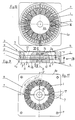
- the airturbine driven vacuum blower 24 shown in Figs. 9 - 11 has an extremely small overall length B (measured along the rotational axis 11).
- the overall length B is less than one third of the outer diameter D of the impeller 10.
- the impeller 10 comprises a rim of blower vanes 1, which produce an air stream A; the impeller also comprises a rim of turbine vanes 2 which is used to drive the impeller 10.
- said channel 8 is open towards the rim of turbine vanes 2, but only towards a sector of that rim (according to Fig. 11 about 25 % of the total rim 2).
- the pressurized fluid F flows through the rim of turbine vanes 2 in a substantially axial direction, thereby producing the required rotation of the impeller 10.
- the rotating impeller draws in air through the air inlet channels 17. In this way, an air stream A is produced which is exhausted through the outlet channels 16 in a substantially axial direction, and a negative pressure is produced in front of the inlet channels 17.
Landscapes
- Physics & Mathematics (AREA)
- Fluid Mechanics (AREA)
- Delivering By Means Of Belts And Rollers (AREA)
- Structure Of Belt Conveyors (AREA)
- Paper (AREA)
- Advancing Webs (AREA)
- Belt Conveyors (AREA)
Abstract
Description
It is a further object of the invention at least to minimize the length of a pipe connection from a vacuum belt conveyor to its vacuum source or to avoid the pipe connection completely.
A further object of the present invention is to provide an improved vacuum belt conveyor wherein the level of the negative pressure is as stable (or continuous) as possible along the travel path of the conveying run of the belt, in order to obtain an optimized threading operation.
If needed, the vacuum blower (being positioned inside the belt loop) may be driven by an electric motor, which again should have a very small overall height. Preferably, the vacuum belt conveyor is supported by a rotatable or pivotable support, so that the complete vacuum belt conveyor including the vacuum blower can be moved, e. g. from a functional position to a non-functional position and back to the functional position.
The necessity of providing an external voluminous vacuum pipe is eliminated, because the vacuum source (vacuum blower or propulsion jet device) is positioned inside of the conveyor, namely inside of the belt loop. However, at the same time, the discharge of the air emitted by the vacuum blower (and by the airturbine if existing) or by a propulsion jet device can be reliably controlled, so that the emitted air does not disturb the travel of the paper web or threading tail. Also, the airflow produced by the blower and/or the airturbine or produced by the propulsion jet keeps the vacuum belt conveyor much cleaner than with previous known conveyor designs, in particular if the discharge air is directed through the return run of the belt.
- Fig. 1
- shows a first embodiment of the invention with airturbine driven vacuum blowers arranged within the loop of the belt;
- Fig. 2
- shows another type of vacuum belt conveyor creating the negative pressure by means of a propulsion jet;
- Fig. 3
- shows a cross-section along line III - III of Fig. 2;
- Fig. 4
- shows a modification of Fig. 3;
- Fig. 5
- shows a vacuum belt conveyor with so-called air amplifiers;
- Fig. 6
- is a view from above onto the air amplifiers of Fig. 5;
- Fig. 7
- is an enlarged section through an air amplifier;
- Fig. 8
- is a longitudinal section of a further vacuum belt conveyor comprising a more compact vacuum blower positioned in a vacuum box;
- Fig. 9
- is a section through the compact vacuum blower of Fig. 8;
- Fig. 10
- is a view along arrow X of Fig. 9;
- Fig. 11
- is a view along arrow XI of Fig. 9.
Claims (24)
- Vacuum belt conveyor, which is suitable for guiding a running web (25), e.g. paper web, in particular a threading tail of the web, said belt conveyor having the following features:a) An air-pervious endless conveyor belt (20) is travelling around at least two pulleys (22) and forming a loop comprising a conveying run as well as a return run,b) means to establish a negative pressure within said loop at the inside of said conveying run of the belt (20),c) characterized in that said means comprise at least one vacuum blower (28; 24) which is positioned within the loop of the belt (20).
- Vacuum belt conveyor as claimed in claim 1, wherein the at least one vacuum blower has an inflow, characterized in that the inflow of the blower is arranged in close proximity to the inside of the conveying run of the belt (20) (Fig. 1).
- Vacuum belt conveyor as claimed in claim 1, wherein a vacuum box (21) is positioned within the loop of the belt (20), which vacuum box is open towards the inside of the conveying run of the belt, characterized in that the at least one vacuum blower (24) is arranged inside said vacuum box (21) (Fig. 8).
- Vacuum belt conveyor as claimed in claim 3, characterized in that the vacuum blower (24) is positioned near the return run of the belt (20), with a distance (d) being provided between the blower's inflow and a coverplate (23) of the vacuum box (21).
- Vacuum belt conveyor as claimed in claim 1, characterized in that the vacuum box (21) has at least one exhaust opening (19) open towards the return run of the belt (20).
- Vacuum belt conveyor as claimed in claim 1, characterized in that the impeller (10) of the vacuum blower (24) is connected to a driving airturbine (2).
- Vacuum belt conveyor as claimed in claim 6, characterized in that the impeller (10) of the vacuum blower (24) and the airturbine (2) comprise a common housing (3, 4) (Figs. 9 - 11).
- Vacuum belt conveyor as claimed in claim 6 or 7, characterized in the following features:a) the impeller (10) comprises a rim of blower vanes (1) producing an air stream
(A) and a rim of turbine vanes (2) driving the impeller by means of a pressurized fluid (F);b) the one rim of vanes is wrapped around the other rim of vanes. - Vacuum belt conveyor as claimed in claim 8, characterized in that the rim of turbine vanes (2) is wrapped around the rim of blower vanes (1).
- Vacuum belt conveyor as claimed in claim 8, characterized in that blower vanes (1) extend radially.
- Vacuum belt conveyor as claimed in claim 8, characterized in that the turbine vanes (2) extend radially.
- Vacuum belt conveyor as claimed in claim 8, characterized in that the housing (3, 4) comprises an inlet channel (8) for the pressurized fluid (F) which is open towards only a sector of the rim of turbine vanes (2).
- Vacuum belt conveyor as claimed in claim 7, characterized in that the housing comprises an inlet portion (3) and an outlet portion (4), with each portion being formed substantially as a disc and supporting a bearing (5) of the impeller (10).
- Vacuum belt conveyor as claimed in claim 6, characterized in that the overall length (B) measured along the impeller's axis (11) is only a fraction (e.g. 1/3) of the impeller's (10) outer diameter (D).
- Vacuum belt conveyor as claimed in claim 8, characterized in that the air stream
(A) and the driving pressurized fluid (F) are exhausted substantially parallel to the impellers axis (11) and through the return run of the belt (20). - Vacuum belt conveyor, which is suitable for guiding a running web (25), e.g. paper web, in particular a threading tail of the web, said belt conveyor comprising an air-pervious endless conveyor belt (20) which is travelling around at least two pulleys (22) and which is forming a loop comprising a conveying run as well as a return run; further comprising means to establish a negative pressure within said loop at the inside of said conveying run of the belt (20), characterized in the following features:a) said means comprise an element (66, 67 or 75 or 80) positioned within the belt loop, which element produces at least one propulsion jet (of air and/or liquid);b) the arrangement being such that the propulsion jet induces an air stream creating said negative pressure;c) further means are provided to direct a combined flow of the propulsion jet and the air stream to the outside of the belt conveyor.
- Vacuum belt conveyor as claimed in claim 16, characterized in that within the belt loop, at least one blow box (66, 67 or 75) is arranged which is connected to a source (71) of pressurized air and/or liquid and which has at least one nozzle orifice (70 or 76) producing said at least one propulsion jet.
- Vacuum belt conveyor as claimed in claim 17, characterized in that said at least one blow box (66, 67 or 75) extends in the direction of belt travel and that the propulsion jet is flowing across the belt travel direction.
- Vacuum belt conveyor as claimed in claim 18, characterized in that two blow boxes (66, 67) are provided which are arranged side by side (as seen in a cross-section of the conveyor).
- Vacuum belt conveyor as claimed in claim 19, characterized in that the propulsion jets are flowing towards the middle of the conveyor (against each other) when passing the nozzle orifices (70) and in that each blow box (66, 67) has a rounded edge to deviate the propulsion jet in a direction towards the return run of the belt (20).
- Vacuum belt conveyor as claimed in claim 20, characterized in that a guide element (72) is provided to direct the combined flow of propulsion jet and air sideways out of the belt loop.
- Vacuum belt conveyor as claimed in claim 20, characterized in that the propulsion jets are flowing from the middle of the conveyor to the outside.
- Vacuum belt conveyor as claimed in claim 16, characterized in that at least one so-called air amplifier (80) is used to create the required negative pressure within the belt loop.
- Vacuum belt conveyor as claimed in claim 16, characterized in that an air-pervious plate (23) is provided which contacts the inner side of the conveying run of the belt (20).
Priority Applications (1)
| Application Number | Priority Date | Filing Date | Title |
|---|---|---|---|
| EP05019042A EP1605098A1 (en) | 2000-02-26 | 2001-02-16 | Vacuum belt conveyor |
Applications Claiming Priority (4)
| Application Number | Priority Date | Filing Date | Title |
|---|---|---|---|
| DE10009188 | 2000-02-26 | ||
| DE2000109188 DE10009188A1 (en) | 2000-02-26 | 2000-02-26 | Vacuum belt conveyor for paper web threading in production line, has vacuum blower positioned within the air-pervious endless belt loop to generate low pressure at inner side of conveying path |
| DE20012843U | 2000-07-25 | ||
| DE20012843U DE20012843U1 (en) | 2000-07-25 | 2000-07-25 | Blower with integrated blower drive |
Related Child Applications (1)
| Application Number | Title | Priority Date | Filing Date |
|---|---|---|---|
| EP05019042A Division EP1605098A1 (en) | 2000-02-26 | 2001-02-16 | Vacuum belt conveyor |
Publications (3)
| Publication Number | Publication Date |
|---|---|
| EP1127978A2 true EP1127978A2 (en) | 2001-08-29 |
| EP1127978A3 EP1127978A3 (en) | 2002-01-30 |
| EP1127978B1 EP1127978B1 (en) | 2006-01-04 |
Family
ID=26004538
Family Applications (2)
| Application Number | Title | Priority Date | Filing Date |
|---|---|---|---|
| EP01103851A Expired - Lifetime EP1127978B1 (en) | 2000-02-26 | 2001-02-16 | Vacuum belt conveyor |
| EP05019042A Withdrawn EP1605098A1 (en) | 2000-02-26 | 2001-02-16 | Vacuum belt conveyor |
Family Applications After (1)
| Application Number | Title | Priority Date | Filing Date |
|---|---|---|---|
| EP05019042A Withdrawn EP1605098A1 (en) | 2000-02-26 | 2001-02-16 | Vacuum belt conveyor |
Country Status (5)
| Country | Link |
|---|---|
| US (1) | US6630057B2 (en) |
| EP (2) | EP1127978B1 (en) |
| AT (1) | ATE315125T1 (en) |
| CA (1) | CA2337749A1 (en) |
| DE (1) | DE60116404T2 (en) |
Cited By (4)
| Publication number | Priority date | Publication date | Assignee | Title |
|---|---|---|---|---|
| WO2008141890A1 (en) * | 2007-05-18 | 2008-11-27 | Voith Patent Gmbh | Device for guiding a material web strip |
| US7500553B2 (en) | 2004-03-11 | 2009-03-10 | Metso Paper, Inc. | Belt conveyor for transferring a web threading tail in a web manufacturing machine and a method for changing the belt loop of a belt conveyor for a web threading tail in a web manufacturing machine |
| EP1792860A3 (en) * | 2005-11-30 | 2009-03-11 | Andritz Küsters GmbH | Vacuum web transport device for guiding a running web |
| US7510069B2 (en) | 2004-03-11 | 2009-03-31 | Metso Paper, Inc. | Vacuum belt conveyor for transferring a web threading tail in a web manufacturing machine |
Families Citing this family (16)
| Publication number | Priority date | Publication date | Assignee | Title |
|---|---|---|---|---|
| DE20019346U1 (en) * | 2000-11-14 | 2001-02-22 | Voith Paper Patent GmbH, 89522 Heidenheim | Vacuum belt conveyor |
| FI116910B (en) * | 2002-11-04 | 2006-03-31 | Metso Paper Inc | Procedure and apparatus for a paper machine's on-line finishing |
| DE10305414B3 (en) * | 2003-02-06 | 2004-09-16 | Sms Demag Ag | Device for transferring or threading tape starts |
| FI118182B (en) | 2005-10-25 | 2007-08-15 | Metso Paper Inc | Negative belt conveyor for a sheet forming machine for conveying feed tip |
| US9029731B2 (en) | 2007-01-26 | 2015-05-12 | Electro Scientific Industries, Inc. | Methods and systems for laser processing continuously moving sheet material |
| NO327504B1 (en) | 2007-10-26 | 2009-07-27 | Ntnu Technology Transfer As | An ejector for fluids |
| US8398063B2 (en) * | 2008-12-10 | 2013-03-19 | Gross International Americas, Inc. | Ribbon transport apparatus and method |
| DE102009001743A1 (en) | 2009-03-23 | 2010-09-30 | Voith Patent Gmbh | Device for guiding a material web strip |
| US8388246B2 (en) * | 2009-09-15 | 2013-03-05 | Xerox Corporation | Web driven vacuum transport |
| CN105752686B (en) * | 2012-04-03 | 2018-09-21 | 株式会社尼康 | Substrate board treatment |
| DE102016104926A1 (en) | 2016-03-16 | 2017-09-21 | MAi GmbH & Co. KG | Process for the production of a multi-layered backing of fiber-reinforced mats with a thermoplastic or thermosetting matrix at least partially surrounding the fibers, and also a production plant for carrying out the process |
| US11071254B2 (en) * | 2016-07-19 | 2021-07-27 | Deere & Company | System and method for directing a module wrap |
| CN107323781B (en) * | 2017-08-04 | 2023-07-25 | 杨洋 | Label conveying method and device for labeling small-diameter long cylindrical workpiece |
| AU2020288201A1 (en) * | 2019-06-07 | 2022-02-03 | Beacon Lighting International Limited | Airflow device |
| CN112357456A (en) * | 2020-11-03 | 2021-02-12 | 周启燕 | Conveyor conveyor with vacuum anti-separation structure |
| CN114438349B (en) * | 2022-02-07 | 2022-12-13 | 江苏南方永磁科技有限公司 | A tombarthite feed liquid income groove conveyor for tombarthite separation extraction |
Family Cites Families (19)
| Publication number | Priority date | Publication date | Assignee | Title |
|---|---|---|---|---|
| US3425610A (en) * | 1966-06-29 | 1969-02-04 | Koppers Co Inc | Vacuum device for advancing a continuous web |
| US3140030A (en) | 1962-04-26 | 1964-07-07 | Koppers Co Inc | Vacuum device for pulling a continuous web |
| US3355349A (en) * | 1964-12-14 | 1967-11-28 | Andrew G Devlin | Apparatus for conveying lead strip from driers to calenders in paper-making |
| US3741116A (en) * | 1970-06-25 | 1973-06-26 | American Screen Process Equip | Vacuum belt |
| US3756912A (en) * | 1970-12-31 | 1973-09-04 | Durand Machine Co Ltd | Conveyor mechanism for transferring paper web |
| US3679112A (en) * | 1971-02-26 | 1972-07-25 | Black James | Vacuum belt guiding means |
| US4022366A (en) * | 1976-03-22 | 1977-05-10 | Durad Machine Company Ltd. | Sheet handling apparatus |
| US4294540A (en) * | 1980-01-10 | 1981-10-13 | Xerox Corporation | Document belt vacuum manifold |
| JPS57182423A (en) * | 1981-05-08 | 1982-11-10 | Mitsubishi Heavy Ind Ltd | Pasting device |
| FI69145C (en) * | 1984-07-05 | 1985-12-10 | Valmet Oy | ANORDINATION AND ENCLOSURE OF TRANSPORT AND STATIONING OF BANANS SPETSDRAGNINGSBAND |
| US4660752A (en) * | 1985-08-29 | 1987-04-28 | Compak/Webcor Manufacturing Packaging Co. | Vacuum feeder for continuous web |
| US4698919A (en) * | 1986-04-08 | 1987-10-13 | Beloit Corp. | Apparatus for assisting the transfer of a web to a drying section |
| DE9013654U1 (en) | 1990-09-28 | 1991-01-10 | Schön & Cie AG, 6780 Pirmasens | Punching machine |
| DE19506194A1 (en) | 1995-02-23 | 1996-08-29 | Melzer Maschinenbau Gmbh | Device for conveying a web through stations of a plant |
| DE19601989C2 (en) * | 1996-01-20 | 2002-01-31 | Voith Paper Patent Gmbh | Arrangement for guiding a material web |
| CA2190563C (en) * | 1996-11-18 | 1999-10-26 | Ralph Mancini | Device and method to stabilize sheet between press section and dryer section of a paper-making machine |
| DE19647919A1 (en) | 1996-11-20 | 1998-05-28 | Voith Sulzer Papiermasch Gmbh | Moving paper or cardboard web guide |
| FI112267B (en) * | 1998-09-29 | 2003-11-14 | Metso Paper Inc | Apparatus for guiding and controlling the web's tip-pulling tape in a paper machine |
| DE20001082U1 (en) * | 2000-01-22 | 2000-04-13 | Langbein & Engelbracht GmbH, 44879 Bochum | Arrangement for guiding a flexible material web |
-
2001
- 2001-02-16 AT AT01103851T patent/ATE315125T1/en not_active IP Right Cessation
- 2001-02-16 DE DE60116404T patent/DE60116404T2/en not_active Expired - Lifetime
- 2001-02-16 EP EP01103851A patent/EP1127978B1/en not_active Expired - Lifetime
- 2001-02-16 EP EP05019042A patent/EP1605098A1/en not_active Withdrawn
- 2001-02-22 CA CA002337749A patent/CA2337749A1/en not_active Abandoned
- 2001-02-23 US US09/792,597 patent/US6630057B2/en not_active Expired - Fee Related
Cited By (5)
| Publication number | Priority date | Publication date | Assignee | Title |
|---|---|---|---|---|
| US7500553B2 (en) | 2004-03-11 | 2009-03-10 | Metso Paper, Inc. | Belt conveyor for transferring a web threading tail in a web manufacturing machine and a method for changing the belt loop of a belt conveyor for a web threading tail in a web manufacturing machine |
| US7510069B2 (en) | 2004-03-11 | 2009-03-31 | Metso Paper, Inc. | Vacuum belt conveyor for transferring a web threading tail in a web manufacturing machine |
| EP1792860A3 (en) * | 2005-11-30 | 2009-03-11 | Andritz Küsters GmbH | Vacuum web transport device for guiding a running web |
| US7625465B2 (en) | 2005-11-30 | 2009-12-01 | Andritz Kusters Gmbh | Vacuum belt conveying device for guiding a moving web |
| WO2008141890A1 (en) * | 2007-05-18 | 2008-11-27 | Voith Patent Gmbh | Device for guiding a material web strip |
Also Published As
| Publication number | Publication date |
|---|---|
| US6630057B2 (en) | 2003-10-07 |
| DE60116404D1 (en) | 2006-03-30 |
| ATE315125T1 (en) | 2006-02-15 |
| EP1127978A3 (en) | 2002-01-30 |
| EP1127978B1 (en) | 2006-01-04 |
| CA2337749A1 (en) | 2001-08-26 |
| US20010050154A1 (en) | 2001-12-13 |
| DE60116404T2 (en) | 2006-08-03 |
| EP1605098A1 (en) | 2005-12-14 |
Similar Documents
| Publication | Publication Date | Title |
|---|---|---|
| EP1605098A1 (en) | Vacuum belt conveyor | |
| US6821391B2 (en) | Former and process for producing a tissue web | |
| FI71371C (en) | FOERFARANDE FOER AOSTADKOMMA UNDERTRYCK I EN SECTOR AV EN VALSSAMT EN SUGVALS | |
| FI124385B (en) | Arrangement for cutting and removing a border strip | |
| US6425512B2 (en) | Web handling process | |
| FI66948B (en) | SYSTEM FOER TORRFORMNING AV PAPPER ELLER ANNAT ARMMATERIAL AV PARTIKLAR ELLER FIBER | |
| JPH01156263A (en) | Air guidance box for stabilizing travelling of web, particularly, paper web | |
| JPS5912583B2 (en) | Pneumatic transport method for web material and web material transport device | |
| JPH01239186A (en) | Apparatus for drying strip material | |
| KR880001890A (en) | Device to assist web transport | |
| US6290817B1 (en) | Device for conveying and guiding a lead-in strip of a web in a paper machine | |
| US5860223A (en) | Device for drying a web | |
| CA2095461C (en) | Method and apparatus for eliminating the flutter of a paper web in the dryer section of a papermaking machine between two single felt configurations therein | |
| US5230168A (en) | Vacuum generation in the pocket of a single wire dryer group | |
| JPH08256750A (en) | Device for deriving excess working air from the distributor of a tobacco processing machine | |
| FI65461C (en) | FOER FAR INSPECTION AND PAPER MACHINERY FOR STABILIZATION OF PAPER MACHINES | |
| EP1276921B1 (en) | Method and device for conveying planar ribbon of crimped fiber using air jets | |
| MXPA03003888A (en) | Arrangement within a yankee cylinder or the like and a roller of a paper machine. | |
| US20050230447A1 (en) | Vacuum belt conveyor for transferring a web threading tail in a web manufacturing machine | |
| FI82902C (en) | KRAEPPSCHABER. | |
| FI115233B (en) | Apparatus for conveying conveyor belts in paper machine | |
| KR840002122B1 (en) | Foundation | |
| JPH02221421A (en) | Method and apparatus for dust-removing of sliver after carding | |
| CA2687551C (en) | Apparatus for guiding a material web strip | |
| CN100436670C (en) | Spinning machine with twisting device |
Legal Events
| Date | Code | Title | Description |
|---|---|---|---|
| PUAI | Public reference made under article 153(3) epc to a published international application that has entered the european phase |
Free format text: ORIGINAL CODE: 0009012 |
|
| AK | Designated contracting states |
Kind code of ref document: A2 Designated state(s): AT BE CH CY DE DK ES FI FR GB GR IE IT LI LU MC NL PT SE TR Kind code of ref document: A2 Designated state(s): AT DE FI SE |
|
| AX | Request for extension of the european patent |
Free format text: AL;LT;LV;MK;RO;SI |
|
| PUAL | Search report despatched |
Free format text: ORIGINAL CODE: 0009013 |
|
| AK | Designated contracting states |
Kind code of ref document: A3 Designated state(s): AT BE CH CY DE DK ES FI FR GB GR IE IT LI LU MC NL PT SE TR |
|
| AX | Request for extension of the european patent |
Free format text: AL;LT;LV;MK;RO;SI |
|
| 17P | Request for examination filed |
Effective date: 20020730 |
|
| AKX | Designation fees paid |
Free format text: AT DE FI SE |
|
| 17Q | First examination report despatched |
Effective date: 20041025 |
|
| GRAP | Despatch of communication of intention to grant a patent |
Free format text: ORIGINAL CODE: EPIDOSNIGR1 |
|
| GRAS | Grant fee paid |
Free format text: ORIGINAL CODE: EPIDOSNIGR3 |
|
| GRAA | (expected) grant |
Free format text: ORIGINAL CODE: 0009210 |
|
| AK | Designated contracting states |
Kind code of ref document: B1 Designated state(s): AT DE FI SE |
|
| PGFP | Annual fee paid to national office [announced via postgrant information from national office to epo] |
Ref country code: SE Payment date: 20060202 Year of fee payment: 6 |
|
| PGFP | Annual fee paid to national office [announced via postgrant information from national office to epo] |
Ref country code: AT Payment date: 20060215 Year of fee payment: 6 |
|
| REF | Corresponds to: |
Ref document number: 60116404 Country of ref document: DE Date of ref document: 20060330 Kind code of ref document: P |
|
| REG | Reference to a national code |
Ref country code: SE Ref legal event code: TRGR |
|
| RAP2 | Party data changed (patent owner data changed or rights of a patent transferred) |
Owner name: VOITH PATENT GMBH |
|
| PLBE | No opposition filed within time limit |
Free format text: ORIGINAL CODE: 0009261 |
|
| STAA | Information on the status of an ep patent application or granted ep patent |
Free format text: STATUS: NO OPPOSITION FILED WITHIN TIME LIMIT |
|
| 26N | No opposition filed |
Effective date: 20061005 |
|
| PG25 | Lapsed in a contracting state [announced via postgrant information from national office to epo] |
Ref country code: SE Free format text: LAPSE BECAUSE OF NON-PAYMENT OF DUE FEES Effective date: 20070217 |
|
| EUG | Se: european patent has lapsed | ||
| PG25 | Lapsed in a contracting state [announced via postgrant information from national office to epo] |
Ref country code: AT Free format text: LAPSE BECAUSE OF NON-PAYMENT OF DUE FEES Effective date: 20070216 |
|
| PGFP | Annual fee paid to national office [announced via postgrant information from national office to epo] |
Ref country code: FI Payment date: 20110214 Year of fee payment: 11 |
|
| PGFP | Annual fee paid to national office [announced via postgrant information from national office to epo] |
Ref country code: DE Payment date: 20120221 Year of fee payment: 12 |
|
| PG25 | Lapsed in a contracting state [announced via postgrant information from national office to epo] |
Ref country code: FI Free format text: LAPSE BECAUSE OF NON-PAYMENT OF DUE FEES Effective date: 20120216 |
|
| REG | Reference to a national code |
Ref country code: DE Ref legal event code: R119 Ref document number: 60116404 Country of ref document: DE Effective date: 20130903 |
|
| PG25 | Lapsed in a contracting state [announced via postgrant information from national office to epo] |
Ref country code: DE Free format text: LAPSE BECAUSE OF NON-PAYMENT OF DUE FEES Effective date: 20130903 |