EP1127695A1 - Method for manufacturing ink tank, ink tank, ink jet cartridge, and ink jet recording apparatus - Google Patents
Method for manufacturing ink tank, ink tank, ink jet cartridge, and ink jet recording apparatus Download PDFInfo
- Publication number
- EP1127695A1 EP1127695A1 EP01104186A EP01104186A EP1127695A1 EP 1127695 A1 EP1127695 A1 EP 1127695A1 EP 01104186 A EP01104186 A EP 01104186A EP 01104186 A EP01104186 A EP 01104186A EP 1127695 A1 EP1127695 A1 EP 1127695A1
- Authority
- EP
- European Patent Office
- Prior art keywords
- porous member
- ink
- container
- ink jet
- compressed
- Prior art date
- Legal status (The legal status is an assumption and is not a legal conclusion. Google has not performed a legal analysis and makes no representation as to the accuracy of the status listed.)
- Withdrawn
Links
- 238000000034 method Methods 0.000 title claims abstract description 44
- 238000004519 manufacturing process Methods 0.000 title claims abstract description 29
- 230000006835 compression Effects 0.000 claims abstract description 42
- 238000007906 compression Methods 0.000 claims abstract description 42
- 238000003780 insertion Methods 0.000 claims abstract description 29
- 230000037431 insertion Effects 0.000 claims abstract description 29
- 238000005192 partition Methods 0.000 claims description 65
- 238000004891 communication Methods 0.000 claims description 14
- 238000009835 boiling Methods 0.000 claims description 3
- 230000004927 fusion Effects 0.000 description 33
- 238000002347 injection Methods 0.000 description 20
- 239000007924 injection Substances 0.000 description 20
- 230000008569 process Effects 0.000 description 9
- 239000007788 liquid Substances 0.000 description 8
- 239000000463 material Substances 0.000 description 8
- 238000007639 printing Methods 0.000 description 7
- 230000006837 decompression Effects 0.000 description 6
- 238000007499 fusion processing Methods 0.000 description 6
- 230000007613 environmental effect Effects 0.000 description 5
- 238000007689 inspection Methods 0.000 description 5
- 230000036544 posture Effects 0.000 description 5
- 238000009826 distribution Methods 0.000 description 4
- 238000004140 cleaning Methods 0.000 description 3
- 238000012966 insertion method Methods 0.000 description 3
- 239000002023 wood Substances 0.000 description 3
- 230000005540 biological transmission Effects 0.000 description 2
- 229910010293 ceramic material Inorganic materials 0.000 description 2
- 238000007599 discharging Methods 0.000 description 2
- 239000010985 leather Substances 0.000 description 2
- 239000007769 metal material Substances 0.000 description 2
- 238000011084 recovery Methods 0.000 description 2
- 230000009467 reduction Effects 0.000 description 2
- 230000000717 retained effect Effects 0.000 description 2
- 239000004094 surface-active agent Substances 0.000 description 2
- 238000003466 welding Methods 0.000 description 2
- 235000017166 Bambusa arundinacea Nutrition 0.000 description 1
- 235000017491 Bambusa tulda Nutrition 0.000 description 1
- 241001330002 Bambuseae Species 0.000 description 1
- RYGMFSIKBFXOCR-UHFFFAOYSA-N Copper Chemical compound [Cu] RYGMFSIKBFXOCR-UHFFFAOYSA-N 0.000 description 1
- 235000015334 Phyllostachys viridis Nutrition 0.000 description 1
- 241000490025 Schefflera digitata Species 0.000 description 1
- XAGFODPZIPBFFR-UHFFFAOYSA-N aluminium Chemical compound [Al] XAGFODPZIPBFFR-UHFFFAOYSA-N 0.000 description 1
- 229910052782 aluminium Inorganic materials 0.000 description 1
- 239000011425 bamboo Substances 0.000 description 1
- 230000008901 benefit Effects 0.000 description 1
- 239000000919 ceramic Substances 0.000 description 1
- 230000008859 change Effects 0.000 description 1
- 230000001143 conditioned effect Effects 0.000 description 1
- 229910052802 copper Inorganic materials 0.000 description 1
- 239000010949 copper Substances 0.000 description 1
- 238000012937 correction Methods 0.000 description 1
- 230000007547 defect Effects 0.000 description 1
- 238000010586 diagram Methods 0.000 description 1
- 239000000428 dust Substances 0.000 description 1
- 238000005516 engineering process Methods 0.000 description 1
- 230000010365 information processing Effects 0.000 description 1
- 235000015250 liver sausages Nutrition 0.000 description 1
- 230000007246 mechanism Effects 0.000 description 1
- 230000005499 meniscus Effects 0.000 description 1
- 239000000203 mixture Substances 0.000 description 1
- 210000003254 palate Anatomy 0.000 description 1
- 239000002245 particle Substances 0.000 description 1
- 230000035699 permeability Effects 0.000 description 1
- 239000011120 plywood Substances 0.000 description 1
- 230000001105 regulatory effect Effects 0.000 description 1
- 238000000926 separation method Methods 0.000 description 1
- 238000003860 storage Methods 0.000 description 1
- 239000004753 textile Substances 0.000 description 1
- 239000012780 transparent material Substances 0.000 description 1
- JOYRKODLDBILNP-UHFFFAOYSA-N urethane group Chemical group NC(=O)OCC JOYRKODLDBILNP-UHFFFAOYSA-N 0.000 description 1
- 239000002699 waste material Substances 0.000 description 1
- 230000037303 wrinkles Effects 0.000 description 1
Images






Classifications
-
- B—PERFORMING OPERATIONS; TRANSPORTING
- B41—PRINTING; LINING MACHINES; TYPEWRITERS; STAMPS
- B41J—TYPEWRITERS; SELECTIVE PRINTING MECHANISMS, i.e. MECHANISMS PRINTING OTHERWISE THAN FROM A FORME; CORRECTION OF TYPOGRAPHICAL ERRORS
- B41J2/00—Typewriters or selective printing mechanisms characterised by the printing or marking process for which they are designed
- B41J2/005—Typewriters or selective printing mechanisms characterised by the printing or marking process for which they are designed characterised by bringing liquid or particles selectively into contact with a printing material
- B41J2/01—Ink jet
- B41J2/17—Ink jet characterised by ink handling
- B41J2/175—Ink supply systems ; Circuit parts therefor
- B41J2/17503—Ink cartridges
- B41J2/17559—Cartridge manufacturing
-
- B—PERFORMING OPERATIONS; TRANSPORTING
- B41—PRINTING; LINING MACHINES; TYPEWRITERS; STAMPS
- B41J—TYPEWRITERS; SELECTIVE PRINTING MECHANISMS, i.e. MECHANISMS PRINTING OTHERWISE THAN FROM A FORME; CORRECTION OF TYPOGRAPHICAL ERRORS
- B41J2/00—Typewriters or selective printing mechanisms characterised by the printing or marking process for which they are designed
- B41J2/005—Typewriters or selective printing mechanisms characterised by the printing or marking process for which they are designed characterised by bringing liquid or particles selectively into contact with a printing material
- B41J2/01—Ink jet
- B41J2/17—Ink jet characterised by ink handling
- B41J2/175—Ink supply systems ; Circuit parts therefor
- B41J2/17503—Ink cartridges
- B41J2/17513—Inner structure
Definitions
- the present invention relates to a method for manufacturing an ink tank that retains ink for use of ink jet recording. Also, the present invention is applicable to a copying machine, a recording equipment, such as a facsimile, a communication equipment, an office equipment, a complex equipment, a printer, and the like that uses the ink jet technologies.
- a recording equipment such as a facsimile, a communication equipment, an office equipment, a complex equipment, a printer, and the like that uses the ink jet technologies.
- the term "recording” means not only meaningful images, such as characters, but also, means such meaningless images as patterned ones.
- the recording equipment includes all kinds of information processing apparatuses or the printer that serves as the output equipment thereof.
- a recording apparatus of ink jet type As the output equipment of a personal computer, a copying machine, a facsimile, or the like, a recording apparatus of ink jet type is used.
- recording means applicable to an ink jet recording apparatus of the kind there is an ink jet cartridge in which an ink jet recording head is integrally formed with an ink tank that retains ink to be supplied to the ink jet recording head, which is arranged to be exchangeable with respect to the scanning carriage provided for the apparatus.
- the ink tank of an ink jet cartridge has in the interior thereof a negative pressure generating element retaining ink therein, which is arranged to exert a desired negative pressure with respect to the recording head.
- a negative pressure generating element retaining ink therein, which is arranged to exert a desired negative pressure with respect to the recording head.
- 07-125232 for example, wherein the interior of the ink tank is divided into almost halves by use of a wall member, and then, a communicative portion is provided between the separation wall and the bottom thereof to supply ink, while a porous member is contained in a chamber (a first container chamber) on the side where the recording head is installed, and ink is directly contained in the other chamber (a second container chamber).
- the applicant hereof has proposed the ink tank structure which is excellent in demonstrating the capability of stable ink supply against the condition of delivery distribution and the environmental changes.
- the following aspects are taken into consideration for the implementation thereof.
- the shape of the first container chamber is such that the dimension in the directions substantially in parallel is made larger than the dimension in the direction orthogonal to the structural plane of the partition plate to be fused and bonded so that the area of the porous member contained in the first container chamber, which exists between the fine communicative portion and the ink supply port connected with a recording head, is easily compressed more than the other area.
- the contained porous member is in such a configuration that it is scarcely compressed in the direction orthogonal to the structural plane of the partition plate, that is, the restoring force of the compressed porous member does not work greatly in the direction in which the fusion bonded partition plate is compressed to the ink containing chamber side.
- the compressivity of the contained porous member is made greater in the direction substantially parallel to the structural plane of the partition plate so as to exert negative pressure with respect to the ink jet recording head.
- the porous member is in such a shape before compression that the dimension thereof in the direction of its insertion into the tank container is extremely small as compared with the one in the direction orthogonal to the inserting direction.
- an ink tank capable of containing in a tank container a porous member of such a shape that the dimension thereof is extremely large in the direction orthogonal to the direction of insertion into the container as compared with the dimension in the inserting direction by exerting compression greatly on the dimension in the direction orthogonal to the inserting direction, while scarcely exerting compression on the dimension in the inserting direction so as to obtain appropriate compression for generating negative pressure in the tank container.
- the method of the present invention for manufacturing an ink tank comprises the steps of supplying an container having an opening; inserting a porous member into the opening of the container in a state of being compressed; and holding the porous member in the compressed state by fixing a plate member to the opening of the container, and the porous member being in a compressed shape more in the direction substantially orthogonal to the direction of the insertion when the porous member is compressed in the inserting direction into the opening.
- the porous member when compressing the porous member, the porous member is clamped in the same direction as the inserting direction so as not to allow the porous member to be deformed in the inserting direction, and in such state, the porous member is compressed in the direction substantially orthogonal to the inserting direction.
- the porous member inserted into the opening should preferably be pushed in once.
- the porous member is in a shape of flat rectangular parallelepiped having small dimension in the inserting direction as compared with the dimension in the direction substantially orthogonal to the inserting direction into the opening, and the dimension of the porous member in the inserting direction is slightly larger than the dimension of the opening in the inserting direction.
- the plate member is a partition plate for dividing the interior of the container into a first container chamber and a second container chamber, and the porous member is contained in the first container chamber;
- the first container chamber is provided with an ink supply port arranged on the plane facing the partition plate, and an atmosphere communication port;
- the partition plate is provided with a fine communicative portion in the area facing substantially to the ink supply port; and the area of the porous member existing between the ink supply port and the fine communicative portion is held in higher compression than the other area.
- the ink jet cartridge belongs, which comprises an ink jet head being bonded to the ink supply port of ink tank referred to in the preceding paragraph.
- ink jet head it is applicable to adopt the one which is provided with electrothermal converting devices to generate ink discharge energy for discharging ink from the discharge ports by utilization of film boiling created in ink by thermal energy applied by the electrothermal converting devices.
- the present invention includes the ink jet recording apparatus provided with an ink jet cartridge which is made detachably mountable on the recording apparatus main body.
- the present invention is arranged to clamp the porous member in the inserting direction so as not to allow the porous member to be deformed in the inserting direction when inserting it into the container, and in this state, the porous member is compressed in the direction substantially orthogonal to the inserting direction. Therefore, even if the dimension of the porous member is sufficiently small in the inserting direction before compression as compared with the one in the direction substantially orthogonal to the inserting direction, there is no possibility that the compressed porous member is folded right on the center thereof, hence making it possible to insert it into the tank container in good condition.
- the porous member is pushed in once during the period until the palate member is fixed to the opening of the container, hence preventing the porous member from being expanded and folded to make it possible to obtain appropriate compression in the porous member thus contained.
- Fig. 1 is a flow diagram which shows a method for manufacturing an ink tank in accordance with one embodiment of the present invention.
- Fig. 2 is a cross-sectional view which shows a tank for the illustration of a filter welding process in accordance with one embodiment of the present invention.
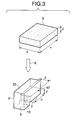
- Fig. 3 is a perspective view which schematically shows the posture of a porous member inserted into a tank container in the compression/insertion process of the porous member in accordance with one embodiment of the present invention.
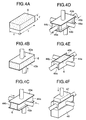
- Figs. 4A, 4B, 4C, 4D, 4E and 4F are views which schematically illustrate the operational flow of one example of the compression insertion method for the porous member to which one embodiment of the present invention is applicable.
- Figs. 5A and 5B are views which schematically illustrate the operational flow of one example of the compression insertion method for the porous member to which one embodiment of the present invention is applicable, and continuously illustrate the operational state shown in Figs. 4A to 4F.
- Fig. 6 is a cross-sectional view which shows the state of the tank after the completion of the porous member compression/insertion process in accordance with one embodiment of the present invention.
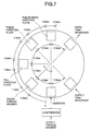
- Fig. 7 is a view which shows the time schedule of each operation when the compression/insertion process for the porous member, and a partition plate fusion process are performed on a production line in accordance with one embodiment of the present invention.
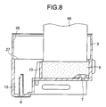
- Fig. 8 is a cross-sectional view which shows the tank in the stage where the porous member is pressed in the partition plate fusion process in accordance with one embodiment of the present invention.
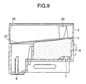
- Fig. 9 is a cross-sectional view which shows the tank in the stage where the partition plate falls in the partition plate fusion process in accordance with one embodiment of the present invention.
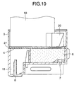
- Fig. 10 is a cross-sectional view which shows the tank in the stage where the partition plate is pressed in the partition plate fusion process in accordance with one embodiment of the present invention.
- Fig. 11 is a cross-sectional view which shows the tank in the stage where the partition plate is fused in the partition plate fusion process in accordance with one embodiment of the present invention.
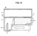
- Fig. 12 is a cross-sectional view which shows the tank in the state after the completion of the partition plate fusion process in accordance with one embodiment of the present invention.
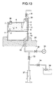
- Fig. 13 is a view which schematically shows the structure of an apparatus used for ink injection process, and the condition in which the ink injection process is executed in accordance with one embodiment of the present invention.
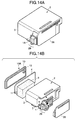
- Figs. 14A and 14B are perspective views which illustrate the structural example of an ink jet cartridge provided with the ink tank unit in accordance with one embodiment of the present invention.
- Fig. 15 is a view which schematically shows one structural example of the ink jet recording apparatus on which the ink jet cartridge represented in Figs. 14A and 14B is installed for use.
- Fig. 16A is a cross-sectional view which shows the structure of the ink tank to which the method of manufacture of the present invention is applicable
- Fig. 16B is a view observed in the direction indicated by an arrow X in Fig. 16A.
- Fig. 17 is a perspective view which shows the shape of the porous member which serves as the negative pressure generating member for the ink tank to which the method of manufacture of the present invention is applicable.
- Fig. 18 is a cross-sectional view which shows the tank for the illustration of problems related to the manufacture of the ink tank represented in Figs. 16A and 16B.
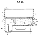
- Fig. 19 is a cross-sectional view which shows the tank for the illustration of problems related to the manufacture of the ink tank represented in Figs. 16A and 16B.
- Fig. 16A is a cross-sectional view which shows the ink jet cartridge to which the method of the present invention for manufacturing an ink is most preferably applicable.
- Fig. 16B is a view which shows in enlargement the portion observed in the direction X indicated by an arrow in Fig. 16A.
- the ink jet cartridge is divided into the ink jet unit 29 provided with an ink jet recording head 1, and the ink tank unit 2 which contains ink to be supplied to the ink jet unit 29.
- the ink tank unit 2 comprises a tank container 3, a covering member 12, and a partition plate 4.
- the structure is arranged to be divided by the partition plate 4 into a first container chamber (porous member containing portion) 5, and a second container chamber (ink containing chamber) 9.
- the first container chamber 5 contains a porous member 6, such as sponge, urethane form, in compressed condition.
- This chamber is provided with the atmosphere communication port 8 through which the air outside is supplied to the porous member 6, and the ink supply port 7 through which ink absorbed in the porous member 6 is supplied to the ink jet recording head 1.
- a filter 14 is provided in order to remove dust particles in the ink tank 2.
- the buffer chamber 15 is formed by the pressure plate 13 that compressively holds the porous member 6. Also, the pressure plate 13 is made functional to keep the porous member 6 in a desired position in the first container chamber 5.
- the second container chamber 9 is communicated with the first container chamber 5 by way of the fine communicative portion 11, and contains only ink to be supplied to the first container chamber 5.
- Ink is injected into the second container chamber 9 through the ink filling port 10 formed on the cover member 12.
- the ink filling port 10 is sealed with an SUS ball 10A in order to prevent ink leakage from the ink injection port 19 (Fig. 16A shows schematically the ink jet cartridge having no ink contained therein).
- the cover member 12 is formed by transparent material, and at the same time, a reflection plate 20 is arranged on the partition plate 4 on the second container chamber 9 side as means for detecting ink remains to sense the presence of ink optically.
- ink in the second container chamber 9 is directly induced from the fine communicative portion 11 to the highly compressed area 6a, that is, the area having a large capillary force, and then, guided to the ink supply port 7 as it is. Owing to this arrangement, it becomes possible to secure the ink passage stably between the ink containing unit and ink supply port irrespective of the posture in distribution for delivery and storage, or the environmental changes.
- the filter 14 provided for the opening portion of the ink supply port 7 in the form of being in contact with the porous member 6 under pressure, meniscus is formed on the filter portion so as to trap micro bubbles which are liable to be supplied from the porous member 6 together with ink. This contributes to making the aforesaid arrangement more effective.
- the buffer chamber 15 is formed with the space inside the first container chamber 5 in the vicinity of the atmosphere communication port 8 so as not to allow the atmosphere communication port 8 to be in contact with the porous member 6, hence providing an advantage that ink leakage from the atmosphere communication port 8 is prevented more reliably. Moreover, even if there is fluctuation in the environmental condition, it becomes possible to prevent ink in the ink tank from leaking through the atmosphere communication port 8.
- the porous member 6 is incorporated in the compressed condition from the opening 25 side of the tank container 3 after the filter 14 has been fixed to the ink supply port 7.
- the partition plate 5 is also incorporated from the opening 25 side of the tank container 3, and fused on a designated position of the inner side of the tank container 3, thus arranging the structure of the first container chamber 5.
- the opening 25 of the tank container 3 is sealed with the cover member 12 to arrange the structure of the second container chamber 9.
- the ink filling port 10 is closed by use of the SUS ball 10A, hence completing the ink tank unit of the ink jet cartridge.
- the shape of the first container chamber is such that the dimension thereof related to substantially parallel direction is larger than the dimension related to the direction orthogonal to the structural surface of the partition plate thus fused.
- the contained porous member is configured so as to be scarcely compressed in the direction orthogonal to the structural surface of the partition plate. Then, in order to exert negative pressure with respect to the ink jet recording head, the compressibility of the porous member to be contained is made larger in the direction substantially parallel to the structural surface of the partition plate.
- the dimension of the porous member used for the aforesaid ink tank is extremely small in the insertion direction as compared with the dimension thereof in the direction orthogonal to the direction in which the member is inserted into the tank container.
- the dimensions X, Y in the direction orthogonal to the insertion direction of the porous member before compression are 49 mm (24 mm after insertion) and 55 mm (37 mm after insertion) respectively.
- the dimension Z in the insertion direction is as extremely small as 20 mm (14.5 mm after insertion) as compared with the dimensions X and Y.
- the porous member is compressed in the direction orthogonal to the direction of tank insertion at the time of the tank being inserted, it is possible for the compressed porous member to become zigzag right on the center thereof, because the dimension of the porous member in the insertion direction is smaller than the one in the insertion direction before being contained. Also, even if the porous member is compressed in good condition and contained in the tank container, the center of the porous member tends to rise due to the configuration of the porous member as described above until the partition plate is fused and bonded. If the central portion of the porous member should become zigzag before the partition plate is fused and bonded in the tank container as shown in Fig.
- FIG. 1 is a view which shows the process flow of the method for manufacturing an ink tank in accordance with one embodiment of the present invention.
- step S1 where the filter 14 is fused and bonded to the ink supply port 7
- step S2 where the porous member 6 is inserted into the tank container 3 in a state of being compressed
- step S3 where the partition plate 4 is fused and bonded in the tank container 3
- step S4 where leakage from the gap between the partition plate 4 and the tank container 3 is checked
- step S5 where the cover member 12 is fusion and bonded to the opening 25 of the tank container 3
- step S6 where leakage from the gap between the opening 25 of the tank container 3, and the cover member 12 is checked
- ink injection step step S7) where ink is injected into the ink containing chamber which is the second container chamber 9.
- Fig. 2 is a cross-sectional view which shows the tank in the filter fusion bonding step.
- the tank container 3 is carried with the opening 25 thereof downward as shown in Fig. 2.
- the filter 14 which is positioned in advance on a fusion bonding horn 41 installed with the leading end thereof being placed upward, and the tank container 3 which has been carried is moved over to the fusion bonding horn 41, thus thermally bonding the filter 14 to the ink supply port 7 provided for the inner wall of the tank container 3.
- this step it becomes possible to suppress the positional variation of the filter 14 and the fusion bonding horn 41, because the fusion bonding horn 41 does not move.
- Fig. 3 is a perspective view which schematically shows the posture in which the porous member is inserted into the tank container in the porous member compression/insertion step.
- the tank container 3 is installed on a jig with the opening 25 of the tank container 3 upward in the porous member compression/insertion step. Then, on the location 42 in the tank container 3 where the porous member is inserted, the flat rectangular parallelepiped porous member 6 is contained in a state of being compressed.
- the porous member 6 Before compression, the porous member 6 is in such a configuration that the dimension Z thereof in the inserting direction is extremely small as compared with the dimensions X and Y thereof in the direction orthogonal to the direction A in which it is inserted into the tank container 3, and that the dimensions X, Y, and Z of the porous member 6 after compression almost correspond to the dimensions X', Y', and Z' of the porous member 6 on the inserted location 42 shown in Fig. 3, but as to the dimension Z, there is almost no compression.
- the dimensions X and Y before compression are 49 mm (24 mm after compression), and 55 mm (37 mm after compression)
- the dimension Z is 20 mm (14.5 mm after compression).
- the reason why the dimension Z is arranged not to be affected much by compression is that although the porous member should be compressed in order to generate negative pressure, there is a fear that the partition plate, which is fused and bonded later, is deformed by the restoring force of the compressed porous member if compression is exerted in the direction of dimension Z. However, compression is slightly exerted in the direction of the dimension Z in order to prevent the creation of gap between the partition plate 4 to be fused and bonded later, and the porous member 6 after having been contained.
- FIGs. 4A to 4F Fis. 5A and 5B are views which schematically illustrate the operational flow of one example of the method for compressing and inserting the porous member 6.
- the porous member 6 which is the state as shown in Fig. 4A, is pressed by pressure plates 43a and 43b to be clamped in the direction of the dimension Z of the porous member 6 as shown in Fig. 4B.
- the porous member 6 is not compressed too much for the reason described earlier.
- the reason why the porous member 6 is pressed despite it is not compressed much is that as compared with the direction of the dimension Z, the dimensions X and Y of the porous member 6 are extremely large in the directions orthogonal to that direction in its shape, and that there is a fear that the porous member is folded in the direction of the dimension Z when it is compressed later in the directions of dimensions X and Y.
- the porous member 6 in the state of being nipped in the direction of the dimension Z is compressed by use of the pressure pates 44a and 44b to put the porous member 6 between them in the direction of the dimension X.
- the porous member 6 is put between the pressure plate 45a and 45b to compress it in the direction of the dimension Y of the porous member 6.
- the configuration is such that the dimension Y is larger than the dimension X, compression is exerted more in the direction of the dimension X than that of Y so that the compression density of the porous member is closer to being uniform after compression. Furthermore, compression is exerted in the order of those having shorter dimensions to stabilize the compressive condition.
- the tank container 3 is installed on a jig or the like with the opening 25 of the tank container 3 upward, and the casing member 46 that has kept the porous member 6 is inserted into the porous member insertion location 42 in the tank container 3.
- Fig. 6 is a cross-sectional view which shows the state of the tank after the completion of the porous member compression/insertion process as described above.
- Fig. 7 is a view which shows the time schedule for each of the operations to be executed in the porous member compression/insertion step and partition plate fusion bonding step on the line of manufacture.
- Fig. 8 to Fig. 12 are cross-sectional views which illustrate the tank in each of the operational conditions in the partition plate fusion bonding step. Now, hereunder, in conjunction with Fig. 8 to Fig. 12, the description will be made of the partition plate fusion bonding step.
- the tank container 3 is fed and carried on the line of manufacture with the opening 25 thereof upward. After 0.3 second, the tank container 3 comes to a stop, and as described earlier, the step of compressing and inserting the porous member 6 is executed (see Fig. 6).
- the tank container 3 having the porous member 6 inserted completely is carried, and as shown in Fig. 8, the porous member 6 is pushed down by the pressure plate 49 lower than the fusion bonding section 27 when the tank container comes to a stop after 0.3 second.
- the tank container 3 is carried.
- the tank container 3 comes to a stop again, and as shown in Fig. 9, the partition plate 4 is dropped down into the tank container 3.
- the tank container 3 having the partition plate 4 completely dropped thereinto is carried.
- the tank container 3 having the partition plate 4 completely pressed down is carried.
- Fig. 12 is a cross-sectional view which shows the tank in a state after the completion of the partition plate fusion bonding step.
- the porous member which has been inserted into the tank container in a state of being compressed, is once pushed thereinto during the period when the partition plate is fused and bonded.
- the reason why this is needed is that once the porous member 6 is expanded and folded as shown in Fig. 18 during the period before the partition plate 4 is fused and bonded after the porous member 6 has been inserted into the tank container 3, the folded condition remains unchanged as shown in Fig. 19 even if it should be pushed down for correction, which makes it impossible to obtain the appropriate compression under which the area existing between the fine communicative portion 11 and the ink supply port 7 is compressed more than the other area.
- the fusion bonding is performed after the press down has been exercised once by use of the pressure plate 50, but the present invention is not necessarily limited thereto. It may be possible to perform the fusion bonding of the partition plate 4, while the porous member 6 being pressed down by use of the fusion bonding horn 51 through the partition plate 4 after the partition plate 4 has dropped down. In other words, it is important to press down the compressed porous member by a pressure jig, a partition plate, or the like before it is allowed to protrude.
- the first container chamber 5 and the second container chamber 9 are allowed to communicate with each other in the location other than the fine communicative portion 11 in the ink tank thus completed.
- the gas-liquid exchange between the first container chamber (porous member containing chamber) 5 and the second container chamber (ink containing chamber) 9 is impeded, and the ink is not induced from the second container chamber 9 to the first container chamber 5 in good condition.
- the ink supply port 7 and the fine communicative portion 11 are closed by use of plugs in the tank container 3 having the partition plate 4 fused and bonded therein as shown in Fig. 12. Then, the space on the first container chamber 5 side is pressurized with the air being sent in from the atmosphere communication port 8. Thus, the inner pressure of the space on the closed first container chamber 5 side is held for a period of 10 second when it has reached 147 kPa. After that, inspection is carried out through the atmosphere communicative part 8 to see whether or not the amount of pressure reduction of the inner pressure in the space of the closed first container chamber 5 side is a designated amount (0.068 kPa) or less.
- pressurization not only pressurization is applicable to the inspection, but also, decompression may be applicable.
- the inspection that uses pressurization makes it easier to find defect fusion bonding, because with pressurization, force is exerted in the direction of peeling off the welded portion between the partition plate 4 and the tank container 3.
- Fig. 16A is a cross-sectional view which shows the tank in a state after the completion of the cover fusion bonding step.
- pressurized inspection is executed as in the first leakage checking step.
- the entire body of the tank container 3 is pressurized with the air being sent from the atmosphere communication port 8 into the tank container 3 having the cover member 12 fused and bonded thereon, while closing the ink supply port 7 and the ink injection port 10 by use of plugs.
- the inner pressure of the closed tank container 3 is held for a period of 10 second when it has reached 147 kPa.
- inspection is carried out through the atmosphere communicative port 8 to see whether or not the amount of pressure reduction of the inner pressure in the closed tank container 3 is a designated amount (0.068 kPa) or less.
- Fig. 13 is a view which schematically shows the structure of an apparatus used for the ink injection step, and the executing condition of the ink injection step as well.
- the tank container 3 is set on a jig 30, and the atmosphere communication nozzle 39 is set at the atmosphere communication port 8, the plug. 36, at the ink supply port 7, the exhaust/injection nozzle 40, at the ink filling port 10, respectively.
- the valve A31 and valve C33 are closed, while the valve B32 is open.
- the valve D34 is open, and ink is filled from the ink pool 38 to the ink quantitative injection device 37 in a required amount.
- the valve D34 is closed, and then, when exhaust is effectuated sufficiently by the pump 35, the valve B32 is closed.
- valve C33 is open, and the designated amount of ink is injected from the ink quantitative injection device 37 into the interior of the tank container 3.
- the valve C33 is closed immediately, and at the same time, the valve A31 is open to release the negative pressure which still remains in the tank.
- the steps from the one in which ink is injected into the tank container 3 to the one in which the valve A31 is open to release the negative pressure remaining in the tank are executed almost continuously in order to avoid the ink in the tank, which tends to become equilibrated, from flowing out into the buffer chamber 15.
- valve A31 is closed again, and the exhaust/injection nozzle 40 is removed from the ink filling port 10.
- the ink filling port 10 is sealed with the SUS ball 10A.
- the atmosphere communication nozzle 39 is removed from the atmosphere communicative port 8.
- the plug 36 is removed from the ink supply port 7, and the tank container 3 is removed from the jig 30 to complete the ink injection step by the application of the decompression method.
- the ink flow is not affected by gravitation, nor by the compression of the porous member.
- the ink flows in the direction Z in Fig. 13, and then, in the direction X, hence making it possible to facilitate filling ink sufficiently even in the area 6a which exists between the ink supply port 7 and the fine communicative portion 11 of the porous member 6.
- this step is not necessarily limited to the adoption of the method using decompression injection. It may be possible to adopt the method that uses pressurized injection.
- the injection method that uses decompression as described in the example hereof should be more preferable, because it becomes possible then to supply ink sufficiently to the area 6a where ink should be retained even when the ink that has no surfactant with lower permeability is to be used (usually, when black ink is used, no surfactant is contained in the composition thereof in order to make printed characters clearer by use of such ink).
- the ink jet cartridge of this example is in a shape in which the linearly edge portion of the ink jet unit 29 slightly protrudes from the front face of the ink tank unit 2.
- the ink jet cartridge comprises the cover member 12; the SUS ball 10A that seals the ink filling port 10; the partition plate 4 provided with the fine communicative portion 11; the tank container 3 that contains the porous member 6 to retain ink (the porous member 6 shown in Fig.
- the ink jet unit 29 for supplying ink from the ink supply port 7 provided for the tank container 3 to the ink jet recording head 1 through joint pipe (not shown), which is, at the same time, provided with the portion to transmit signals from the ink jet recording apparatus main body; and the head cover 28 that protects the ink jet unit 29.
- the ink jet recording head 1 performs recording by use of electrothermal converting devices that generate thermal energy for creating film boiling in ink in accordance with electric signals.
- Fig. 15 is a view which schematically shows one structural example of the ink jet recording apparatus to which the ink jet cartridge of the aforesaid structure is mounted and made applicable.
- the ink jet cartridge 601 structured as above is mounted on the carriage 607 that engages with the spiral groove 606 of a lead screw 605 rotating through driving power transmission gears 603 and 604 which are interlocked with the regular and reverse rotations of a driving motor 602.
- the ink jet cartridge 601 reciprocates by the driving power of the driving motor 602 together with the carriage 607 along a guide 608 in the directions indicated by arrows a and b.
- the ink jet recording apparatus 600 is provided with recording medium carrying means (not shown) for carrying a printing sheet P serving as the recording medium that receives liquid, such as ink, discharged from the ink jet cartridge 601. Then, the sheet pressure plate 610, which is used for carrying the printing sheet P on a platen 609 by means for carrying recording medium, is arranged to press the printing sheet P to the platen 609 over the traveling direction of the carriage 607.
- Photocouplers 611 and 612 are arranged in the vicinity of one end of the lead screw 605.
- the photocouplers 611 and 612 are the means for detecting home position which switches the rotational directions of the driving motor 602 by recognizing the presence of the lever 607a of the carriage 607 in the working region of the photocouplers 611 and 612.
- a supporting member 613 is arranged for supporting the cap member 614 that covers the front end having the discharge ports of the ink jet cartridge 601.
- the ink suction means 615 that sucks ink retained in the interior of the cap member 614 when idle discharges or the like are made from the ink jet cartridge 601. With the ink suction means 615, suction recoveries of the ink jet cartridge 601 are performed through the opening portion of the cap member 614.
- a main body supporting member 619 is provided.
- a movable member 618 is movably supported in the forward and backward directions, that is, the direction at right angles to the traveling directions of the carriage 607.
- a cleaning blade 617 is installed on the movable member 618.
- the mode of the cleaning blade 617 is not necessarily limited to this arrangement. Any known cleaning blade of some other modes may be applicable.
- the lever 620 which initiates suction when the ink suction means 615 operates its suction recovery.
- the lever 620 moves along the movement of the cam 621 that engages with the carriage 607.
- the movement thereof is controlled by known transmission means such as the clutch that switches the driving power of the driving motor 602.
- the ink jet recording controller which deals with the supply of signals to the heat generating elements provided for the ink jet cartridge 601, as well as the driving controls of each of the mechanisms described earlier, is provided for the recording apparatus main body side, and not shown in Fig. 15.
- the aforesaid recording medium carrying means carries a printing sheet P on the platen 609, and the ink jet cartridge 601 reciprocates over the entire width of the printing sheet P.
- ink recording liquid
- driving signal supply means not shown
- the recording medium which is used for a recording apparatus of the kind for the adhesion of liquid, such as ink, thereon, it is possible to use, as an objective medium, various kinds of paper and OHP sheets; plastic materials used for a compact disc, ornamental board, and the like; cloths; metallic materials, such as aluminum, copper; leather materials, such as cowhide, pigskin, and artificial leathers; wood materials, such as wood, plywood; bamboo materials; ceramic materials, such as tiles; and three-dimensional structure, such as sponge, among some others.
- a printing apparatus for recording on various kinds of paper, OHP sheet, and the like a recording apparatus for use of plastic materials which records on a compact disc, and other plastic materials; a recording apparatus for use of metallic materials that records on metallic plates; a recording apparatus for use of leather materials that records on leathers; a recording apparatus for use of wood materials that records on woods; a recording apparatus for use of ceramics that records on ceramic materials; and a recording apparatus for recording a three-dimensional netting structures, such as sponge, or a textile printing apparatus or the like that records on cloths.
- discharging liquid usable for any one of these liquid discharge apparatuses it should be good enough if only such liquid can be used matching with the respective recording mediums and recording conditions accordingly.
- the porous member After the porous member has been inserted into the container in a state of being compressed, the porous member is once pushed in during the period when the partition plate is fixed to the opening of the container, it becomes possible to prevent the porous member to be expanded and folded, hence obtaining appropriate compression in the porous member thus contained.
- a method for manufacturing an ink tank comprises the steps of supplying an container having an opening, inserting a porous member into the opening of the container in a state of being compressed, and holding the porous member in the compressed state by fixing a plate member to the opening of the container, and the porous member being in a compressed shape more in the direction substantially orthogonal to the direction of the insertion when the porous member is compressed in the inserting direction into the opening.
- the porous member when compressing the porous member, the porous member is clamped in the same direction as the inserting direction so as not to allow the porous member to be deformed in the inserting direction, and in such state, the porous member is compressed in the direction substantially orthogonal to the inserting direction, Therefore, even if the dimension of the porous member is sufficiently small in the inserting direction before compression as compared with the one in the direction substantially orthogonal to the inserting direction, there is no possibility that the compressed porous member is folded right on the center thereof, hence making it possible to insert it into the tank container in good condition.
Landscapes
- Engineering & Computer Science (AREA)
- Manufacturing & Machinery (AREA)
- Ink Jet (AREA)
Abstract
A method for manufacturing an ink tank comprises
the steps of supplying an container having an opening,
inserting a porous member into the opening of the
container in a state of being compressed, and
holding the porous member in the compressed state by
fixing a plate member to the opening of the container,
and the porous member being in a compressed shape more
in the direction substantially orthogonal to the
direction of the insertion when the porous member is
compressed in the inserting direction into the opening.
In this method, when compressing the porous member, the
porous member is clamped in the same direction as the
inserting direction so as not to allow the porous
member to be deformed in the inserting direction, and
in such state, the porous member is compressed in the
direction substantially orthogonal to the inserting
direction, Therefore, even if the dimension of the
porous member is sufficiently small in the inserting
direction before compression as compared with the one
in the direction substantially orthogonal to the
inserting direction, there is no possibility that the
compressed porous member is folded right on the center
thereof, hence making it possible to insert it into the
tank container in good condition.
Description
- The present invention relates to a method for manufacturing an ink tank that retains ink for use of ink jet recording. Also, the present invention is applicable to a copying machine, a recording equipment, such as a facsimile, a communication equipment, an office equipment, a complex equipment, a printer, and the like that uses the ink jet technologies.
- Here, in the specification hereof, the term "recording" means not only meaningful images, such as characters, but also, means such meaningless images as patterned ones. The recording equipment includes all kinds of information processing apparatuses or the printer that serves as the output equipment thereof. Related Background Art
- As the output equipment of a personal computer, a copying machine, a facsimile, or the like, a recording apparatus of ink jet type is used. As one example of recording means applicable to an ink jet recording apparatus of the kind, there is an ink jet cartridge in which an ink jet recording head is integrally formed with an ink tank that retains ink to be supplied to the ink jet recording head, which is arranged to be exchangeable with respect to the scanning carriage provided for the apparatus.
- The ink tank of an ink jet cartridge has in the interior thereof a negative pressure generating element retaining ink therein, which is arranged to exert a desired negative pressure with respect to the recording head. Here, as a structure capable of using contained ink without waste, while exerting appropriate negative pressure as an ink tank, there is disclosed a structure in the specification of Japanese Patent Laid-Open Application No. 07-125232, for example, wherein the interior of the ink tank is divided into almost halves by use of a wall member, and then, a communicative portion is provided between the separation wall and the bottom thereof to supply ink, while a porous member is contained in a chamber (a first container chamber) on the side where the recording head is installed, and ink is directly contained in the other chamber (a second container chamber).
- Further, in the specification of Japanese Patent Laid-Open Application No. 08-230209 filed by the applicant hereof, a structure is disclosed in which the aforesaid structure is made applicable to an ink jet cartridge having a recording head provided integrally therefor so as to be more adaptable for change of postures in the delivery distribution, as well as for the environmental changes.
- As described above, the applicant hereof has proposed the ink tank structure which is excellent in demonstrating the capability of stable ink supply against the condition of delivery distribution and the environmental changes. For the sufficient demonstration of such function of tank, the following aspects are taken into consideration for the implementation thereof.
- In other words, the shape of the first container chamber is such that the dimension in the directions substantially in parallel is made larger than the dimension in the direction orthogonal to the structural plane of the partition plate to be fused and bonded so that the area of the porous member contained in the first container chamber, which exists between the fine communicative portion and the ink supply port connected with a recording head, is easily compressed more than the other area. Moreover, with the structure in which the first container chamber is formed by fusing and bonding the partition plate after the porous member has been contained in the tank container, the contained porous member is in such a configuration that it is scarcely compressed in the direction orthogonal to the structural plane of the partition plate, that is, the restoring force of the compressed porous member does not work greatly in the direction in which the fusion bonded partition plate is compressed to the ink containing chamber side. As a result, the compressivity of the contained porous member is made greater in the direction substantially parallel to the structural plane of the partition plate so as to exert negative pressure with respect to the ink jet recording head.
- Along with this arrangement, the porous member is in such a shape before compression that the dimension thereof in the direction of its insertion into the tank container is extremely small as compared with the one in the direction orthogonal to the inserting direction.
- However, when the porous member is compressed in the direction orthogonal to the inserting direction at the time of being inserted into the tank, there is a possibility that the compressed porous member is folded right on the center thereof, because the dimension of the porous member is smaller in the direction of insertion than the one in the direction orthogonal to the inserting direction before being contained in the tank. As a result, it becomes difficult to insert the porous member into the tank container in good condition.
- With a view to solving the problems encountered in the manufacture of tank as described above, it is the main object of the invention to provide a method for manufacturing an ink tank capable of containing in a tank container a porous member of such a shape that the dimension thereof is extremely large in the direction orthogonal to the direction of insertion into the container as compared with the dimension in the inserting direction by exerting compression greatly on the dimension in the direction orthogonal to the inserting direction, while scarcely exerting compression on the dimension in the inserting direction so as to obtain appropriate compression for generating negative pressure in the tank container.
- Also, it is another object of the invention to provide a method for manufacturing an ink tank capable of maintaining the ink supply capability stably irrespective of the condition of delivery distribution and the environmental changes.
- It is still another object of the invention to provide an ink tank manufactured by the method of manufacture described above, an ink jet cartridge provided with such ink tank, and an ink jet recording apparatus having such ink tank mounted thereon.
- In order to achieve the above objects, the method of the present invention for manufacturing an ink tank comprises the steps of supplying an container having an opening; inserting a porous member into the opening of the container in a state of being compressed; and holding the porous member in the compressed state by fixing a plate member to the opening of the container, and the porous member being in a compressed shape more in the direction substantially orthogonal to the direction of the insertion when the porous member is compressed in the inserting direction into the opening. In this method, when compressing the porous member, the porous member is clamped in the same direction as the inserting direction so as not to allow the porous member to be deformed in the inserting direction, and in such state, the porous member is compressed in the direction substantially orthogonal to the inserting direction.
- Further, when fixing the plate member to the opening, the porous member inserted into the opening should preferably be pushed in once.
- The porous member is in a shape of flat rectangular parallelepiped having small dimension in the inserting direction as compared with the dimension in the direction substantially orthogonal to the inserting direction into the opening, and the dimension of the porous member in the inserting direction is slightly larger than the dimension of the opening in the inserting direction.
- It is preferable to compress the porous member more in the direction X than the direction Y when the dimension of the porous member of flat rectangular parallelepiped is larger in the direction Y than the dimension in the direction X in the two axial X and Y directions orthogonal to the inserting direction.
- Also, for the ink tank which is used for the method of manufacture described above, the plate member is a partition plate for dividing the interior of the container into a first container chamber and a second container chamber, and the porous member is contained in the first container chamber; the first container chamber is provided with an ink supply port arranged on the plane facing the partition plate, and an atmosphere communication port; the partition plate is provided with a fine communicative portion in the area facing substantially to the ink supply port; and the area of the porous member existing between the ink supply port and the fine communicative portion is held in higher compression than the other area.
- Also, to the present invention, the ink jet cartridge belongs, which comprises an ink jet head being bonded to the ink supply port of ink tank referred to in the preceding paragraph.
- For the aforesaid ink jet head, it is applicable to adopt the one which is provided with electrothermal converting devices to generate ink discharge energy for discharging ink from the discharge ports by utilization of film boiling created in ink by thermal energy applied by the electrothermal converting devices.
- Also, the present invention includes the ink jet recording apparatus provided with an ink jet cartridge which is made detachably mountable on the recording apparatus main body.
- In accordance with the present invention, it is arranged to clamp the porous member in the inserting direction so as not to allow the porous member to be deformed in the inserting direction when inserting it into the container, and in this state, the porous member is compressed in the direction substantially orthogonal to the inserting direction. Therefore, even if the dimension of the porous member is sufficiently small in the inserting direction before compression as compared with the one in the direction substantially orthogonal to the inserting direction, there is no possibility that the compressed porous member is folded right on the center thereof, hence making it possible to insert it into the tank container in good condition.
- Also, after the porous member has been inserted into the container in a state of being compressed, the porous member is pushed in once during the period until the palate member is fixed to the opening of the container, hence preventing the porous member from being expanded and folded to make it possible to obtain appropriate compression in the porous member thus contained.
- Fig. 1 is a flow diagram which shows a method for manufacturing an ink tank in accordance with one embodiment of the present invention.
- Fig. 2 is a cross-sectional view which shows a tank for the illustration of a filter welding process in accordance with one embodiment of the present invention.
- Fig. 3 is a perspective view which schematically shows the posture of a porous member inserted into a tank container in the compression/insertion process of the porous member in accordance with one embodiment of the present invention.
- Figs. 4A, 4B, 4C, 4D, 4E and 4F are views which schematically illustrate the operational flow of one example of the compression insertion method for the porous member to which one embodiment of the present invention is applicable.
- Figs. 5A and 5B are views which schematically illustrate the operational flow of one example of the compression insertion method for the porous member to which one embodiment of the present invention is applicable, and continuously illustrate the operational state shown in Figs. 4A to 4F.
- Fig. 6 is a cross-sectional view which shows the state of the tank after the completion of the porous member compression/insertion process in accordance with one embodiment of the present invention.
- Fig. 7 is a view which shows the time schedule of each operation when the compression/insertion process for the porous member, and a partition plate fusion process are performed on a production line in accordance with one embodiment of the present invention.
- Fig. 8 is a cross-sectional view which shows the tank in the stage where the porous member is pressed in the partition plate fusion process in accordance with one embodiment of the present invention.
- Fig. 9 is a cross-sectional view which shows the tank in the stage where the partition plate falls in the partition plate fusion process in accordance with one embodiment of the present invention.
- Fig. 10 is a cross-sectional view which shows the tank in the stage where the partition plate is pressed in the partition plate fusion process in accordance with one embodiment of the present invention.
- Fig. 11 is a cross-sectional view which shows the tank in the stage where the partition plate is fused in the partition plate fusion process in accordance with one embodiment of the present invention.
- Fig. 12 is a cross-sectional view which shows the tank in the state after the completion of the partition plate fusion process in accordance with one embodiment of the present invention.
- Fig. 13 is a view which schematically shows the structure of an apparatus used for ink injection process, and the condition in which the ink injection process is executed in accordance with one embodiment of the present invention.
- Figs. 14A and 14B are perspective views which illustrate the structural example of an ink jet cartridge provided with the ink tank unit in accordance with one embodiment of the present invention.
- Fig. 15 is a view which schematically shows one structural example of the ink jet recording apparatus on which the ink jet cartridge represented in Figs. 14A and 14B is installed for use.
- Fig. 16A is a cross-sectional view which shows the structure of the ink tank to which the method of manufacture of the present invention is applicable, and Fig. 16B is a view observed in the direction indicated by an arrow X in Fig. 16A.
- Fig. 17 is a perspective view which shows the shape of the porous member which serves as the negative pressure generating member for the ink tank to which the method of manufacture of the present invention is applicable.
- Fig. 18 is a cross-sectional view which shows the tank for the illustration of problems related to the manufacture of the ink tank represented in Figs. 16A and 16B.
- Fig. 19 is a cross-sectional view which shows the tank for the illustration of problems related to the manufacture of the ink tank represented in Figs. 16A and 16B.
- Hereinafter, with reference to the accompanying drawings, the description will be made of the embodiments in accordance with the present invention.
- At first, while describing the ink tank to which the method of the present invention for manufacturing an ink tank is most preferably applicable, the background art will be described with respect to the porous member inserted into such ink tank. Fig. 16A is a cross-sectional view which shows the ink jet cartridge to which the method of the present invention for manufacturing an ink is most preferably applicable. Fig. 16B is a view which shows in enlargement the portion observed in the direction X indicated by an arrow in Fig. 16A.
- In accordance with Figs. 16A and 16B, the ink jet cartridge is divided into the
ink jet unit 29 provided with an inkjet recording head 1, and theink tank unit 2 which contains ink to be supplied to theink jet unit 29. Here, theink tank unit 2 comprises atank container 3, a coveringmember 12, and apartition plate 4. Then, the structure is arranged to be divided by thepartition plate 4 into a first container chamber (porous member containing portion) 5, and a second container chamber (ink containing chamber) 9. Thefirst container chamber 5 contains aporous member 6, such as sponge, urethane form, in compressed condition. This chamber is provided with theatmosphere communication port 8 through which the air outside is supplied to theporous member 6, and theink supply port 7 through which ink absorbed in theporous member 6 is supplied to the inkjet recording head 1. For theink supply port 7, afilter 14 is provided in order to remove dust particles in theink tank 2. - There is a
buffer chamber 15 between theatmosphere communication chamber 8 and theporous member 6. Thebuffer chamber 15 is formed by thepressure plate 13 that compressively holds theporous member 6. Also, thepressure plate 13 is made functional to keep theporous member 6 in a desired position in thefirst container chamber 5. - On the position of the
partition plate 4 that faces theink supply port 7 substantially, there is provided a finecommunicative portion 11 that penetrates thepartition plate 4, and this finecommunicative portion 11 is arranged to be away from theboundary 4A between the inner walls of thetank container 3 and thepartition plate 4. - The
second container chamber 9 is communicated with thefirst container chamber 5 by way of the finecommunicative portion 11, and contains only ink to be supplied to thefirst container chamber 5. Ink is injected into thesecond container chamber 9 through theink filling port 10 formed on thecover member 12. After the injection of ink, theink filling port 10 is sealed with anSUS ball 10A in order to prevent ink leakage from the ink injection port 19 (Fig. 16A shows schematically the ink jet cartridge having no ink contained therein). - In this respect, the
cover member 12 is formed by transparent material, and at the same time, areflection plate 20 is arranged on thepartition plate 4 on thesecond container chamber 9 side as means for detecting ink remains to sense the presence of ink optically. - With the structure thus arranged, the
area 6a of theporous member 6 contained in thefirst container chamber 5 in a state of being compressed, which is squeezed between the finecommunicative portion 11 and theink supply port 7, is compressed more than theother area 6b, because the circumference of theink supply port 7 protrudes to thefirst container chamber 5 side. As a result, ink in thesecond container chamber 9 is directly induced from the finecommunicative portion 11 to the highlycompressed area 6a, that is, the area having a large capillary force, and then, guided to theink supply port 7 as it is. Owing to this arrangement, it becomes possible to secure the ink passage stably between the ink containing unit and ink supply port irrespective of the posture in distribution for delivery and storage, or the environmental changes. Also, with thefilter 14 provided for the opening portion of theink supply port 7 in the form of being in contact with theporous member 6 under pressure, meniscus is formed on the filter portion so as to trap micro bubbles which are liable to be supplied from theporous member 6 together with ink. This contributes to making the aforesaid arrangement more effective. In addition, thebuffer chamber 15 is formed with the space inside thefirst container chamber 5 in the vicinity of theatmosphere communication port 8 so as not to allow theatmosphere communication port 8 to be in contact with theporous member 6, hence providing an advantage that ink leakage from theatmosphere communication port 8 is prevented more reliably. Moreover, even if there is fluctuation in the environmental condition, it becomes possible to prevent ink in the ink tank from leaking through theatmosphere communication port 8. - Also, when manufacturing such an ink tank unit as described above, the
porous member 6 is incorporated in the compressed condition from theopening 25 side of thetank container 3 after thefilter 14 has been fixed to theink supply port 7. Then, thepartition plate 5 is also incorporated from theopening 25 side of thetank container 3, and fused on a designated position of the inner side of thetank container 3, thus arranging the structure of thefirst container chamber 5. Then, theopening 25 of thetank container 3 is sealed with thecover member 12 to arrange the structure of thesecond container chamber 9. Further, subsequent to having injected ink into thesecond container chamber 9 through theink filling port 10 of thecover member 12, theink filling port 10 is closed by use of theSUS ball 10A, hence completing the ink tank unit of the ink jet cartridge. - Here, for the aforesaid ink jet cartridge, the shape of the first container chamber is such that the dimension thereof related to substantially parallel direction is larger than the dimension related to the direction orthogonal to the structural surface of the partition plate thus fused. Moreover, the contained porous member is configured so as to be scarcely compressed in the direction orthogonal to the structural surface of the partition plate. Then, in order to exert negative pressure with respect to the ink jet recording head, the compressibility of the porous member to be contained is made larger in the direction substantially parallel to the structural surface of the partition plate.
- Therefore, before insertion, the dimension of the porous member used for the aforesaid ink tank is extremely small in the insertion direction as compared with the dimension thereof in the direction orthogonal to the direction in which the member is inserted into the tank container. As shown in Fig. 17, for example, if the shape of the porous member is flat rectangular parallelepiped, the dimensions X, Y in the direction orthogonal to the insertion direction of the porous member before compression are 49 mm (24 mm after insertion) and 55 mm (37 mm after insertion) respectively. Then, the dimension Z in the insertion direction is as extremely small as 20 mm (14.5 mm after insertion) as compared with the dimensions X and Y.
- However, if the porous member is compressed in the direction orthogonal to the direction of tank insertion at the time of the tank being inserted, it is possible for the compressed porous member to become zigzag right on the center thereof, because the dimension of the porous member in the insertion direction is smaller than the one in the insertion direction before being contained. Also, even if the porous member is compressed in good condition and contained in the tank container, the center of the porous member tends to rise due to the configuration of the porous member as described above until the partition plate is fused and bonded. If the central portion of the porous member should become zigzag before the partition plate is fused and bonded in the tank container as shown in Fig. 18, the zigzag condition remains unchanged even after the partition plate having been fused and bonded as shown in Fig. 19. As a result, it becomes impossible to obtain any appropriate compression which enables the area existing between the fine communicative portion and the ink supply port to be compressed more than the other area in the contained porous member.
- Now, in conjunction with Fig. 1, the description will be made of the method for manufacturing an ink tank in accordance with the present invention. Fig. 1 is a view which shows the process flow of the method for manufacturing an ink tank in accordance with one embodiment of the present invention.
- For the manufacture of the ink tank unit shown in Figs. 16A and 16B, there are roughly the steps as shown in Fig. 1, comprising: the filter fusion bonding step (step S1) where the
filter 14 is fused and bonded to theink supply port 7; the porous member compression/insertion step (step S2) where theporous member 6 is inserted into thetank container 3 in a state of being compressed; the partition plate fusion bonding step (step S3) where thepartition plate 4 is fused and bonded in thetank container 3; a first leakage checking step (step S4) where leakage from the gap between thepartition plate 4 and thetank container 3 is checked; the cover fusion bonding step (step S5) where thecover member 12 is fusion and bonded to theopening 25 of thetank container 3; a second leakage checking step (step S6) where leakage from the gap between the opening 25 of thetank container 3, and thecover member 12 is checked; and ink injection step (step S7) where ink is injected into the ink containing chamber which is thesecond container chamber 9. Each of these steps is executed in the process of assembling thefilter 14, theporous member 6, thepartition plate 4, and thecover member 12 one after another on thetank container 3 being carried, while, for example, thetank container 3 is arranged to flow as a work on an automatic assembling line. - Now, hereunder, these steps are described in detail one after another.
- Fig. 2 is a cross-sectional view which shows the tank in the filter fusion bonding step. In the filter fusion bonding step, the
tank container 3 is carried with theopening 25 thereof downward as shown in Fig. 2. Then, with thefilter 14 which is positioned in advance on afusion bonding horn 41 installed with the leading end thereof being placed upward, and thetank container 3 which has been carried is moved over to thefusion bonding horn 41, thus thermally bonding thefilter 14 to theink supply port 7 provided for the inner wall of thetank container 3. Here, in this step, it becomes possible to suppress the positional variation of thefilter 14 and thefusion bonding horn 41, because thefusion bonding horn 41 does not move. - Fig. 3 is a perspective view which schematically shows the posture in which the porous member is inserted into the tank container in the porous member compression/insertion step. As shown in Fig. 3, the
tank container 3 is installed on a jig with theopening 25 of thetank container 3 upward in the porous member compression/insertion step. Then, on thelocation 42 in thetank container 3 where the porous member is inserted, the flat rectangular parallelepipedporous member 6 is contained in a state of being compressed. - Before compression, the
porous member 6 is in such a configuration that the dimension Z thereof in the inserting direction is extremely small as compared with the dimensions X and Y thereof in the direction orthogonal to the direction A in which it is inserted into thetank container 3, and that the dimensions X, Y, and Z of theporous member 6 after compression almost correspond to the dimensions X', Y', and Z' of theporous member 6 on the insertedlocation 42 shown in Fig. 3, but as to the dimension Z, there is almost no compression. For example, as shown in Fig. 17, whereas the dimensions X and Y before compression are 49 mm (24 mm after compression), and 55 mm (37 mm after compression), the dimension Z is 20 mm (14.5 mm after compression). The reason why the dimension Z is arranged not to be affected much by compression is that although the porous member should be compressed in order to generate negative pressure, there is a fear that the partition plate, which is fused and bonded later, is deformed by the restoring force of the compressed porous member if compression is exerted in the direction of dimension Z. However, compression is slightly exerted in the direction of the dimension Z in order to prevent the creation of gap between thepartition plate 4 to be fused and bonded later, and theporous member 6 after having been contained. - Now, the specific example is described as to the method for compressing and inserting the porous member. Figs. 4A to 4F, Fis. 5A and 5B are views which schematically illustrate the operational flow of one example of the method for compressing and inserting the
porous member 6. As shown in Figs. 4A to 4F, Figs. 5A and 5B, theporous member 6, which is the state as shown in Fig. 4A, is pressed bypressure plates porous member 6 as shown in Fig. 4B. At this juncture, theporous member 6 is not compressed too much for the reason described earlier. Also, the reason why theporous member 6 is pressed despite it is not compressed much is that as compared with the direction of the dimension Z, the dimensions X and Y of theporous member 6 are extremely large in the directions orthogonal to that direction in its shape, and that there is a fear that the porous member is folded in the direction of the dimension Z when it is compressed later in the directions of dimensions X and Y. - Further, as shown in Fig. 4C, the
porous member 6 in the state of being nipped in the direction of the dimension Z is compressed by use of thepressure pates porous member 6 between them in the direction of the dimension X. Then, as shown in Fig. 4D, theporous member 6 is put between thepressure plate porous member 6. For the present example, since the configuration is such that the dimension Y is larger than the dimension X, compression is exerted more in the direction of the dimension X than that of Y so that the compression density of the porous member is closer to being uniform after compression. Furthermore, compression is exerted in the order of those having shorter dimensions to stabilize the compressive condition. - After that, as shown in Fig. 4E, the
pressure plates porous member 6, which has been compressed in the directions of dimensions X and Y by thepressure plates pressure plate 47 as shown in Fig. 4F to be kept in thecasing member 46 having the contours to be fitted in the porousmember insertion location 42 the dimensions of which are within those X' and Y' shown in Fig. 3. - Further, as shown in Fig. 5A, the
tank container 3 is installed on a jig or the like with theopening 25 of thetank container 3 upward, and thecasing member 46 that has kept theporous member 6 is inserted into the porousmember insertion location 42 in thetank container 3. - Lastly, as shown in Fig. 5B, the casing
member 46 is withdrawn from thetank container 3 with theporous member 6 being conditioned to be pressed by thepressure plate 48. After that, the pressurized condition by thepressure plate 48 is released. - Fig. 6 is a cross-sectional view which shows the state of the tank after the completion of the porous member compression/insertion process as described above.
- In this respect, such compression/insertion method as above has been described as a specific example, but it may be possible to apply the method proposed by the applicant hereof in the specification of Japanese Patent Laid-Open Application No. 07-314727 or the method disclosed in the specification of Japanese Patent Laid-Open Application No. 05-463. In accordance with the method proposed in the specification of the former Laid-Open Application, when a porous member is compressed and inserted by use of a hand for use of clamping, the inserted porous member has been already positioned on a designated inserting location in a tank container, and then, the hand for use of clamping is withdrawn with the porous member in such a state being pressed as it is. As a result, there occurs any forcibly frictional relation between the porous member and the inner wall of the container, makes it possible to contain the porous member more preferable condition without the occurrence of wrinkles, turning ups, or the like.
- However, irrespective of any method that may be adopted, it is important to press a porous member as in the present invention so that it is not deformed in the direction in which it is inserted if the porous member is in a shape that the dimension thereof is extremely large in the direction orthogonal to the container inserting direction as compared with the one in the container inserting direction, and then, negative pressure is exerted by the greater compression on the dimension in the direction orthogonal to the container inserting direction, while scarcely compressing the dimension in the container inserting direction.
- Fig. 7 is a view which shows the time schedule for each of the operations to be executed in the porous member compression/insertion step and partition plate fusion bonding step on the line of manufacture. Also, Fig. 8 to Fig. 12 are cross-sectional views which illustrate the tank in each of the operational conditions in the partition plate fusion bonding step. Now, hereunder, in conjunction with Fig. 8 to Fig. 12, the description will be made of the partition plate fusion bonding step.
- At first, the
tank container 3 is fed and carried on the line of manufacture with theopening 25 thereof upward. After 0.3 second, thetank container 3 comes to a stop, and as described earlier, the step of compressing and inserting theporous member 6 is executed (see Fig. 6). - Then, the
tank container 3 having theporous member 6 inserted completely is carried, and as shown in Fig. 8, theporous member 6 is pushed down by thepressure plate 49 lower than thefusion bonding section 27 when the tank container comes to a stop after 0.3 second. - Then, with the completion of pushing down of the
porous member 6, thetank container 3 is carried. Here, it takes 1.2 second for the carrier that has come to a stop to push down the porous member, and begins to carry the tank container again. After 0.3 second since then, thetank container 3 comes to a stop again, and as shown in Fig. 9, thepartition plate 4 is dropped down into thetank container 3. - Next, the
tank container 3 having thepartition plate 4 completely dropped thereinto is carried. Here, it takes 1.2 second for the carrier that has come to a stop to enable the partition plate to be dropped down, and begins to carry the tank container again. After 0.3 second since then, thetank container 3 comes to a stop again, and as shown in Fig. 10, thepartition plate 4 is pressed by use of thepressure plate 50 until it is regulated in thefusion bonding section 27 in order to correct the posture of thepartition plate 4 in thetank container 3. Here, it is desirable to arrange a configuration so that thepressure plate 50 can also press down thepartition plate 4 from above thereflection plate 20 installed therefor. - Next, the
tank container 3 having thepartition plate 4 completely pressed down is carried. Here, it takes 1.2 second for the carrier that has come to a stop to enable the partition plate to be pressed down, and begins to carry the tank container again. After 0.3 second since then, thetank container 3 comes to a stop again, and as shown in Fig. 11, thepartition plate 4 is fused and bonded by use of thefusion bonding horn 51 for ultrasonic welding use to thefusion bonding section 27 of thetank container 3. - Fig. 12 is a cross-sectional view which shows the tank in a state after the completion of the partition plate fusion bonding step.
- In the steps described above, the porous member, which has been inserted into the tank container in a state of being compressed, is once pushed thereinto during the period when the partition plate is fused and bonded. The reason why this is needed is that once the
porous member 6 is expanded and folded as shown in Fig. 18 during the period before thepartition plate 4 is fused and bonded after theporous member 6 has been inserted into thetank container 3, the folded condition remains unchanged as shown in Fig. 19 even if it should be pushed down for correction, which makes it impossible to obtain the appropriate compression under which the area existing between the finecommunicative portion 11 and theink supply port 7 is compressed more than the other area. - In accordance with the present embodiment, the fusion bonding is performed after the press down has been exercised once by use of the
pressure plate 50, but the present invention is not necessarily limited thereto. It may be possible to perform the fusion bonding of thepartition plate 4, while theporous member 6 being pressed down by use of thefusion bonding horn 51 through thepartition plate 4 after thepartition plate 4 has dropped down. In other words, it is important to press down the compressed porous member by a pressure jig, a partition plate, or the like before it is allowed to protrude. - If the fusion bonding of the partition plate is insufficient in the previous step, the
first container chamber 5 and thesecond container chamber 9 are allowed to communicate with each other in the location other than the finecommunicative portion 11 in the ink tank thus completed. As a result, the gas-liquid exchange between the first container chamber (porous member containing chamber) 5 and the second container chamber (ink containing chamber) 9 is impeded, and the ink is not induced from thesecond container chamber 9 to thefirst container chamber 5 in good condition. - Therefore, in the first leakage checking step after the partition plate fusion bonding step, the
ink supply port 7 and the finecommunicative portion 11 are closed by use of plugs in thetank container 3 having thepartition plate 4 fused and bonded therein as shown in Fig. 12. Then, the space on thefirst container chamber 5 side is pressurized with the air being sent in from theatmosphere communication port 8. Thus, the inner pressure of the space on the closedfirst container chamber 5 side is held for a period of 10 second when it has reached 147 kPa. After that, inspection is carried out through the atmospherecommunicative part 8 to see whether or not the amount of pressure reduction of the inner pressure in the space of the closedfirst container chamber 5 side is a designated amount (0.068 kPa) or less. In this step, not only pressurization is applicable to the inspection, but also, decompression may be applicable. However, the inspection that uses pressurization makes it easier to find defect fusion bonding, because with pressurization, force is exerted in the direction of peeling off the welded portion between thepartition plate 4 and thetank container 3. - In the cover fusion bonding step, the
cover member 12 is fused and bonded to theopening 25 of thetank container 3 by means of ultrasonic fusion bonding. Fig. 16A is a cross-sectional view which shows the tank in a state after the completion of the cover fusion bonding step. - If the fusion bonding of the cover member is insufficient in the previous step, ink leakage takes place in the ink injection step to be described later or in the completed ink tank.
- Therefore, in the second leakage checking step after the cover fusion bonding step, pressurized inspection is executed as in the first leakage checking step. In other words, as shown in Fig. 16A, the entire body of the
tank container 3 is pressurized with the air being sent from theatmosphere communication port 8 into thetank container 3 having thecover member 12 fused and bonded thereon, while closing theink supply port 7 and theink injection port 10 by use of plugs. Thus, the inner pressure of theclosed tank container 3 is held for a period of 10 second when it has reached 147 kPa. After that, inspection is carried out through the atmospherecommunicative port 8 to see whether or not the amount of pressure reduction of the inner pressure in theclosed tank container 3 is a designated amount (0.068 kPa) or less. - The ink injection for the ink tank of the present embodiment is executed by the decompression method. Fig. 13 is a view which schematically shows the structure of an apparatus used for the ink injection step, and the executing condition of the ink injection step as well.
- As shown in Fig. 13, the
tank container 3 is set on ajig 30, and theatmosphere communication nozzle 39 is set at theatmosphere communication port 8, the plug. 36, at theink supply port 7, the exhaust/injection nozzle 40, at theink filling port 10, respectively. The valve A31 and valve C33 are closed, while the valve B32 is open. Then, at the same time that exhaust is effectuated by thepump 35 sufficiently, the valve D34 is open, and ink is filled from theink pool 38 to the inkquantitative injection device 37 in a required amount. After the filling is finished, the valve D34 is closed, and then, when exhaust is effectuated sufficiently by thepump 35, the valve B32 is closed. - Subsequently, the valve C33 is open, and the designated amount of ink is injected from the ink
quantitative injection device 37 into the interior of thetank container 3. When this quantitative injection is completed, the valve C33 is closed immediately, and at the same time, the valve A31 is open to release the negative pressure which still remains in the tank. Here, the steps from the one in which ink is injected into thetank container 3 to the one in which the valve A31 is open to release the negative pressure remaining in the tank are executed almost continuously in order to avoid the ink in the tank, which tends to become equilibrated, from flowing out into thebuffer chamber 15. - After all the steps so far have been taken, the valve A31 is closed again, and the exhaust/
injection nozzle 40 is removed from theink filling port 10. Theink filling port 10 is sealed with theSUS ball 10A. Theatmosphere communication nozzle 39 is removed from the atmospherecommunicative port 8. Theplug 36 is removed from theink supply port 7, and thetank container 3 is removed from thejig 30 to complete the ink injection step by the application of the decompression method. - With ink thus injected by means of decompression, the ink flow is not affected by gravitation, nor by the compression of the porous member. The ink flows in the direction Z in Fig. 13, and then, in the direction X, hence making it possible to facilitate filling ink sufficiently even in the
area 6a which exists between theink supply port 7 and the finecommunicative portion 11 of theporous member 6. Also, this step is not necessarily limited to the adoption of the method using decompression injection. It may be possible to adopt the method that uses pressurized injection. However, the injection method that uses decompression as described in the example hereof should be more preferable, because it becomes possible then to supply ink sufficiently to thearea 6a where ink should be retained even when the ink that has no surfactant with lower permeability is to be used (usually, when black ink is used, no surfactant is contained in the composition thereof in order to make printed characters clearer by use of such ink). - Now, with reference to Figs. 14A and 14B, and Fig. 15, the description will be made of the ink jet cartridge provided with the ink tank unit manufactured as described above, as well as the structural example of the ink jet recording apparatus that performs recording with such cartridge installed thereon.
- As clear from the perspective view shown in Fig. 14A, the ink jet cartridge of this example is in a shape in which the linearly edge portion of the
ink jet unit 29 slightly protrudes from the front face of theink tank unit 2. As shown in Fig. 14B, the ink jet cartridge comprises thecover member 12; theSUS ball 10A that seals theink filling port 10; thepartition plate 4 provided with the finecommunicative portion 11; thetank container 3 that contains theporous member 6 to retain ink (theporous member 6 shown in Fig. 14B represents its shape in thetank container 3 in a state of being compressed); theink jet unit 29 for supplying ink from theink supply port 7 provided for thetank container 3 to the inkjet recording head 1 through joint pipe (not shown), which is, at the same time, provided with the portion to transmit signals from the ink jet recording apparatus main body; and thehead cover 28 that protects theink jet unit 29. - In this respect, the ink
jet recording head 1 performs recording by use of electrothermal converting devices that generate thermal energy for creating film boiling in ink in accordance with electric signals. - Fig. 15 is a view which schematically shows one structural example of the ink jet recording apparatus to which the ink jet cartridge of the aforesaid structure is mounted and made applicable. For the ink
jet recording apparatus 600 shown in Fig. 15, the ink jet cartridge 601 structured as above is mounted on thecarriage 607 that engages with thespiral groove 606 of alead screw 605 rotating through driving power transmission gears 603 and 604 which are interlocked with the regular and reverse rotations of a drivingmotor 602. The ink jet cartridge 601 reciprocates by the driving power of the drivingmotor 602 together with thecarriage 607 along aguide 608 in the directions indicated by arrows a and b. The inkjet recording apparatus 600 is provided with recording medium carrying means (not shown) for carrying a printing sheet P serving as the recording medium that receives liquid, such as ink, discharged from the ink jet cartridge 601. Then, thesheet pressure plate 610, which is used for carrying the printing sheet P on aplaten 609 by means for carrying recording medium, is arranged to press the printing sheet P to theplaten 609 over the traveling direction of thecarriage 607. -
Photocouplers lead screw 605. Thephotocouplers motor 602 by recognizing the presence of thelever 607a of thecarriage 607 in the working region of thephotocouplers platen 609, a supportingmember 613 is arranged for supporting thecap member 614 that covers the front end having the discharge ports of the ink jet cartridge 601. Also, there is arranged the ink suction means 615 that sucks ink retained in the interior of thecap member 614 when idle discharges or the like are made from the ink jet cartridge 601. With the ink suction means 615, suction recoveries of the ink jet cartridge 601 are performed through the opening portion of thecap member 614. - For the ink
jet recording apparatus 600, a mainbody supporting member 619 is provided. For this mainbody supporting member 619, amovable member 618 is movably supported in the forward and backward directions, that is, the direction at right angles to the traveling directions of thecarriage 607. On themovable member 618, acleaning blade 617 is installed. The mode of thecleaning blade 617 is not necessarily limited to this arrangement. Any known cleaning blade of some other modes may be applicable. Further, there is provided thelever 620 which initiates suction when the ink suction means 615 operates its suction recovery. Thelever 620 moves along the movement of thecam 621 that engages with thecarriage 607. The movement thereof is controlled by known transmission means such as the clutch that switches the driving power of the drivingmotor 602. The ink jet recording controller, which deals with the supply of signals to the heat generating elements provided for the ink jet cartridge 601, as well as the driving controls of each of the mechanisms described earlier, is provided for the recording apparatus main body side, and not shown in Fig. 15. - For the ink
jet recording apparatus 600 structured as described above, the aforesaid recording medium carrying means carries a printing sheet P on theplaten 609, and the ink jet cartridge 601 reciprocates over the entire width of the printing sheet P. During this reciprocation, ink (recording liquid) is discharged from the liquid discharge head unit to the recording medium in accordance with the driving signals for recording when driving signals are supplied to the ink jet cartridge 601 from driving signal supply means (not shown). - For the recording medium which is used for a recording apparatus of the kind for the adhesion of liquid, such as ink, thereon, it is possible to use, as an objective medium, various kinds of paper and OHP sheets; plastic materials used for a compact disc, ornamental board, and the like; cloths; metallic materials, such as aluminum, copper; leather materials, such as cowhide, pigskin, and artificial leathers; wood materials, such as wood, plywood; bamboo materials; ceramic materials, such as tiles; and three-dimensional structure, such as sponge, among some others.
- Also, as the recording apparatus hereof, the followings are included: a printing apparatus for recording on various kinds of paper, OHP sheet, and the like; a recording apparatus for use of plastic materials which records on a compact disc, and other plastic materials; a recording apparatus for use of metallic materials that records on metallic plates; a recording apparatus for use of leather materials that records on leathers; a recording apparatus for use of wood materials that records on woods; a recording apparatus for use of ceramics that records on ceramic materials; and a recording apparatus for recording a three-dimensional netting structures, such as sponge, or a textile printing apparatus or the like that records on cloths.
- Also, as discharging liquid usable for any one of these liquid discharge apparatuses, it should be good enough if only such liquid can be used matching with the respective recording mediums and recording conditions accordingly.
- As described above, in accordance with the present invention, it becomes possible to insert the porous member into the tank container in good condition without causing the compressed porous member to be folded right on the center thereof even when the dimension of the porous member before insertion into the container is considerably small in the inserting direction as compared with the dimension in the direction orthogonal to the inserting direction, because when such porous member is inserted into the container, the porous member is clamped in the same direction as the aforesaid inserting direction, and then, compressed in such condition in the direction substantially orthogonal to the inserting direction.
- Also, after the porous member has been inserted into the container in a state of being compressed, the porous member is once pushed in during the period when the partition plate is fixed to the opening of the container, it becomes possible to prevent the porous member to be expanded and folded, hence obtaining appropriate compression in the porous member thus contained.
- A method for manufacturing an ink tank comprises the steps of supplying an container having an opening, inserting a porous member into the opening of the container in a state of being compressed, and holding the porous member in the compressed state by fixing a plate member to the opening of the container, and the porous member being in a compressed shape more in the direction substantially orthogonal to the direction of the insertion when the porous member is compressed in the inserting direction into the opening. In this method, when compressing the porous member, the porous member is clamped in the same direction as the inserting direction so as not to allow the porous member to be deformed in the inserting direction, and in such state, the porous member is compressed in the direction substantially orthogonal to the inserting direction, Therefore, even if the dimension of the porous member is sufficiently small in the inserting direction before compression as compared with the one in the direction substantially orthogonal to the inserting direction, there is no possibility that the compressed porous member is folded right on the center thereof, hence making it possible to insert it into the tank container in good condition.
Claims (9)
- A method for manufacturing an ink tank comprising the steps of:supplying an container having an opening;inserting a porous member into said opening of the container in a state of being compressed; andholding said porous member in the compressed state by fixing a plate member to said opening of the container, andsaid porous member being in a shape compressed more in the direction substantially orthogonal to the direction of said insertion when said porous member is compressed in the inserting direction into said opening, whereinwhen compressing said porous member, said porous member is clamped in the same direction as said inserting direction so as not to allow said porous member to be deformed in said inserting direction, and in such state, said porous member is compressed in the direction substantially orthogonal to said inserting direction.
- A method for manufacturing an ink tank according to Claim 1, wherein when fixing said plate member to said opening, said porous member inserted into said opening is once pushed in in the step preceding thereto.
- A method for manufacturing an ink tank according to Claim 1, wherein said porous member is flat rectangular parallelepiped having small dimension in said inserting direction as compared with the dimension in the direction substantially orthogonal to the inserting direction of said porous member into said opening, and the dimension of said porous member in said inserting direction is slightly larger than the dimension of said opening in said inserting direction.
- A method for manufacturing an ink tank according to Claim 3, wherein said porous member is compressed more in the direction X than the direction Y when the dimension of said porous member of flat rectangular parallelepiped is larger in the direction Y than the dimension in the direction X in the two axial directions in the direction X and direction Y orthogonal to said inserting direction.
- An ink tank used for the method of manufacture according to Claim 1 to Claim 4, whereinsaid plate member is a partition plate for dividing the interior of said container into a first container chamber, and a second container chamber, and said porous member is contained in said first container chamber;said first container chamber is provided with an ink supply port arranged on the plane facing said partition plate, and an atmosphere communication port;said partition plate is provided with a fine communicative portion in the area facing substantially to said ink supply port; andthe area of said porous member existing between said ink supply port and said fine communicative portion is held in higher compression than the other area.
- An ink jet cartridge comprising:
an ink jet head being bonded to the ink supply port of ink tank according to Claim 5. - An ink jet cartridge according to Claim 6, wherein said ink jet head is provided with electrothermal converting devices for generating ink discharge energy.
- An ink jet cartridge according to Claim 7, wherein said ink jet head discharges ink from the discharge ports by utilization of film boiling generated in ink by thermal energy applied by said electrothermal converting devices.
- An ink jet recording apparatus provided with an ink jet cartridge according to Claim 6, wherein said ink jet cartridge is detachably mountable on the recording apparatus main body.
Applications Claiming Priority (2)
| Application Number | Priority Date | Filing Date | Title |
|---|---|---|---|
| JP2000044537 | 2000-02-22 | ||
| JP2000044537A JP3392096B2 (en) | 2000-02-22 | 2000-02-22 | Ink tank and manufacturing method thereof |
Publications (1)
| Publication Number | Publication Date |
|---|---|
| EP1127695A1 true EP1127695A1 (en) | 2001-08-29 |
Family
ID=18567276
Family Applications (1)
| Application Number | Title | Priority Date | Filing Date |
|---|---|---|---|
| EP01104186A Withdrawn EP1127695A1 (en) | 2000-02-22 | 2001-02-21 | Method for manufacturing ink tank, ink tank, ink jet cartridge, and ink jet recording apparatus |
Country Status (3)
| Country | Link |
|---|---|
| US (1) | US6435675B2 (en) |
| EP (1) | EP1127695A1 (en) |
| JP (1) | JP3392096B2 (en) |
Cited By (1)
| Publication number | Priority date | Publication date | Assignee | Title |
|---|---|---|---|---|
| CN111267494A (en) * | 2020-02-27 | 2020-06-12 | 宁波润爵科技有限公司 | Assembling equipment for printer ink box |
Families Citing this family (12)
| Publication number | Priority date | Publication date | Assignee | Title |
|---|---|---|---|---|
| US7147314B2 (en) * | 2003-06-18 | 2006-12-12 | Lexmark International, Inc. | Single piece filtration for an ink jet print head |
| JP2005246789A (en) * | 2004-03-04 | 2005-09-15 | Fuji Photo Film Co Ltd | Liquid discharge head and its manufacturing method |
| KR100612322B1 (en) * | 2004-07-16 | 2006-08-16 | 삼성전자주식회사 | Inkjet cartridges |
| JP4511432B2 (en) * | 2005-08-24 | 2010-07-28 | 株式会社北村製作所 | Ink replenishment filling method and replenishment filling instrument for ink cartridge |
| JP2011177917A (en) * | 2010-02-26 | 2011-09-15 | Canon Inc | Method of manufacturing inkjet cartridge |
| JP5804727B2 (en) * | 2011-02-25 | 2015-11-04 | キヤノン株式会社 | Method and apparatus for manufacturing liquid storage container |
| JP6069964B2 (en) * | 2012-07-23 | 2017-02-01 | セイコーエプソン株式会社 | Cartridge manufacturing method, injection kit, and injection device |
| JP2017081083A (en) * | 2015-10-30 | 2017-05-18 | キヤノン株式会社 | Liquid ejection apparatus, head, and liquid filling method |
| JP2020163692A (en) | 2019-03-29 | 2020-10-08 | キヤノン株式会社 | Inkjet recording device and its control method and program |
| WO2021079946A1 (en) | 2019-10-25 | 2021-04-29 | キヤノンファインテックニスカ株式会社 | Recording device |
| JP7463195B2 (en) | 2020-06-09 | 2024-04-08 | キヤノン株式会社 | Image recording device and image forming device |
| JP7580946B2 (en) | 2020-06-09 | 2024-11-12 | キヤノン株式会社 | Image recording device and image forming device |
Citations (7)
| Publication number | Priority date | Publication date | Assignee | Title |
|---|---|---|---|---|
| EP0520695A2 (en) * | 1991-06-24 | 1992-12-30 | Bridgestone Corporation | Polyurethane foam-filled containers and methods of making them |
| JPH05463A (en) | 1991-06-24 | 1993-01-08 | Bridgestone Corp | Compression filling method for urethane foam |
| US5400067A (en) * | 1993-12-10 | 1995-03-21 | Lexmark International, Inc. | Foam insertion for an ink jet print head cartridge |
| JPH07125232A (en) | 1992-07-24 | 1995-05-16 | Canon Inc | INKJET CARTRIDGE, INKJET HEAD, PRINTER, AND INKJET CARTRIDGE MANUFACTURING METHOD |
| JPH07314727A (en) | 1994-05-26 | 1995-12-05 | Canon Inc | Absorber insertion method |
| JPH08230209A (en) | 1994-12-28 | 1996-09-10 | Canon Inc | Ink tank, method of manufacturing the ink tank, ink jet cartridge, and ink jet recording apparatus |
| EP0842780A2 (en) * | 1996-11-14 | 1998-05-20 | Seiko Epson Corporation | Method of manufacturing an ink cartridge for use in ink-jet recorder |
Family Cites Families (1)
| Publication number | Priority date | Publication date | Assignee | Title |
|---|---|---|---|---|
| CA2101017C (en) | 1992-07-24 | 1999-10-26 | Masahiko Higuma | Ink jet cartridge, ink jet head and printer |
-
2000
- 2000-02-22 JP JP2000044537A patent/JP3392096B2/en not_active Expired - Fee Related
-
2001
- 2001-02-21 EP EP01104186A patent/EP1127695A1/en not_active Withdrawn
- 2001-02-21 US US09/788,535 patent/US6435675B2/en not_active Expired - Lifetime
Patent Citations (7)
| Publication number | Priority date | Publication date | Assignee | Title |
|---|---|---|---|---|
| EP0520695A2 (en) * | 1991-06-24 | 1992-12-30 | Bridgestone Corporation | Polyurethane foam-filled containers and methods of making them |
| JPH05463A (en) | 1991-06-24 | 1993-01-08 | Bridgestone Corp | Compression filling method for urethane foam |
| JPH07125232A (en) | 1992-07-24 | 1995-05-16 | Canon Inc | INKJET CARTRIDGE, INKJET HEAD, PRINTER, AND INKJET CARTRIDGE MANUFACTURING METHOD |
| US5400067A (en) * | 1993-12-10 | 1995-03-21 | Lexmark International, Inc. | Foam insertion for an ink jet print head cartridge |
| JPH07314727A (en) | 1994-05-26 | 1995-12-05 | Canon Inc | Absorber insertion method |
| JPH08230209A (en) | 1994-12-28 | 1996-09-10 | Canon Inc | Ink tank, method of manufacturing the ink tank, ink jet cartridge, and ink jet recording apparatus |
| EP0842780A2 (en) * | 1996-11-14 | 1998-05-20 | Seiko Epson Corporation | Method of manufacturing an ink cartridge for use in ink-jet recorder |
Cited By (2)
| Publication number | Priority date | Publication date | Assignee | Title |
|---|---|---|---|---|
| CN111267494A (en) * | 2020-02-27 | 2020-06-12 | 宁波润爵科技有限公司 | Assembling equipment for printer ink box |
| CN111267494B (en) * | 2020-02-27 | 2021-04-02 | 宁波润爵科技有限公司 | Assembling equipment for printer ink box |
Also Published As
| Publication number | Publication date |
|---|---|
| US20010015743A1 (en) | 2001-08-23 |
| JP3392096B2 (en) | 2003-03-31 |
| US6435675B2 (en) | 2002-08-20 |
| JP2001232811A (en) | 2001-08-28 |
Similar Documents
| Publication | Publication Date | Title |
|---|---|---|
| JP3347559B2 (en) | Ink tank, inkjet cartridge, and inkjet recording apparatus | |
| US6435675B2 (en) | Method for manufacturing ink tank, ink tank, ink jet cartridge, and ink jet recording apparatus | |
| AU724137B2 (en) | An ink tank cartridge, a manufacturing method thereof and a packaging structure of the ink tank cartridge | |
| KR0136739B1 (en) | Ink container | |
| US7128407B2 (en) | Ink supply system, recording apparatus, recording head, and liquid supply system | |
| JPH0640043A (en) | Ink tank and inkjet recording device | |
| JP4125206B2 (en) | Ink supply system | |
| JP2004338383A (en) | Ink cartridge, recording apparatus equipped with the ink cartridge, and method of manufacturing the ink tank | |
| JPH07125232A (en) | INKJET CARTRIDGE, INKJET HEAD, PRINTER, AND INKJET CARTRIDGE MANUFACTURING METHOD | |
| JP2007050666A (en) | Ink jet recording system, ink cartridge, and ink jet recording apparatus | |
| JPH10202896A (en) | Ink tank for ink recording device | |
| JP2002234187A (en) | Ink tank manufacturing method | |
| JP3951375B2 (en) | Ink recording device | |
| JP3165792B2 (en) | Liquid storage container | |
| KR100234501B1 (en) | An ink tank package container | |
| JPH1158769A (en) | Ink recording device | |
| JPH11309875A (en) | Replacement liquid supply container, ink jet cartridge, and ink jet recording apparatus having the ink jet cartridge | |
| JP2006103056A (en) | Recording apparatus and ink supply method | |
| JPH09216382A (en) | Inkjet recording liquid container, inkjet cartridge and printer | |
| JPH0768770A (en) | Ink jet ink tank and ink jet recording apparatus using the ink tank | |
| JPH10296996A (en) | Ink recording device | |
| JP2005193482A (en) | Liquid ejector | |
| JP2004122464A (en) | Liquid storage container | |
| JPH0768771A (en) | Inkjet cartridge | |
| JP2001334677A (en) | Inkjet cartridge, inkjet recording device |
Legal Events
| Date | Code | Title | Description |
|---|---|---|---|
| PUAI | Public reference made under article 153(3) epc to a published international application that has entered the european phase |
Free format text: ORIGINAL CODE: 0009012 |
|
| AK | Designated contracting states |
Kind code of ref document: A1 Designated state(s): AT BE CH CY DE DK ES FI FR GB GR IE IT LI LU MC NL PT SE TR |
|
| AX | Request for extension of the european patent |
Free format text: AL;LT;LV;MK;RO;SI |
|
| 17P | Request for examination filed |
Effective date: 20020110 |
|
| AKX | Designation fees paid |
Free format text: DE ES FR GB IT NL |
|
| 17Q | First examination report despatched |
Effective date: 20050426 |
|
| STAA | Information on the status of an ep patent application or granted ep patent |
Free format text: STATUS: THE APPLICATION IS DEEMED TO BE WITHDRAWN |
|
| 18D | Application deemed to be withdrawn |
Effective date: 20050901 |