EP1127610A2 - Rotor for the treatment of a liquid such as a metal melt - Google Patents
Rotor for the treatment of a liquid such as a metal melt Download PDFInfo
- Publication number
- EP1127610A2 EP1127610A2 EP01103791A EP01103791A EP1127610A2 EP 1127610 A2 EP1127610 A2 EP 1127610A2 EP 01103791 A EP01103791 A EP 01103791A EP 01103791 A EP01103791 A EP 01103791A EP 1127610 A2 EP1127610 A2 EP 1127610A2
- Authority
- EP
- European Patent Office
- Prior art keywords
- rotor
- shaft
- cavity
- reactor
- stator pipe
- Prior art date
- Legal status (The legal status is an assumption and is not a legal conclusion. Google has not performed a legal analysis and makes no representation as to the accuracy of the status listed.)
- Granted
Links
- 239000007788 liquid Substances 0.000 title claims abstract description 12
- 239000002184 metal Substances 0.000 title claims abstract description 11
- 239000011236 particulate material Substances 0.000 claims abstract description 4
- 229910000831 Steel Inorganic materials 0.000 description 4
- 239000000463 material Substances 0.000 description 4
- 239000010959 steel Substances 0.000 description 4
- 239000011459 moulded brick Substances 0.000 description 3
- 230000008878 coupling Effects 0.000 description 2
- 238000010168 coupling process Methods 0.000 description 2
- 238000005859 coupling reaction Methods 0.000 description 2
- 239000011810 insulating material Substances 0.000 description 2
- 238000010521 absorption reaction Methods 0.000 description 1
- 230000015572 biosynthetic process Effects 0.000 description 1
- 238000001816 cooling Methods 0.000 description 1
- 230000001419 dependent effect Effects 0.000 description 1
- 239000012535 impurity Substances 0.000 description 1
- 239000007769 metal material Substances 0.000 description 1
- 239000010865 sewage Substances 0.000 description 1
- 239000002893 slag Substances 0.000 description 1
- 239000000725 suspension Substances 0.000 description 1
- XLYOFNOQVPJJNP-UHFFFAOYSA-N water Substances O XLYOFNOQVPJJNP-UHFFFAOYSA-N 0.000 description 1
Images
Classifications
-
- C—CHEMISTRY; METALLURGY
- C22—METALLURGY; FERROUS OR NON-FERROUS ALLOYS; TREATMENT OF ALLOYS OR NON-FERROUS METALS
- C22B—PRODUCTION AND REFINING OF METALS; PRETREATMENT OF RAW MATERIALS
- C22B9/00—General processes of refining or remelting of metals; Apparatus for electroslag or arc remelting of metals
- C22B9/10—General processes of refining or remelting of metals; Apparatus for electroslag or arc remelting of metals with refining or fluxing agents; Use of materials therefor, e.g. slagging or scorifying agents
- C22B9/103—Methods of introduction of solid or liquid refining or fluxing agents
-
- B—PERFORMING OPERATIONS; TRANSPORTING
- B01—PHYSICAL OR CHEMICAL PROCESSES OR APPARATUS IN GENERAL
- B01F—MIXING, e.g. DISSOLVING, EMULSIFYING OR DISPERSING
- B01F23/00—Mixing according to the phases to be mixed, e.g. dispersing or emulsifying
- B01F23/20—Mixing gases with liquids
- B01F23/23—Mixing gases with liquids by introducing gases into liquid media, e.g. for producing aerated liquids
- B01F23/233—Mixing gases with liquids by introducing gases into liquid media, e.g. for producing aerated liquids using driven stirrers with completely immersed stirring elements
- B01F23/2331—Mixing gases with liquids by introducing gases into liquid media, e.g. for producing aerated liquids using driven stirrers with completely immersed stirring elements characterised by the introduction of the gas along the axis of the stirrer or along the stirrer elements
-
- B—PERFORMING OPERATIONS; TRANSPORTING
- B01—PHYSICAL OR CHEMICAL PROCESSES OR APPARATUS IN GENERAL
- B01F—MIXING, e.g. DISSOLVING, EMULSIFYING OR DISPERSING
- B01F27/00—Mixers with rotary stirring devices in fixed receptacles; Kneaders
- B01F27/80—Mixers with rotary stirring devices in fixed receptacles; Kneaders with stirrers rotating about a substantially vertical axis
- B01F27/808—Mixers with rotary stirring devices in fixed receptacles; Kneaders with stirrers rotating about a substantially vertical axis with stirrers driven from the bottom of the receptacle
-
- B—PERFORMING OPERATIONS; TRANSPORTING
- B01—PHYSICAL OR CHEMICAL PROCESSES OR APPARATUS IN GENERAL
- B01F—MIXING, e.g. DISSOLVING, EMULSIFYING OR DISPERSING
- B01F35/00—Accessories for mixers; Auxiliary operations or auxiliary devices; Parts or details of general application
- B01F35/30—Driving arrangements; Transmissions; Couplings; Brakes
- B01F35/32—Driving arrangements
- B01F35/321—Disposition of the drive
- B01F35/3213—Disposition of the drive at the lower side of the axis, e.g. driving the stirrer from the bottom of a receptacle
-
- C—CHEMISTRY; METALLURGY
- C22—METALLURGY; FERROUS OR NON-FERROUS ALLOYS; TREATMENT OF ALLOYS OR NON-FERROUS METALS
- C22B—PRODUCTION AND REFINING OF METALS; PRETREATMENT OF RAW MATERIALS
- C22B9/00—General processes of refining or remelting of metals; Apparatus for electroslag or arc remelting of metals
- C22B9/05—Refining by treating with gases, e.g. gas flushing also refining by means of a material generating gas in situ
Definitions
- the present invention concerns a device in connection with a rotor for the treatment of a liquid such as molten metal.
- the shaft In terms of liquid treatment, it is disadvantageous that the shaft extends down into the liquid from above as a vortex is formed around the shaft when it rotates. Impurities and slag which are separated from the metal float up to the surface but will easily be drawn back into the metal via this vortex. Moreover, the greatest wear on the shaft occurs in the area between air and metal, i.e. in the vortex area.
- the present invention represents a solution in connection with a rotor in which the above disadvantages are eliminated.
- the present invention is characterised in that the rotor shaft extends up through the base of the reactor and is arranged so that it may rotate inside a stator pipe which is fixed to and extends up from the base of the reactor.
- the rotor shaft and the stator pipe extend through an opening in the lower side of the rotor and into the cavity in the rotor.
- the rotor shaft is connected to the rotor via a fixing device inside the rotor cavity, while the stator pipe ends in the cavity.
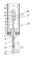
- the present invention will be described in further detail using examples and with reference to the attached drawing, which shows a reactor or treatment vessel or container 20 for the treatment of molten mass, involving the use of a rotor 9.
- the reactor jacket 19 itself may expediently be produced from a suitable steel material.
- the steel jacket 19 is lined on the inside with fireproof material 1.
- a moulded brick 2 is embedded in the reactor's base lining 1.
- a stator pipe 3 with a seal 4, which forms a seal between the moulded brick 2 and the stator pipe 3, is inserted from the bottom of the reactor.
- the stator pipe 3 is made of a fireproof, insulating material which is resistant to the molten mass and has a given thermal conductivity.
- the stator pipe is guided vertically and horizontally by a collar 5 which is made of an insulating material.
- the collar is located on a steel flange 6 which is bolted to the bottom of the reactor jacket. This creates a prestress on the seal 4 which is located between the stator pipe 3 and moulded brick 2. This prestress is important for the absorption of differences in thermal expansion and shrinkage between the various materials.
- the bearing support 7 for the rotor shaft 8 is mounted against the steel flange 6. The bearings are cooled using forced air cooling.
- the drive shaft 8 of the rotor 9 is inserted down into the stator pipe from the top and ends in a quick-action coupling 10 in the bearing support.
- a belt pulley 11 driven via an electric motor 12 is located above the quick-action coupling.
- the rotor 9 is of the same type as that shown and described in the applicant's own European patent no. 0151434, which is hollow inside and has an opening 21 at the bottom end and holes 18 in the sides.
- the rotor is fixed to the drive shaft at the top, expediently via, for example, a thread connection or a carrier arrangement in the form of a cotter or bolt connection.
- the stator pipe 3 extends from the base of the reactor through the hole in the base of the rotor 9 and into the cavity in the rotor with a certain clearance to the internal top surface 14 of the rotor.
- Gas and/or particulate material for the treatment of the liquid may expediently be supplied through a drilled hole in the rotor shaft (not shown in further detail) or through the annulus between the shaft and the stator pipe.
- gas may be supplied via a drilled hole in the shaft and any surplus gas may be returned through the stated annulus.
- the reactor may also be fitted with a lid (not shown in further detail) so that the molten mass may be treated in a closed system, for example under an inert atmosphere.
- the invention as it is defined in the claims is not restricted to the embodiment shown in the figure or described above.
- the rotor with the embodiment shown may be used to treat liquids other than molten metal, for example suspensions such as sewage or other types of contaminated water.
Landscapes
- Chemical & Material Sciences (AREA)
- Engineering & Computer Science (AREA)
- Chemical Kinetics & Catalysis (AREA)
- Organic Chemistry (AREA)
- Mechanical Engineering (AREA)
- Metallurgy (AREA)
- Materials Engineering (AREA)
- Manufacturing & Machinery (AREA)
- Manufacture And Refinement Of Metals (AREA)
- Treatment Of Steel In Its Molten State (AREA)
- Physical Or Chemical Processes And Apparatus (AREA)
- Mixers Of The Rotary Stirring Type (AREA)
- Vaporization, Distillation, Condensation, Sublimation, And Cold Traps (AREA)
- Waste-Gas Treatment And Other Accessory Devices For Furnaces (AREA)
Abstract
Description
Hence, the rotor with the embodiment shown may be used to treat liquids other than molten metal, for example suspensions such as sewage or other types of contaminated water.
Still another major advantage of the use of a stator pipe which ends in an air pocket in the rotor is that there is no need for expensive seals which would otherwise be necessary if the shaft had extended through the base without the stator pipe.
Claims (4)
- A device in connection with a rotor (9) for the treatment of a liquid such as molten metal in a reactor (20) or similar by supplying gas and/or particulate material to the liquid, preferably via the rotor shaft (8) and through openings (18) from a cavity (16) in the rotor,
characterised in that
the rotor shaft (8) extends up through the base of the reactor (20) and is arranged so that it may rotate inside a stator pipe (3) which extends up from the base of the reactor, whereby the rotor shaft and the stator pipe extend through an opening (21) in the lower side of the rotor (9) and into the cavity (16) of the rotor and whereby the rotor shaft (8) is connected to the rotor (9) via a fixing device (13) inside the rotor cavity, while the stator pipe (3) ends in the cavity (16). - A device in accordance with claim 1,
characterised in that
the shaft (8) is directly connected to the rotor (9) by means of a thread connection, cotter or bolt connection. - A device in accordance with claim 1,
characterised in that
gas and/or particulate material is supplied to the cavity (16) in the rotor via a drilled hole in the shaft (8) or via the annulus between the shaft (8) and the stator pipe (3). - A device in accordance with claims 1 and 3,
characterised in that
any surplus gas is designed to be returned via the annulus between the shaft (8) and the stator pipe (3).
Applications Claiming Priority (2)
| Application Number | Priority Date | Filing Date | Title |
|---|---|---|---|
| NO20000974A NO311228B1 (en) | 2000-02-25 | 2000-02-25 | Device by rotor for treating a liquid such as metal melt |
| NO20000974 | 2000-02-25 |
Publications (3)
| Publication Number | Publication Date |
|---|---|
| EP1127610A2 true EP1127610A2 (en) | 2001-08-29 |
| EP1127610A3 EP1127610A3 (en) | 2001-12-19 |
| EP1127610B1 EP1127610B1 (en) | 2006-05-31 |
Family
ID=19910793
Family Applications (1)
| Application Number | Title | Priority Date | Filing Date |
|---|---|---|---|
| EP01103791A Expired - Lifetime EP1127610B1 (en) | 2000-02-25 | 2001-02-16 | Rotor for the treatment of a liquid such as a metal melt |
Country Status (11)
| Country | Link |
|---|---|
| US (1) | US6471912B2 (en) |
| EP (1) | EP1127610B1 (en) |
| JP (1) | JP5041622B2 (en) |
| AU (1) | AU778666B2 (en) |
| CA (1) | CA2338110C (en) |
| DE (1) | DE60120004T2 (en) |
| NO (1) | NO311228B1 (en) |
| NZ (1) | NZ510051A (en) |
| PL (1) | PL196480B1 (en) |
| SI (1) | SI20463B (en) |
| SK (1) | SK285980B6 (en) |
Cited By (1)
| Publication number | Priority date | Publication date | Assignee | Title |
|---|---|---|---|---|
| WO2003074163A1 (en) * | 2002-03-04 | 2003-09-12 | Cymat Corp. | Sealed impeller for producing metal foam and system and method therefor |
Families Citing this family (1)
| Publication number | Priority date | Publication date | Assignee | Title |
|---|---|---|---|---|
| CN113088933A (en) * | 2020-12-14 | 2021-07-09 | 芯三代半导体科技(苏州)有限公司 | Rotating device |
Family Cites Families (10)
| Publication number | Priority date | Publication date | Assignee | Title |
|---|---|---|---|---|
| US2767965A (en) * | 1950-11-03 | 1956-10-23 | Mining Process & Patent Co | Dual pumping agitation |
| US2875897A (en) * | 1953-06-22 | 1959-03-03 | Booth Lionel Earl | Flotation machine |
| US2890039A (en) * | 1953-11-02 | 1959-06-09 | Karl Schmidt Metallschmelzwerk | Apparatus for the introduction of substances into liquids of high specific gravity |
| US4002323A (en) * | 1975-08-07 | 1977-01-11 | Luco-Technic Ag | Arrangement for mixing and treating powdered and granular material |
| JPS55106532A (en) * | 1979-02-13 | 1980-08-15 | Babcock Hitachi Kk | Contacting device for gas and liquid |
| JPS5829127B2 (en) * | 1980-03-25 | 1983-06-21 | 日本産業技術株式会社 | Device that generates ultrafine bubbles in liquid |
| JPS5720932U (en) * | 1980-07-09 | 1982-02-03 | ||
| JPS5826927U (en) * | 1981-08-19 | 1983-02-21 | 石川島播磨重工業株式会社 | Gas blowing device into liquid phase |
| NO155447C (en) * | 1984-01-25 | 1987-04-01 | Ardal Og Sunndal Verk | DEVICE FOR PLANT FOR TREATMENT OF A FLUID, E.g. AN ALUMINUM MELT. |
| DE8809812U1 (en) * | 1988-08-02 | 1988-09-22 | A. Stephan u. Söhne GmbH & Co, 31789 Hameln | Food processing machine |
-
2000
- 2000-02-25 NO NO20000974A patent/NO311228B1/en not_active IP Right Cessation
-
2001
- 2001-02-16 EP EP01103791A patent/EP1127610B1/en not_active Expired - Lifetime
- 2001-02-16 DE DE60120004T patent/DE60120004T2/en not_active Expired - Lifetime
- 2001-02-20 NZ NZ510051A patent/NZ510051A/en not_active IP Right Cessation
- 2001-02-20 AU AU23115/01A patent/AU778666B2/en not_active Expired
- 2001-02-22 US US09/789,815 patent/US6471912B2/en not_active Expired - Lifetime
- 2001-02-22 SK SK255-2001A patent/SK285980B6/en not_active IP Right Cessation
- 2001-02-23 CA CA002338110A patent/CA2338110C/en not_active Expired - Lifetime
- 2001-02-23 PL PL346086A patent/PL196480B1/en unknown
- 2001-02-23 SI SI200100049A patent/SI20463B/en active Search and Examination
- 2001-02-26 JP JP2001050699A patent/JP5041622B2/en not_active Expired - Lifetime
Cited By (2)
| Publication number | Priority date | Publication date | Assignee | Title |
|---|---|---|---|---|
| WO2003074163A1 (en) * | 2002-03-04 | 2003-09-12 | Cymat Corp. | Sealed impeller for producing metal foam and system and method therefor |
| US7481964B2 (en) | 2002-03-04 | 2009-01-27 | Cymat Corp. | Sealed impeller for producing metal foam and system and method therefor |
Also Published As
| Publication number | Publication date |
|---|---|
| NO311228B1 (en) | 2001-10-29 |
| JP5041622B2 (en) | 2012-10-03 |
| PL346086A1 (en) | 2001-08-27 |
| AU2311501A (en) | 2001-08-30 |
| SK285980B6 (en) | 2007-12-06 |
| NO20000974L (en) | 2001-08-27 |
| SI20463B (en) | 2010-05-31 |
| SI20463A (en) | 2001-08-31 |
| US6471912B2 (en) | 2002-10-29 |
| US20010017434A1 (en) | 2001-08-30 |
| EP1127610A3 (en) | 2001-12-19 |
| NZ510051A (en) | 2001-09-28 |
| CA2338110A1 (en) | 2001-08-25 |
| DE60120004D1 (en) | 2006-07-06 |
| AU778666B2 (en) | 2004-12-16 |
| JP2001262244A (en) | 2001-09-26 |
| DE60120004T2 (en) | 2007-05-10 |
| EP1127610B1 (en) | 2006-05-31 |
| PL196480B1 (en) | 2008-01-31 |
| SK2552001A3 (en) | 2001-10-08 |
| CA2338110C (en) | 2009-08-25 |
| NO20000974D0 (en) | 2000-02-25 |
Similar Documents
| Publication | Publication Date | Title |
|---|---|---|
| US12163536B2 (en) | Quick submergence molten metal pump | |
| US6123523A (en) | Gas-dispersion device | |
| US5676520A (en) | Method and apparatus for inhibiting oxidation in pumps for pumping molten metal | |
| US5718416A (en) | Lid and containment vessel for refining molten metal | |
| US20170037852A1 (en) | Overflow vortex transfer system | |
| JP5217828B2 (en) | Molten metal cleaning equipment | |
| US20080230966A1 (en) | Scrap melter and impeller therefore | |
| AU697641B2 (en) | Apparatus for treating liquids | |
| HU183077B (en) | Apparatus for refining melted metals | |
| US6056803A (en) | Injector for gas treatment of molten metals | |
| EP1127610B1 (en) | Rotor for the treatment of a liquid such as a metal melt | |
| EP0919111A1 (en) | Method and apparatus for removing a molten material with a vacuum from a chamber | |
| EP1480735B1 (en) | Sealed impeller for producing metal foam and system | |
| RU2244021C2 (en) | Device for treatment of liquid metal | |
| US4456230A (en) | Apparatus for the separation of metallic zinc from residues containing zinc | |
| CA2807009C (en) | Pump for pumping molten metal including components that resist deterioration | |
| CN2328671Y (en) | Aluminium all9y deaerator of suspending rotary blowing rotor | |
| SU933733A1 (en) | Vaccuum treatment apparatus | |
| SU1319911A1 (en) | Aeration assembly of flotation machine | |
| JPH0320446B2 (en) | ||
| CN1650116A (en) | Hydraulic motor for use in high-pressure environment | |
| JPH0458596B2 (en) |
Legal Events
| Date | Code | Title | Description |
|---|---|---|---|
| PUAI | Public reference made under article 153(3) epc to a published international application that has entered the european phase |
Free format text: ORIGINAL CODE: 0009012 |
|
| AK | Designated contracting states |
Kind code of ref document: A2 Designated state(s): CH DE FR GB LI SE Kind code of ref document: A2 Designated state(s): AT BE CH CY DE DK ES FI FR GB GR IE IT LI LU MC NL PT SE TR |
|
| AX | Request for extension of the european patent |
Free format text: AL;LT;LV;MK;RO;SI |
|
| PUAL | Search report despatched |
Free format text: ORIGINAL CODE: 0009013 |
|
| AK | Designated contracting states |
Kind code of ref document: A3 Designated state(s): AT BE CH CY DE DK ES FI FR GB GR IE IT LI LU MC NL PT SE TR |
|
| AX | Request for extension of the european patent |
Free format text: AL;LT;LV;MK;RO;SI |
|
| 17P | Request for examination filed |
Effective date: 20020619 |
|
| AKX | Designation fees paid |
Free format text: CH DE FR GB LI SE |
|
| 17Q | First examination report despatched |
Effective date: 20031016 |
|
| GRAP | Despatch of communication of intention to grant a patent |
Free format text: ORIGINAL CODE: EPIDOSNIGR1 |
|
| GRAS | Grant fee paid |
Free format text: ORIGINAL CODE: EPIDOSNIGR3 |
|
| GRAA | (expected) grant |
Free format text: ORIGINAL CODE: 0009210 |
|
| AK | Designated contracting states |
Kind code of ref document: B1 Designated state(s): CH DE FR GB LI SE |
|
| REG | Reference to a national code |
Ref country code: GB Ref legal event code: FG4D Ref country code: CH Ref legal event code: EP |
|
| REF | Corresponds to: |
Ref document number: 60120004 Country of ref document: DE Date of ref document: 20060706 Kind code of ref document: P |
|
| REG | Reference to a national code |
Ref country code: CH Ref legal event code: NV Representative=s name: E. BLUM & CO. PATENTANWAELTE |
|
| REG | Reference to a national code |
Ref country code: SE Ref legal event code: TRGR |
|
| ET | Fr: translation filed | ||
| PLBE | No opposition filed within time limit |
Free format text: ORIGINAL CODE: 0009261 |
|
| STAA | Information on the status of an ep patent application or granted ep patent |
Free format text: STATUS: NO OPPOSITION FILED WITHIN TIME LIMIT |
|
| 26N | No opposition filed |
Effective date: 20070301 |
|
| REG | Reference to a national code |
Ref country code: CH Ref legal event code: PFA Owner name: NORSK HYDRO ASA Free format text: NORSK HYDRO ASA# #0240 OSLO (NO) -TRANSFER TO- NORSK HYDRO ASA# #0240 OSLO (NO) |
|
| REG | Reference to a national code |
Ref country code: DE Ref legal event code: R082 Ref document number: 60120004 Country of ref document: DE Representative=s name: KOTITSCHKE & HEURUNG PARTNERSCHAFT MBB PATENT-, DE Ref country code: DE Ref legal event code: R082 Ref document number: 60120004 Country of ref document: DE Representative=s name: DR. RALF KOTITSCHKE, DE |
|
| REG | Reference to a national code |
Ref country code: FR Ref legal event code: PLFP Year of fee payment: 16 |
|
| REG | Reference to a national code |
Ref country code: FR Ref legal event code: PLFP Year of fee payment: 17 |
|
| REG | Reference to a national code |
Ref country code: FR Ref legal event code: PLFP Year of fee payment: 18 |
|
| PGFP | Annual fee paid to national office [announced via postgrant information from national office to epo] |
Ref country code: SE Payment date: 20200220 Year of fee payment: 20 Ref country code: DE Payment date: 20200219 Year of fee payment: 20 Ref country code: GB Payment date: 20200219 Year of fee payment: 20 |
|
| PGFP | Annual fee paid to national office [announced via postgrant information from national office to epo] |
Ref country code: CH Payment date: 20200219 Year of fee payment: 20 |
|
| PGFP | Annual fee paid to national office [announced via postgrant information from national office to epo] |
Ref country code: FR Payment date: 20200219 Year of fee payment: 20 |
|
| REG | Reference to a national code |
Ref country code: DE Ref legal event code: R071 Ref document number: 60120004 Country of ref document: DE |
|
| REG | Reference to a national code |
Ref country code: CH Ref legal event code: PL |
|
| REG | Reference to a national code |
Ref country code: GB Ref legal event code: PE20 Expiry date: 20210215 |
|
| REG | Reference to a national code |
Ref country code: SE Ref legal event code: EUG |
|
| PG25 | Lapsed in a contracting state [announced via postgrant information from national office to epo] |
Ref country code: GB Free format text: LAPSE BECAUSE OF EXPIRATION OF PROTECTION Effective date: 20210215 |