EP1127586A2 - Ocular iontophoretic apparatus handle - Google Patents
Ocular iontophoretic apparatus handle Download PDFInfo
- Publication number
- EP1127586A2 EP1127586A2 EP01101307A EP01101307A EP1127586A2 EP 1127586 A2 EP1127586 A2 EP 1127586A2 EP 01101307 A EP01101307 A EP 01101307A EP 01101307 A EP01101307 A EP 01101307A EP 1127586 A2 EP1127586 A2 EP 1127586A2
- Authority
- EP
- European Patent Office
- Prior art keywords
- handle
- region
- housing member
- regions
- flexing
- Prior art date
- Legal status (The legal status is an assumption and is not a legal conclusion. Google has not performed a legal analysis and makes no representation as to the accuracy of the status listed.)
- Granted
Links
Images


Classifications
-
- A—HUMAN NECESSITIES
- A61—MEDICAL OR VETERINARY SCIENCE; HYGIENE
- A61N—ELECTROTHERAPY; MAGNETOTHERAPY; RADIATION THERAPY; ULTRASOUND THERAPY
- A61N1/00—Electrotherapy; Circuits therefor
- A61N1/18—Applying electric currents by contact electrodes
- A61N1/20—Applying electric currents by contact electrodes continuous direct currents
- A61N1/30—Apparatus for iontophoresis, i.e. transfer of media in ionic state by an electromotoric force into the body, or cataphoresis
- A61N1/303—Constructional details
Definitions
- the present invention is directed to ocular iontophoretic apparatuses, and more particularly, to a handle for an ocular iontophoretic apparatus to facilitate the grasping, positioning and placement thereof.
- ocular iontophoretic devices have been known in the art. Such devices have been used in an attempt to administer a drug through an electromotive force which drives ionic chemicals through the eye tissue so that they can be absorbed by adjacent tissues and blood vessels.
- the application comprises an iontophoretic apparatus which includes a housing member, a current distribution member, a medicament containment member and a handle member.
- the current distribution member is associated with the housing member.
- the medicament containment member is associated with the current distribution member.
- the handle member is associated with the housing member, and the handle member serves to facilitate the positioning and/or placement of the iontophoretic apparatus.
- the handle member comprises a first handle region and a second handle region extending outwardly from the handle member.
- Each of the first and second handle regions are preferably co-molded with the housing member and distally spaced apart a predetermined distance.
- the first and second handle regions extend away from each other.
- the handle member may be releasably associated with the housing member.
- At least one of the first and second handle regions includes a gripping region.
- the gripping region facilitates the overall gripping of the handle region by a user during the positioning and/or placement of the apparatus.
- the first and second handle regions include a grasping region which joins the handle regions together to, in turn, render a single unitary handle region.
- first and second handle regions include means for flexing the housing member.
- first and second handle regions further include means for limiting the flexing of the housing member.
- the flexing limiting means may comprise the positioning of a portion of the first and second handle regions in a spaced apart orientation. The spaced apart orientation substantially corresponds to the desired maximum flex of the housing member.
- the flexing limiting means further includes means for aligning the first and second handle regions.
- the aligning means precludes inadvertent misalignment of the first and second handle regions during flexing.
- the apparatus further includes means for maintaining the registered placement of the apparatus in the desired orientation.
- the registered placement maintaining means may comprise a receiving region associated with one or both of the handle member and the housing member.
- the receiving region comprises at least one notch.
- the apparatus may further include means for biasing at least a portion of the receiving region against the soft tissue of a user.
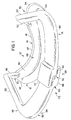
- Iontophoretic apparatus 10 is shown in Figs. 1 and 2 as comprising housing member 12, current distribution member 14, medicament containment member 16 and handle member 18.
- the housing member, the current distribution member and the medicament containment member are each described in detail in co-pending application serial number 09/318,181 entitled “Methods and Apparatus for Ocular Iontophoresis," the complete specification of which is incorporated herein by reference.
- the housing member includes outer surface 40, first end 42, second end 44, upper region 45 and rim 47.
- the housing comprises a plastic material which is molded into a desired configuration for the positioning thereof on the eye of a patient.
- housing member 12 may be of any number of sizes and shapes. Various embodiments of the housing member may include various configurations depending on the medicament to be dispensed, as well as the specific shape of the soft tissue surrounding the eye of the patient, and the particular region of the eye to which it is to be applied. Of course, the handle member is not limited to any particular housing member configurations and may be used with a wide variety of such devices. Additionally, the medicament that is retained in medicament containment member 16 for dispensing is not limited to any particular medicament, and virtually any medicament that can be applied iontophoretically through the eye can be used in association with the iontophoretic apparatus.
- Handle member 18 is shown primarily in Figs. 1 and 5 as comprising first handle region 20, second handle region 22, means 24 for flexing the handle member, means 26 for limiting the flexing of the handle member and means 25 for maintaining registered placement of the apparatus.
- handle member 18 is co-molded with housing member 12, however, it is likewise contemplated that the handle member may comprise a separate component which may be welded, adhered or otherwise joined to housing member 12.
- the handle member is generally associated with the upper region 45, which, in turn, facilitates placement of the device along, for example, the lower edge of the patient's eye under the lower eyelid. In addition, such handle positioning minimizes the intrusiveness of the handle member and the discomfort to the patient receiving treatment, while maximizing the versatility thereof.
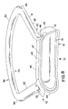
- First handle region 20 of the handle member is shown in Figs. 3 and 4 as including first end 46, second end 48 and first gripping portion 50.
- First end 46 is associated with outer surface 40 proximate first end 42 of the housing member.
- Second end 48 extends outwardly therefrom and in a direction which is generally away from second handle region 22 of the handle member.
- First gripping portion 50 is positioned proximate second end 48 of first handle region 20.
- first gripping portion 50 comprises a region which is sized and shaped so as to promote the gripping thereof by a doctor or other professional during placement of the iontophoretic apparatus in the eye of a patient. As can be seen in Figs.
- first gripping portion 50 is substantially planar and spaced apart from the housing member a distance sufficient to insure that the doctor can easily grip the gripping portion without inadvertently striking or touching the patient.
- the gripping region comprises a substantially flat pod region 51 (Fig. 7).
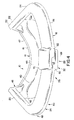
- second handle region 22 is substantially similar to first handle region 20, and comprises first end 52, second end 54 and second gripping portion 56. While various configurations are contemplated, generally, the first and second handle regions are substantial mirror images of each other (and are substantially symmetrical) about central axis 101 (Fig. 2) of the housing member.
- gripping portion 50 of first handle region 20 and gripping portion 56 of second handle region 22 are integrally associated with each other, to, in turn, define a single loop like configuration for the gripping portion.
- the integrated gripping portion extends from second end 48 of first handle region 20 to second end 54 of second handle region 22.
- the integrated gripping portion is substantially parallel to the housing member and generally follows the surface configuration of the outer surface 40 of housing member 12.
- handle member 18 may be removably associated with housing member 12.
- handle member 18 includes means 74 for releasably retaining the handle member to the housing member.
- Releasable retaining means 74 includes hoop 76 which is releasably positionable within grooved recess 78 of the housing member.
- the handle member can be removed by pulling thereon, to, in turn, release hoop 76 from within recess 78 of the housing member.
- the removable handle member is shown as including a single gripping region, other handle members, including, but not limited to, those shown in Figs. 1, 7 and 8 are likewise contemplated.
- gripping portion 50 of first handle region 20 and gripping portion 56 of second handle region 22 are spaced apart a predetermined distance from each other, to essentially provide a means for flexing the housing.
- the force in turn, flexes the housing member.
- Placement of a gap between the first and second gripping portions defines means 26 for limiting the flexing of the housing member.
- gripping portion 50 and gripping portion 56 extend from the respective second ends of the respective handle regions so as to be substantially parallel to outer surface 40 of housing member 12.
- the two gripping portions essentially extend toward each other until end 62 of first gripping portion 50 is separated from end 64 of second gripping portion 56 by a gap.
- the distance separating the two gripping portions becomes smaller until end 62 of first gripping portion is in abutment with end 64 of second gripping portion 56.
- the respective gripping portions can be pinched no further and additional flexing of the housing member is not possible.
- the flexing limiting means further includes means 32 for aligning the respective ends of the gripping portions.
- aligning means 32 includes first alignment member 68 which is associated with end 60 of gripping portion 50 and second alignment member 70 which is associated with end 62 of gripping portion 52.
- first alignment member 68 which is associated with end 60 of gripping portion 50
- second alignment member 70 which is associated with end 62 of gripping portion 52.
- the alignment members insure that end 60 of gripping portion 50 is aligned with end 62 of gripping portion 52, so that the flexing can be limited by the interaction and abutment of the two ends. Indeed, without the alignment members, inadvertent misalignment of the ends would permit the flexing of the respective ends without limitation and beyond that which is desirable.
- Placement registration means 25 is shown in Fig. 1 as including retaining regions 70, 72 and means 73 for biasing the retaining region against the soft tissue of a patient.
- Retaining region 70 is associated with one or both of first end 46 of first handle region 20 and first end 42 of housing member 12.
- retaining region 72 is associated with one or both of first end 52 of second handle region 22 and second end 44 of housing member 12.
- the retaining regions comprise structures, such as notches that are configured to cooperate with the corner area of the soft tissue surrounding the eye of the user.
- Biasing means 73 comprises the natural resilience of the material surrounding retaining region 70 to return to its original configuration upon flexing thereby biasing the retaining regions against the soft tissue of a patient.
- the corner areas of the eye, the retaining regions and the biasing means cooperate to maintain the registered placement of the apparatus in the desired orientation, and substantially preclude movement of the apparatus once positioned. It is also contemplated that the placement registration means is not limited to cooperation with the comers of the eyes; rather, it can also cooperate with other surrounding tissues that remain substantially static during movement of the eye.
- the electrical leads which attach the power supply to the electrodes which drive the medicament may be molded into the handle member.
- the doctor, physician's assistant or other professional first selects the appropriate apparatus from among various apparatuses of different size, shape and medicament.
- the apparatus is not limited to any particular shape and any particular medicament.
- the doctor first pinches the respective gripping portions 50, 56 toward each other so as to flex housing member 12.
- the user positions the housing member on the surface of the patient's eye.
- the doctor slowly releases the pinching grip on the gripping regions, and housing member 12 returns to its original orientation at which time the entire outer rim 46 is in contact with the surface of the eye.
- the corner regions of the eye are positioned into and accepted by retaining regions 70 and 72 of registered placement maintaining means 25 so as to achieve registered placement of the apparatus in the desired orientation.
- biasing means 73 of registered placement maintaining means 25 cooperates with the retaining regions to bias and, in turn, maintain the corner of the eye and the retaining regions in cooperative engagement.
- the cooperation of the registered placement maintaining means and the biasing means can also compensate for size variation in the dimensions of the soft tissue surrounding the eye.
- biasing means 73 and the flexing means of the handle member may be integrated into a single structure.
- the doctor initiates current delivery from the current distribution member.
- the current forces medicament retained in the medicament containment member through the tissue of the patient's eye.
- the treatment continues for a predetermined period of time which is determined by the type and quantity of medicament that is to be transmitted to the patient.
- the apparatus can be removed from the patient. Specifically, the doctor again grasps the gripping regions of handle member 12 and pulls the housing from the surface of the eye.
- the user pinches gripping portions 50 and 56 until housing member 12 flexes.
- the flexing of the housing member likewise facilitates the release of the housing member from the surface of the eye in a controlled manner.
- the user may individually grasp each of the separate gripping members to release the housing member from the surface of the eye.
- the doctor can grab the unitized gripping member to release the housing member from the surface of the eye.
Abstract
Description
- The present invention is directed to ocular iontophoretic apparatuses, and more particularly, to a handle for an ocular iontophoretic apparatus to facilitate the grasping, positioning and placement thereof.
- The use of ocular iontophoretic devices has been known in the art. Such devices have been used in an attempt to administer a drug through an electromotive force which drives ionic chemicals through the eye tissue so that they can be absorbed by adjacent tissues and blood vessels.
- Among other problems, difficulties can be incurred with the placement of these devices onto the surface of the eye of a patient. Specifically, inasmuch as certain of these devices are intended for use on only a portion of the eye, they are rather small in size. Accordingly, it is difficult for a doctor to carefully position the device in the proper orientation. Moreover, once placed on the patient's eye, it is often difficult to reposition or to adjust the positioning of the device.
- Accordingly, it is an object of the invention to provide for a handle member which facilitates the grasping, positioning and placement of ocular iontophoretic apparatuses.
- It is likewise an object of the invention to facilitate the repositioning of an ocular iontophoretic apparatus after placement onto the surface of the eye.
- It is a further object of the invention to provide for a handle member which can be pinched so as to flex the iontophoretic apparatus during placement onto an eye and during removal from the eye of the patient.
- These and other objects of the invention will become apparent in light of the specification and claims appended hereto.
- The application comprises an iontophoretic apparatus which includes a housing member, a current distribution member, a medicament containment member and a handle member. The current distribution member is associated with the housing member. The medicament containment member is associated with the current distribution member. The handle member is associated with the housing member, and the handle member serves to facilitate the positioning and/or placement of the iontophoretic apparatus.
- In a preferred embodiment, the handle member comprises a first handle region and a second handle region extending outwardly from the handle member. Each of the first and second handle regions are preferably co-molded with the housing member and distally spaced apart a predetermined distance. In one such embodiment, the first and second handle regions extend away from each other. In another embodiment, the handle member may be releasably associated with the housing member.
- In another preferred embodiment, at least one of the first and second handle regions includes a gripping region. The gripping region facilitates the overall gripping of the handle region by a user during the positioning and/or placement of the apparatus. In another such embodiment, the first and second handle regions include a grasping region which joins the handle regions together to, in turn, render a single unitary handle region.
- In another preferred embodiment, the first and second handle regions include means for flexing the housing member. In one such embodiment, the first and second handle regions further include means for limiting the flexing of the housing member. In one embodiment, the flexing limiting means may comprise the positioning of a portion of the first and second handle regions in a spaced apart orientation. The spaced apart orientation substantially corresponds to the desired maximum flex of the housing member.
- In another such embodiment, the flexing limiting means further includes means for aligning the first and second handle regions. The aligning means precludes inadvertent misalignment of the first and second handle regions during flexing.
- In another preferred embodiment, the apparatus further includes means for maintaining the registered placement of the apparatus in the desired orientation. In one such embodiment, the registered placement maintaining means may comprise a receiving region associated with one or both of the handle member and the housing member. In one such embodiment, the receiving region comprises at least one notch. Preferably, the apparatus may further include means for biasing at least a portion of the receiving region against the soft tissue of a user.
-
- Fig. 1 of the drawings is a perspective view of the first embodiment of the apparatus of the present invention;
- Fig. 2 of the drawings is a perspective view of the first embodiment of the apparatus of the present invention;
- Fig. 3 of the drawings is a perspective view of the first embodiment of the apparatus of the present invention;
- Fig. 4 of the drawings is a perspective view of the first embodiment of the apparatus of the present invention;
- Fig. 5 of the drawings is a perspective view of the first embodiment of the apparatus of the present invention;
- Fig. 6 of the drawings is a perspective view of the first embodiment of the apparatus of the present invention;
- Fig. 7 of the drawings is a perspective view of a second embodiment of the apparatus of the present invention;
- Fig. 8 of the drawings is a perspective view of a third embodiment of the apparatus of the present invention;
- Fig. 9 of the drawings is a perspective view of a fourth embodiment of the apparatus of the present invention; and
- Fig. 10 of the drawings is a perspective view of the fourth embodiment of the apparatus of the present invention.
-
- While this invention is susceptible of embodiment in many different forms, there is shown in the drawings and will be described in detail, several specific embodiments with the understanding that the present disclosure is to be considered as an exemplification of the principles of the invention and is not intended to limit the invention to the embodiments illustrated.
-
Iontophoretic apparatus 10 is shown in Figs. 1 and 2 as comprisinghousing member 12,current distribution member 14,medicament containment member 16 andhandle member 18. The housing member, the current distribution member and the medicament containment member are each described in detail in co-pending application serial number 09/318,181 entitled "Methods and Apparatus for Ocular Iontophoresis," the complete specification of which is incorporated herein by reference. As described therein in greater detail, the housing member includesouter surface 40,first end 42,second end 44,upper region 45 andrim 47. Generally, the housing comprises a plastic material which is molded into a desired configuration for the positioning thereof on the eye of a patient. - As will be understood,
housing member 12 may be of any number of sizes and shapes. Various embodiments of the housing member may include various configurations depending on the medicament to be dispensed, as well as the specific shape of the soft tissue surrounding the eye of the patient, and the particular region of the eye to which it is to be applied. Of course, the handle member is not limited to any particular housing member configurations and may be used with a wide variety of such devices. Additionally, the medicament that is retained inmedicament containment member 16 for dispensing is not limited to any particular medicament, and virtually any medicament that can be applied iontophoretically through the eye can be used in association with the iontophoretic apparatus. -
Handle member 18 is shown primarily in Figs. 1 and 5 as comprisingfirst handle region 20,second handle region 22, means 24 for flexing the handle member, means 26 for limiting the flexing of the handle member and means 25 for maintaining registered placement of the apparatus. Generally,handle member 18 is co-molded withhousing member 12, however, it is likewise contemplated that the handle member may comprise a separate component which may be welded, adhered or otherwise joined tohousing member 12. In addition, the handle member is generally associated with theupper region 45, which, in turn, facilitates placement of the device along, for example, the lower edge of the patient's eye under the lower eyelid. In addition, such handle positioning minimizes the intrusiveness of the handle member and the discomfort to the patient receiving treatment, while maximizing the versatility thereof. -
First handle region 20 of the handle member is shown in Figs. 3 and 4 as includingfirst end 46,second end 48 andfirst gripping portion 50.First end 46 is associated withouter surface 40 proximatefirst end 42 of the housing member.Second end 48 extends outwardly therefrom and in a direction which is generally away fromsecond handle region 22 of the handle member. First grippingportion 50 is positioned proximatesecond end 48 offirst handle region 20. Generally, first grippingportion 50 comprises a region which is sized and shaped so as to promote the gripping thereof by a doctor or other professional during placement of the iontophoretic apparatus in the eye of a patient. As can be seen in Figs. 5 and 6, first grippingportion 50 is substantially planar and spaced apart from the housing member a distance sufficient to insure that the doctor can easily grip the gripping portion without inadvertently striking or touching the patient. In certain embodiments the gripping region comprises a substantially flat pod region 51 (Fig. 7). - It will be understood that
second handle region 22 is substantially similar tofirst handle region 20, and comprisesfirst end 52,second end 54 and second grippingportion 56. While various configurations are contemplated, generally, the first and second handle regions are substantial mirror images of each other (and are substantially symmetrical) about central axis 101 (Fig. 2) of the housing member. - In the embodiment shown in Fig. 8, gripping
portion 50 offirst handle region 20 and grippingportion 56 ofsecond handle region 22 are integrally associated with each other, to, in turn, define a single loop like configuration for the gripping portion. In such an embodiment, the integrated gripping portion extends fromsecond end 48 offirst handle region 20 tosecond end 54 ofsecond handle region 22. The integrated gripping portion is substantially parallel to the housing member and generally follows the surface configuration of theouter surface 40 ofhousing member 12. - In the embodiment shown in Figs. 9 and 10,
handle member 18 may be removably associated withhousing member 12. Specifically, in such an embodiment, handlemember 18 includesmeans 74 for releasably retaining the handle member to the housing member. Releasable retaining means 74 includeshoop 76 which is releasably positionable within groovedrecess 78 of the housing member. As will be understood, once the apparatus is positioned as desired in the eye, the handle member can be removed by pulling thereon, to, in turn,release hoop 76 from withinrecess 78 of the housing member. Additionally, it will be understood that while the removable handle member is shown as including a single gripping region, other handle members, including, but not limited to, those shown in Figs. 1, 7 and 8 are likewise contemplated. - In the embodiment shown in Figs. 5 and 6, gripping
portion 50 offirst handle region 20 and grippingportion 56 ofsecond handle region 22 are spaced apart a predetermined distance from each other, to essentially provide a means for flexing the housing. Specifically, and as will be explained in more detail below with respect to the operation, as the doctor or professional pinches the first and secondgripping portions handle regions - Placement of a gap between the first and second gripping portions defines means 26 for limiting the flexing of the housing member. Specifically, gripping
portion 50 and grippingportion 56 extend from the respective second ends of the respective handle regions so as to be substantially parallel toouter surface 40 ofhousing member 12. The two gripping portions essentially extend toward each other untilend 62 of first grippingportion 50 is separated from end 64 of second grippingportion 56 by a gap. Thus, as the user pinches the gripping members, the distance separating the two gripping portions becomes smaller untilend 62 of first gripping portion is in abutment with end 64 of second grippingportion 56. At such time, the respective gripping portions can be pinched no further and additional flexing of the housing member is not possible. - As shown in Figs. 5 and 6, the flexing limiting means further includes
means 32 for aligning the respective ends of the gripping portions. In particular, aligningmeans 32 includesfirst alignment member 68 which is associated withend 60 of grippingportion 50 andsecond alignment member 70 which is associated withend 62 of grippingportion 52. As will be understood, as the user flexes the ends, the alignment members insure thatend 60 of grippingportion 50 is aligned withend 62 of grippingportion 52, so that the flexing can be limited by the interaction and abutment of the two ends. Indeed, without the alignment members, inadvertent misalignment of the ends would permit the flexing of the respective ends without limitation and beyond that which is desirable. - Placement registration means 25 is shown in Fig. 1 as including retaining
regions region 70 is associated with one or both offirst end 46 offirst handle region 20 andfirst end 42 ofhousing member 12. Similarly, retainingregion 72 is associated with one or both offirst end 52 ofsecond handle region 22 andsecond end 44 ofhousing member 12. The retaining regions comprise structures, such as notches that are configured to cooperate with the corner area of the soft tissue surrounding the eye of the user. Biasing means 73 comprises the natural resilience of the material surrounding retainingregion 70 to return to its original configuration upon flexing thereby biasing the retaining regions against the soft tissue of a patient. As will be explained, the corner areas of the eye, the retaining regions and the biasing means cooperate to maintain the registered placement of the apparatus in the desired orientation, and substantially preclude movement of the apparatus once positioned. It is also contemplated that the placement registration means is not limited to cooperation with the comers of the eyes; rather, it can also cooperate with other surrounding tissues that remain substantially static during movement of the eye. - It is additionally contemplated that the electrical leads which attach the power supply to the electrodes which drive the medicament may be molded into the handle member.
- In operation, the doctor, physician's assistant or other professional first selects the appropriate apparatus from among various apparatuses of different size, shape and medicament. As explained above, the apparatus is not limited to any particular shape and any particular medicament. Once selected and prepared for placement by the doctor or assistant on the patient's eye, the apparatus is grasped by the gripping members and positioned onto the surface of the eye.
- In particular, in the embodiment shown in Fig. 1, the doctor first pinches the respective
gripping portions housing member 12. Once flexed as desired, the user positions the housing member on the surface of the patient's eye. As the initial contact with the surface of the eye is attained, the doctor slowly releases the pinching grip on the gripping regions, andhousing member 12 returns to its original orientation at which time the entireouter rim 46 is in contact with the surface of the eye. By pinching the gripping regions prior to positioning, improved surface mating between the outer rim and eye and improved comfort to the patient is achieved. Moreover, better control can be maintained over the apparatus, which, in turn, facilitates improved accuracy relative to placement on the surface of the eye. - In addition, as the doctor releases the handle member, the corner regions of the eye are positioned into and accepted by retaining
regions - Furthermore, biasing means 73 of registered placement maintaining means 25 cooperates with the retaining regions to bias and, in turn, maintain the corner of the eye and the retaining regions in cooperative engagement. The cooperation of the registered placement maintaining means and the biasing means can also compensate for size variation in the dimensions of the soft tissue surrounding the eye. In certain embodiments, biasing means 73 and the flexing means of the handle member may be integrated into a single structure.
- Once fully positioned, the doctor initiates current delivery from the current distribution member. The current forces medicament retained in the medicament containment member through the tissue of the patient's eye. The treatment continues for a predetermined period of time which is determined by the type and quantity of medicament that is to be transmitted to the patient.
- Once the treatment is complete, current ceases to be delivered by the current distribution member. At such time, passage of medicament through the patient's tissue ceases. When the treatment is complete, the apparatus can be removed from the patient. Specifically, the doctor again grasps the gripping regions of
handle member 12 and pulls the housing from the surface of the eye. - In the embodiment shown in Fig. 1, the user pinches gripping
portions housing member 12 flexes. The flexing of the housing member likewise facilitates the release of the housing member from the surface of the eye in a controlled manner. - In the embodiment shown in Fig. 7, the user may individually grasp each of the separate gripping members to release the housing member from the surface of the eye. Similarly, in the embodiment of Fig. 8, the doctor can grab the unitized gripping member to release the housing member from the surface of the eye.
- The foregoing description merely explains and illustrates the invention and the invention is not limited thereto except insofar as the appended claims are so limited, as those skilled in the art who have the disclosure before them will be able to make modifications without departing from the scope of the invention.
Claims (15)
- An iontophoretic apparatus comprising:a housing member;a current distribution member associated with the housing member;a medicament containment member associated with the current distribution member; anda handle member associated with the housing member, the handle member facilitating the placement, positioning, registration and securement of the iontophoretic apparatus.
- The apparatus of claim 1 wherein the handle member comprises a first handle region and a second handle region extending outwardly from the handle member, the first and second handle regions distally spaced apart a predetermined distance.
- The apparatus of claim 1 or 2 wherein at least one of the first and second handle regions includes a gripping region, the gripping region facilitating the grasping of the handle region by a user.
- The apparatus of any of the preceding claims wherein the first and second handle 5. regions extend away from each other.
- The apparatus of any of the preceding claims wherein the first and second handle regions include a grasping region which joins the handle regions into a single unitary handle region.
- The apparatus of any of the preceding claims wherein the first and second handle regions include means for flexing the housing member.
- The apparatus of claim 6 wherein the first and second handle regions include means for limiting the flexing of the housing member.
- The apparatus of claim 7 wherein flexing limiting means comprises the positioning of at least a portion of each of the first and second handle regions in a spaced apart orientation, substantially corresponding to the desired maximum flex of the housing member.
- The apparatus of claim 8 wherein the flexing limiting means further includes means for aligning the first and second handle regions to, in turn preclude inadvertent misalignment thereof.
- The apparatus of any of the preceding claims wherein the first and second handle regions are co-molded with the housing member.
- The apparatus of any of the preceding claims wherein the handle region is releasably associated with the housing member.
- The apparatus of any of the preceding claims further including means for maintaining the registered placement of the apparatus in the desired orientation.
- The apparatus of claim 12 wherein the registered placement maintaining means comprises at lease one receiving region associated with at least one of the housing member and the handle member, the receiving region configured to cooperate with a portion of the soft tissue of a user.
- The apparatus of claim 13 wherein the receiving region comprises at least one notch.
- The apparatus of claim 13 further including means for biasing at least a portion of the receiving region relative to a portion of the soft tissue of a user, to, in turn, further maintain registered placement thereof within the eye of a user.
Applications Claiming Priority (4)
| Application Number | Priority Date | Filing Date | Title |
|---|---|---|---|
| US599245 | 1984-04-11 | ||
| US18449800P | 2000-02-23 | 2000-02-23 | |
| US184498P | 2000-02-23 | ||
| US09/599,245 US6728573B1 (en) | 2000-02-23 | 2000-06-22 | Ocular iontophoretic apparatus handle |
Publications (3)
| Publication Number | Publication Date |
|---|---|
| EP1127586A2 true EP1127586A2 (en) | 2001-08-29 |
| EP1127586A3 EP1127586A3 (en) | 2001-10-31 |
| EP1127586B1 EP1127586B1 (en) | 2005-07-20 |
Family
ID=26880183
Family Applications (1)
| Application Number | Title | Priority Date | Filing Date |
|---|---|---|---|
| EP01101307A Expired - Lifetime EP1127586B1 (en) | 2000-02-23 | 2001-01-20 | Ocular iontophoretic apparatus handle |
Country Status (6)
| Country | Link |
|---|---|
| US (1) | US6728573B1 (en) |
| EP (1) | EP1127586B1 (en) |
| CN (1) | CN1309955A (en) |
| AT (1) | ATE299735T1 (en) |
| DE (1) | DE60111971T2 (en) |
| NZ (1) | NZ508592A (en) |
Cited By (3)
| Publication number | Priority date | Publication date | Assignee | Title |
|---|---|---|---|---|
| FR2830766A1 (en) * | 2001-10-12 | 2003-04-18 | Optis France Sa | Transpalpebral iontophoresis medication delivery system has main electrode with zone designed to make contact with eyelid |
| FR2830767A1 (en) * | 2001-10-12 | 2003-04-18 | Optis France Sa | Intraocular medication delivery system has reservoir for solution of active ingredient, injector and suction unit |
| FR2855761A1 (en) * | 2003-06-03 | 2004-12-10 | Optis France Sa | EYE DEVICE FOR VARIABLE DELIVERY OF ACTIVE PRINCIPLES BY IONTOPHORESIS |
Families Citing this family (6)
| Publication number | Priority date | Publication date | Assignee | Title |
|---|---|---|---|---|
| US20070260171A1 (en) * | 2005-09-27 | 2007-11-08 | Higuchi John W | Intraocular iontophoretic device and associated methods |
| US8755880B2 (en) * | 2005-10-24 | 2014-06-17 | Aciont, Inc. | Intraocular iontophoretic device and associated methods |
| US8634907B2 (en) * | 2005-10-24 | 2014-01-21 | Aciont, Inc. | Intraocular iontophoretic device and associated methods |
| US8480638B2 (en) * | 2007-10-04 | 2013-07-09 | Aciont, Inc. | Intraocular iontophoretic device and associated methods |
| JP5653942B2 (en) | 2009-02-26 | 2015-01-14 | ザ ユニバーシティ オブ ノース キャロライナ アット チャペル ヒル | Intervention drug delivery system |
| US9320645B2 (en) | 2013-05-29 | 2016-04-26 | Terry Glasser | Approach to administering ocular medication |
Family Cites Families (17)
| Publication number | Priority date | Publication date | Assignee | Title |
|---|---|---|---|---|
| US2525381A (en) | 1947-09-25 | 1950-10-10 | Tower Paul | Contact-type electrode holder |
| US3122137A (en) | 1961-10-30 | 1964-02-25 | Erlanger Gustav | Device for facilitating iontophoresis treatment of eyes |
| US3392725A (en) * | 1966-01-17 | 1968-07-16 | Charles A. Behney | Veterinary ophthalmic applicator |
| JPS61279257A (en) | 1985-06-05 | 1986-12-10 | 林原 健 | Eyebrow growing device |
| US5053000A (en) | 1985-11-13 | 1991-10-01 | Imperial Chemical Industries Plc | Ocular treatment |
| US4955378A (en) | 1988-05-02 | 1990-09-11 | University Of South Florida | Apparatus and methods for performing electrofusion at specific anatomical sites |
| US5174304A (en) | 1990-02-16 | 1992-12-29 | Latina Mark A | Electrocycloablation apparatus and method |
| US5169384A (en) | 1991-08-16 | 1992-12-08 | Bosniak Stephen L | Apparatus for facilitating post-traumatic, post-surgical, and/or post-inflammatory healing of tissue |
| DE4127951C2 (en) | 1991-08-23 | 1994-06-09 | Boehringer Ingelheim Kg | Method and device for counter-field-controlled iontophoresis |
| US5318514A (en) | 1992-08-17 | 1994-06-07 | Btx, Inc. | Applicator for the electroporation of drugs and genes into surface cells |
| US5618274A (en) * | 1994-04-08 | 1997-04-08 | Rosenthal; Kenneth J. | Method and device for deep pressurized topical, fornix applied "nerve block" anesthesia |
| IT1281159B1 (en) | 1995-05-18 | 1998-02-13 | Giuseppe Bonfiglio | ELECTRONIC BRUSH FOR DENTAL IONOPHORESIS |
| US5908401A (en) | 1996-05-08 | 1999-06-01 | The Aps Organization, Llp | Method for iontophoretic delivery of antiviral agents |
| US5676648A (en) | 1996-05-08 | 1997-10-14 | The Aps Organization, Llp | Iontophoretic drug delivery apparatus and method for use |
| FR2773320B1 (en) | 1998-01-05 | 2000-03-03 | Optisinvest | DEVICE FOR INTRAOCULAR TRANSFER OF ACTIVE PRODUCTS BY IONTOPHORESIS |
| IL123290A (en) | 1998-02-13 | 2001-12-23 | Hadasit Med Res Service | Iontophoretic device |
| US6319240B1 (en) * | 1999-05-25 | 2001-11-20 | Iomed, Inc. | Methods and apparatus for ocular iontophoresis |
-
2000
- 2000-06-22 US US09/599,245 patent/US6728573B1/en not_active Expired - Fee Related
- 2000-12-01 NZ NZ508592A patent/NZ508592A/en unknown
-
2001
- 2001-01-20 EP EP01101307A patent/EP1127586B1/en not_active Expired - Lifetime
- 2001-01-20 AT AT01101307T patent/ATE299735T1/en not_active IP Right Cessation
- 2001-01-20 DE DE60111971T patent/DE60111971T2/en not_active Expired - Fee Related
- 2001-02-07 CN CN01102960A patent/CN1309955A/en active Pending
Non-Patent Citations (1)
| Title |
|---|
| None |
Cited By (9)
| Publication number | Priority date | Publication date | Assignee | Title |
|---|---|---|---|---|
| FR2830766A1 (en) * | 2001-10-12 | 2003-04-18 | Optis France Sa | Transpalpebral iontophoresis medication delivery system has main electrode with zone designed to make contact with eyelid |
| FR2830767A1 (en) * | 2001-10-12 | 2003-04-18 | Optis France Sa | Intraocular medication delivery system has reservoir for solution of active ingredient, injector and suction unit |
| WO2003043689A1 (en) * | 2001-10-12 | 2003-05-30 | Optis France S.A. | Device for medicine delivery by intraocular iontophoresis or electroporation |
| WO2003030989A3 (en) * | 2001-10-12 | 2003-10-30 | Optis France S A | Device for delivering medicines by transpalpebral electrophoresis |
| US7684857B2 (en) | 2001-10-12 | 2010-03-23 | Eyegate Pharma S.A.S. | Device for medicine delivery by intraocular iontophoresis or electroporation |
| US7848800B2 (en) | 2001-10-12 | 2010-12-07 | Eyegate Pharma S.A.S. | Device for delivering medicines by transpalpebral electrophoresis |
| US8771256B2 (en) | 2001-10-12 | 2014-07-08 | Eyegate Pharma S.A. | Device delivering medicines by transpalpebral electrophoresis |
| US9192512B2 (en) | 2001-10-12 | 2015-11-24 | Eyegate Pharma S.A.S. | Device for delivering medicines by transpalpebral electrophoresis |
| FR2855761A1 (en) * | 2003-06-03 | 2004-12-10 | Optis France Sa | EYE DEVICE FOR VARIABLE DELIVERY OF ACTIVE PRINCIPLES BY IONTOPHORESIS |
Also Published As
| Publication number | Publication date |
|---|---|
| US6728573B1 (en) | 2004-04-27 |
| DE60111971T2 (en) | 2006-05-24 |
| CN1309955A (en) | 2001-08-29 |
| EP1127586A3 (en) | 2001-10-31 |
| EP1127586B1 (en) | 2005-07-20 |
| DE60111971D1 (en) | 2005-08-25 |
| ATE299735T1 (en) | 2005-08-15 |
| NZ508592A (en) | 2002-09-27 |
Similar Documents
| Publication | Publication Date | Title |
|---|---|---|
| JP2802170B2 (en) | Portable iontophoresis device | |
| US8388631B2 (en) | Skin tensioner for hair transplantation | |
| US9750635B2 (en) | Eye injection device | |
| US10695508B2 (en) | Reducing pain of skin piercing using vibration | |
| EP1127586B1 (en) | Ocular iontophoretic apparatus handle | |
| US7666190B2 (en) | Holder of contact lens for vitreous body operation, and holding part and connection part of contact lens for vitreous body operation | |
| US9693893B2 (en) | Intravitreal injection device and method | |
| US6010488A (en) | Lower eyelid retractor and method for applying medication to the eye | |
| US6952605B1 (en) | Pneumatic release mechanism for a patient contacting article | |
| CA2984327A1 (en) | Reducing pain of skin piercing using vibration | |
| US20060189919A1 (en) | Ocular iontophoretic apparatus with handle | |
| EP1099432B1 (en) | A surgical swivel fixation ring device for use in eye surgery | |
| CA2325428A1 (en) | Ocular iontophoretic apparatus handle | |
| TW526071B (en) | High current density iontophoretic device and method of use thereof | |
| US20170281925A1 (en) | Configurable electrodes and sensors | |
| US20210106349A1 (en) | Reducing pain at a medical treatment site | |
| US5772682A (en) | Nose raising orthopedic device | |
| JP4973517B2 (en) | Electrotherapy device and cable unit used therefor | |
| CN211381620U (en) | Magnet-driven surgical clamp | |
| EP3288616B1 (en) | Reducing pain of skin piercing using vibration | |
| KR102049901B1 (en) | The apparatus for applying ocular drug by touching conjunctiva | |
| US20120302852A1 (en) | Implantable medical device removal/insertion tool | |
| CN113648026A (en) | Special holding forceps for Le Fort I type maxillary osteotomy and using method thereof | |
| CN114366369A (en) | Cutter for tissue inside oral cavity and cutting device | |
| JPH0595536U (en) | Press self-repair device |
Legal Events
| Date | Code | Title | Description |
|---|---|---|---|
| PUAI | Public reference made under article 153(3) epc to a published international application that has entered the european phase |
Free format text: ORIGINAL CODE: 0009012 |
|
| AK | Designated contracting states |
Kind code of ref document: A2 Designated state(s): AT BE CH CY DE DK ES FI FR GB GR IE IT LI LU MC NL PT SE TR |
|
| AX | Request for extension of the european patent |
Free format text: AL;LT;LV;MK;RO;SI |
|
| PUAL | Search report despatched |
Free format text: ORIGINAL CODE: 0009013 |
|
| AK | Designated contracting states |
Kind code of ref document: A3 Designated state(s): AT BE CH CY DE DK ES FI FR GB GR IE IT LI LU MC NL PT SE TR |
|
| AX | Request for extension of the european patent |
Free format text: AL;LT;LV;MK;RO;SI |
|
| 17P | Request for examination filed |
Effective date: 20011221 |
|
| AKX | Designation fees paid |
Free format text: AT BE CH CY DE DK ES FI FR GB GR IE IT LI LU MC NL PT SE TR |
|
| 17Q | First examination report despatched |
Effective date: 20040614 |
|
| GRAP | Despatch of communication of intention to grant a patent |
Free format text: ORIGINAL CODE: EPIDOSNIGR1 |
|
| GRAS | Grant fee paid |
Free format text: ORIGINAL CODE: EPIDOSNIGR3 |
|
| GRAA | (expected) grant |
Free format text: ORIGINAL CODE: 0009210 |
|
| AK | Designated contracting states |
Kind code of ref document: B1 Designated state(s): AT BE CH CY DE DK ES FI FR GB GR IE IT LI LU MC NL PT SE TR |
|
| PG25 | Lapsed in a contracting state [announced via postgrant information from national office to epo] |
Ref country code: NL Free format text: LAPSE BECAUSE OF FAILURE TO SUBMIT A TRANSLATION OF THE DESCRIPTION OR TO PAY THE FEE WITHIN THE PRESCRIBED TIME-LIMIT Effective date: 20050720 Ref country code: TR Free format text: LAPSE BECAUSE OF FAILURE TO SUBMIT A TRANSLATION OF THE DESCRIPTION OR TO PAY THE FEE WITHIN THE PRESCRIBED TIME-LIMIT Effective date: 20050720 Ref country code: LI Free format text: LAPSE BECAUSE OF FAILURE TO SUBMIT A TRANSLATION OF THE DESCRIPTION OR TO PAY THE FEE WITHIN THE PRESCRIBED TIME-LIMIT Effective date: 20050720 Ref country code: AT Free format text: LAPSE BECAUSE OF FAILURE TO SUBMIT A TRANSLATION OF THE DESCRIPTION OR TO PAY THE FEE WITHIN THE PRESCRIBED TIME-LIMIT Effective date: 20050720 Ref country code: CH Free format text: LAPSE BECAUSE OF FAILURE TO SUBMIT A TRANSLATION OF THE DESCRIPTION OR TO PAY THE FEE WITHIN THE PRESCRIBED TIME-LIMIT Effective date: 20050720 Ref country code: BE Free format text: LAPSE BECAUSE OF FAILURE TO SUBMIT A TRANSLATION OF THE DESCRIPTION OR TO PAY THE FEE WITHIN THE PRESCRIBED TIME-LIMIT Effective date: 20050720 Ref country code: FI Free format text: LAPSE BECAUSE OF FAILURE TO SUBMIT A TRANSLATION OF THE DESCRIPTION OR TO PAY THE FEE WITHIN THE PRESCRIBED TIME-LIMIT Effective date: 20050720 |
|
| REG | Reference to a national code |
Ref country code: GB Ref legal event code: FG4D |
|
| REG | Reference to a national code |
Ref country code: CH Ref legal event code: EP |
|
| REG | Reference to a national code |
Ref country code: IE Ref legal event code: FG4D |
|
| REF | Corresponds to: |
Ref document number: 60111971 Country of ref document: DE Date of ref document: 20050825 Kind code of ref document: P |
|
| PG25 | Lapsed in a contracting state [announced via postgrant information from national office to epo] |
Ref country code: DK Free format text: LAPSE BECAUSE OF FAILURE TO SUBMIT A TRANSLATION OF THE DESCRIPTION OR TO PAY THE FEE WITHIN THE PRESCRIBED TIME-LIMIT Effective date: 20051020 Ref country code: SE Free format text: LAPSE BECAUSE OF FAILURE TO SUBMIT A TRANSLATION OF THE DESCRIPTION OR TO PAY THE FEE WITHIN THE PRESCRIBED TIME-LIMIT Effective date: 20051020 Ref country code: GR Free format text: LAPSE BECAUSE OF FAILURE TO SUBMIT A TRANSLATION OF THE DESCRIPTION OR TO PAY THE FEE WITHIN THE PRESCRIBED TIME-LIMIT Effective date: 20051020 |
|
| PG25 | Lapsed in a contracting state [announced via postgrant information from national office to epo] |
Ref country code: PT Free format text: LAPSE BECAUSE OF FAILURE TO SUBMIT A TRANSLATION OF THE DESCRIPTION OR TO PAY THE FEE WITHIN THE PRESCRIBED TIME-LIMIT Effective date: 20051221 |
|
| PG25 | Lapsed in a contracting state [announced via postgrant information from national office to epo] |
Ref country code: IE Free format text: LAPSE BECAUSE OF NON-PAYMENT OF DUE FEES Effective date: 20060120 |
|
| PG25 | Lapsed in a contracting state [announced via postgrant information from national office to epo] |
Ref country code: MC Free format text: LAPSE BECAUSE OF NON-PAYMENT OF DUE FEES Effective date: 20060131 Ref country code: LU Free format text: LAPSE BECAUSE OF NON-PAYMENT OF DUE FEES Effective date: 20060131 |
|
| REG | Reference to a national code |
Ref country code: CH Ref legal event code: PL |
|
| NLV1 | Nl: lapsed or annulled due to failure to fulfill the requirements of art. 29p and 29m of the patents act | ||
| ET | Fr: translation filed | ||
| PLBE | No opposition filed within time limit |
Free format text: ORIGINAL CODE: 0009261 |
|
| STAA | Information on the status of an ep patent application or granted ep patent |
Free format text: STATUS: NO OPPOSITION FILED WITHIN TIME LIMIT |
|
| 26N | No opposition filed |
Effective date: 20060421 |
|
| REG | Reference to a national code |
Ref country code: IE Ref legal event code: MM4A |
|
| PGFP | Annual fee paid to national office [announced via postgrant information from national office to epo] |
Ref country code: DE Payment date: 20080117 Year of fee payment: 8 Ref country code: GB Payment date: 20080116 Year of fee payment: 8 Ref country code: IT Payment date: 20080131 Year of fee payment: 8 |
|
| PGFP | Annual fee paid to national office [announced via postgrant information from national office to epo] |
Ref country code: FR Payment date: 20080108 Year of fee payment: 8 |
|
| PG25 | Lapsed in a contracting state [announced via postgrant information from national office to epo] |
Ref country code: CY Free format text: LAPSE BECAUSE OF FAILURE TO SUBMIT A TRANSLATION OF THE DESCRIPTION OR TO PAY THE FEE WITHIN THE PRESCRIBED TIME-LIMIT Effective date: 20050720 |
|
| PG25 | Lapsed in a contracting state [announced via postgrant information from national office to epo] |
Ref country code: ES Free format text: LAPSE BECAUSE OF NON-PAYMENT OF DUE FEES Effective date: 20060131 |
|
| GBPC | Gb: european patent ceased through non-payment of renewal fee |
Effective date: 20090120 |
|
| PG25 | Lapsed in a contracting state [announced via postgrant information from national office to epo] |
Ref country code: DE Free format text: LAPSE BECAUSE OF NON-PAYMENT OF DUE FEES Effective date: 20090801 |
|
| REG | Reference to a national code |
Ref country code: FR Ref legal event code: ST Effective date: 20091030 |
|
| PG25 | Lapsed in a contracting state [announced via postgrant information from national office to epo] |
Ref country code: GB Free format text: LAPSE BECAUSE OF NON-PAYMENT OF DUE FEES Effective date: 20090120 |
|
| PG25 | Lapsed in a contracting state [announced via postgrant information from national office to epo] |
Ref country code: FR Free format text: LAPSE BECAUSE OF NON-PAYMENT OF DUE FEES Effective date: 20090202 |
|
| PG25 | Lapsed in a contracting state [announced via postgrant information from national office to epo] |
Ref country code: IT Free format text: LAPSE BECAUSE OF NON-PAYMENT OF DUE FEES Effective date: 20090120 |