EP1126907B1 - Filtering apparatus for air treatment apparatus - Google Patents
Filtering apparatus for air treatment apparatus Download PDFInfo
- Publication number
- EP1126907B1 EP1126907B1 EP99970621A EP99970621A EP1126907B1 EP 1126907 B1 EP1126907 B1 EP 1126907B1 EP 99970621 A EP99970621 A EP 99970621A EP 99970621 A EP99970621 A EP 99970621A EP 1126907 B1 EP1126907 B1 EP 1126907B1
- Authority
- EP
- European Patent Office
- Prior art keywords
- sealing sheet
- cassettes
- filtering apparatus
- air
- joint
- Prior art date
- Legal status (The legal status is an assumption and is not a legal conclusion. Google has not performed a legal analysis and makes no representation as to the accuracy of the status listed.)
- Expired - Lifetime
Links
Images

Classifications
-
- B—PERFORMING OPERATIONS; TRANSPORTING
- B01—PHYSICAL OR CHEMICAL PROCESSES OR APPARATUS IN GENERAL
- B01D—SEPARATION
- B01D35/00—Filtering devices having features not specifically covered by groups B01D24/00 - B01D33/00, or for applications not specifically covered by groups B01D24/00 - B01D33/00; Auxiliary devices for filtration; Filter housing constructions
- B01D35/30—Filter housing constructions
-
- B—PERFORMING OPERATIONS; TRANSPORTING
- B01—PHYSICAL OR CHEMICAL PROCESSES OR APPARATUS IN GENERAL
- B01D—SEPARATION
- B01D46/00—Filters or filtering processes specially modified for separating dispersed particles from gases or vapours
- B01D46/10—Particle separators, e.g. dust precipitators, using filter plates, sheets or pads having plane surfaces
-
- B—PERFORMING OPERATIONS; TRANSPORTING
- B01—PHYSICAL OR CHEMICAL PROCESSES OR APPARATUS IN GENERAL
- B01D—SEPARATION
- B01D46/00—Filters or filtering processes specially modified for separating dispersed particles from gases or vapours
- B01D46/56—Filters or filtering processes specially modified for separating dispersed particles from gases or vapours with multiple filtering elements, characterised by their mutual disposition
- B01D46/58—Filters or filtering processes specially modified for separating dispersed particles from gases or vapours with multiple filtering elements, characterised by their mutual disposition connected in parallel
-
- B—PERFORMING OPERATIONS; TRANSPORTING
- B01—PHYSICAL OR CHEMICAL PROCESSES OR APPARATUS IN GENERAL
- B01D—SEPARATION
- B01D2271/00—Sealings for filters specially adapted for separating dispersed particles from gases or vapours
- B01D2271/02—Gaskets, sealings
- B01D2271/022—Axial sealings
-
- Y—GENERAL TAGGING OF NEW TECHNOLOGICAL DEVELOPMENTS; GENERAL TAGGING OF CROSS-SECTIONAL TECHNOLOGIES SPANNING OVER SEVERAL SECTIONS OF THE IPC; TECHNICAL SUBJECTS COVERED BY FORMER USPC CROSS-REFERENCE ART COLLECTIONS [XRACs] AND DIGESTS
- Y10—TECHNICAL SUBJECTS COVERED BY FORMER USPC
- Y10S—TECHNICAL SUBJECTS COVERED BY FORMER USPC CROSS-REFERENCE ART COLLECTIONS [XRACs] AND DIGESTS
- Y10S55/00—Gas separation
- Y10S55/31—Filter frame
Definitions
- the present invention relates to a filtering apparatus for an air treatment apparatus of the type described in the preamble of claim 1.
- Air filters having very high separation percentages require, that the integration into the air treatment apparatus or the duct system be of a very high quality.
- Not desirable air streams, so called by-pass streams, which can pass through the filtering apparatus without being purified, must be reduced as much as possible. Otherwise the filtering function will be inferior despite the fact, that the filter blanks being used have a very advanced quality.
- Typical such by-pass paths exist usually between several filter cartridges, which are disposed in a transverse direction in relation to an air stream to be purified, and/or between such filter cartridges and surrounding duct walls and/or via the housing, which often is a double-walled construction, e.g. in an air treatment apparatus.
- the filter cartridges normally comprise folded filter paper with separators, enclosed in a housing made of steal sheet or wood.
- the dimensions are normally those of an entire module (about 0.6 x 0.6 m) or a semi-module.
- the tightness is obtained, because the seal of the filter module is pressed against a plane surface in the form of a flange construction in the duct or an surrounding filter box. This is shown in Fig. 1, which also shows, that the above-mentioned by-pass paths remain despite an adequate sealing within the area of said seal.
- the conventional way of enclosing filter modules in air treatment assemblies comprises the step of joining the filter modules, disposed in their sheet cassettes, to a continuous package.
- every sheet cassette must be sealed with a sealant all around as well as against the inner sides of the assembly.
- This sealing is a very delicate and time-consuming process, which means, that a secondary sealing always is recommended on the installation site in connection with the starting of the apparatus.
- the movements of the housing e.g. due to pressure differences in the assembly, means, that the sealant must have such properties and be applied in such a way, that it is able to absorb movements without loosing its sealing function.
- the object of the present invention is to provide a new filter apparatus, which eliminates the above-mentioned drawbacks and which also in other respects further develops the state of the art in this field.
- a conventional apparatus 1 which comprises filters 2 in filter cartridges 3, which in their turn are inserted in cassettes 4, which in their turn are joined to a unit, inserted in an air treatment assembly 5.
- Filter cartridges 3 with filters 2 are standard components and have on one side, namely the side located downstream, an axially aligned seal 6 around the periphery, which in an axial alignment abuts a radial inner flange 7 around the cassette, to the inner end of which all around an axially aligned flange 8 is connected, which encircles an outlet opening 9.
- Air treatment assembly 5 has outer walls 10, which e.g. comprise panels, which consist of inner sheets 11 and outer sheets 12 with an interior 13 between said sheets, which is empty or filled with an insulating material.
- Filling profiles 14, which in cross section look like handles, project towards the adjacent cassette walls and are fastened to inner sheet 11 and have the same length axially as the cassettes and are designed to fill up the cross section of the duct.
- Each one of these possible leakage streams are objectionable and jeopardizes the security, e.g. in operation rooms, hospitals, laboratories, research institutions etc.
- Such a device consists of or comprises a plane sealing sheet, which preferably is most shape resistant due to the selection of a suitable material and/or the thickness of the sheet, to which sealing sheet preferably but not necessarily the adjacent cassette side or the adjacent cassette sides is (are) fastened, e.g. welded, with its (their) main surface on the air supply side, which for this purpose at least partly can have flanges 22, bent outwards from the cassette with an angle of 90°.
- these flanges are not particularly important, and it is shown in Fig.
- seals 6 will seal and this is possible, because the seals axially abut sealing sheet 21, which in its turn is designed to completely seal against the lee-side, because the sealing sheet according to an additional very important feature according to the invention is to extend through at least a portion of the assembly wall and preferably reach the atmosphere outside the assembly. This preferably is accomplished within the area of a joint 23 between adjacent assembly panels 10, which joint suitably is sealed by means of seals 24 and 25 between on one hand the sealing sheet and on the other hand panel joint sides 26 and 27, exposed to the sealing sheet.
- seals 6 act and are influenced in an axial direction and due to the positive influence of the incoming air on the sealing force rather will have a larger sealing effect, because the air pressure differences will increase, the incoming air does not, irrespective of air pressure differences, improve the sealing of seal 24 on the side of the incoming air, and thus a leakage stream 28 may arise in this area, which however due to device 21 reaches the atmosphere outside the assembly, not being able to contaminate the air on the lee-side.
- the efficiency reduction of the assembly or the duct due to leakage stream 28 usually is completely negligible.
- leakage stream 28 is not important for the intended function of the device, it is possible to not extend sealing sheet 21 through the entire outer wall 10 but fasten it somewhere inside the outer wall, provided a possible leakage stream 28 does not penetrate into the lee-side and is mixed with the filtered air. It is of course the simplest, the best and the most secure thing to do to extend the sealing sheet all the way through outer wall 10 and a joint between adjacent outer wall portions respectively, a guarantee being obtained, that no leakage stream of any kind may reach the filtered purified air.
- the free edge area 29 of e.g. the lower cassette sides can be bent outwards in order to facilitate the insertion of the filter cartridges. Also, within e.g. the free end area of the upper and lower sides of the cassettes there may be openings or the like 30 for fastening devices (not shown) for the filter cartridges.
- Device 21 according to the invention certainly is very simple, but it is so ingenious, that it is quite possible to use a sealing sheet, which is not very shape resistant, because the resilience of seal 6 and its continuous exposure to the pressure difference means, that possible minor surface irregularities would be filled up and bridged over, no leakage streams arising. It is also reasonable to maintain, that sealing sheet 21 is made even more shape resistant due to the edge fastening on all sides in an assembly or duct joint. If it is required, it is of course possible to provide said edge area with special fastening means, e.g. a certain profiling, which will counteract a bending of the sheet or every tendency to be drawn into the assembly or the duct. It is also possible to combine said fastening means with outer, not shown tightening means in order to press together two adjacent panels 10 within each joint area.
- special fastening means e.g. a certain profiling
- cassettes with e.g. through vertical walls for all the cassettes, which are vertically arranged, and with through horizontal outer walls, which is shown in the drawings. In this way additional manufacturing and cost advantages can be obtained.
- cassettes mainly do not contribute to the sealing efficiency of the apparatus and consequently can be dispensed with in certain cases, but they are of course practical to use and forms supplementary locking and pressure devices 30 and also make the sealing sheet more rigid.
- FIG. 5 and 6 One embodiment of the invention, in which cassettes 4 have been reduced to holders 4', is shown in Figs. 5 and 6. These holders comprise only a remainder of cassettes, which otherwise are closed all around, within the corner areas and also in these areas additional material savings can be made, e.g. by means of triangular or trapezoidal recesses 31, where the base is formed by or overlaps sealing sheet 21'.
- Those holder portions, which are disposed within vertical planes in the drawings, can have a rectangular basic shape, whereas the adjacent portions, disposed within horizontal planes, can have a trapezoidal and semi-trapezoidal basic shape respectively.
- Said holder portions, disposed within vertical planes, can, at their free edges, have openings or the like 30' for said tightening means, which suitably are eccentric elements, disposed on the ends of a tightening rod (not shown), applied across the width of the filter cartridges.
- Increased rigidity of the apparatus can be obtained by providing the latter, on its air downstream side, with a border (rim) 32 all around, having a width of one or a few centimeters.
- the border can be obtained by bending the sealing sheet material or by welding or soldering. It extends without interruption along and forms the outer sides of openings 9' and houses beams 33, preferably having the same thickness and which form and define the other opening sides and which are welded to the inner side of the border and to each other within existing crossing points respectively.
- the cassettes and the holders respectively are welded to the beams to the required extent.
Landscapes
- Chemical & Material Sciences (AREA)
- Chemical Kinetics & Catalysis (AREA)
- Filtering Of Dispersed Particles In Gases (AREA)
- Treating Waste Gases (AREA)
Abstract
Description
- The present invention relates to a filtering apparatus for an air treatment apparatus of the type described in the preamble of
claim 1. - Air filters having very high separation percentages (HEPA, ULPA) require, that the integration into the air treatment apparatus or the duct system be of a very high quality. Not desirable air streams, so called by-pass streams, which can pass through the filtering apparatus without being purified, must be reduced as much as possible. Otherwise the filtering function will be inferior despite the fact, that the filter blanks being used have a very advanced quality.
- Typical such by-pass paths exist usually between several filter cartridges, which are disposed in a transverse direction in relation to an air stream to be purified, and/or between such filter cartridges and surrounding duct walls and/or via the housing, which often is a double-walled construction, e.g. in an air treatment apparatus.
- The foremost reason for this not desirable by-pass leakage is the relatively large decrease in pressure, which is caused by the air passage through the filter cartridges.
- The filter cartridges normally comprise folded filter paper with separators, enclosed in a housing made of steal sheet or wood. The dimensions are normally those of an entire module (about 0.6 x 0.6 m) or a semi-module. Along the periphery of the housing on the air downstream side, which is the "purified" side, there is a seal. The tightness is obtained, because the seal of the filter module is pressed against a plane surface in the form of a flange construction in the duct or an surrounding filter box. This is shown in Fig. 1, which also shows, that the above-mentioned by-pass paths remain despite an adequate sealing within the area of said seal.
- In certain cases relatively small filter boxes are used, which are connected to an air duct and in which one or two filter cartridges are enclosed. In case just one filter cartridge is used, the tightness problem can be solved by welding a counter flange to the inner side of the box. However, in case several filter cartridges are used, they and the cassettes, which enclose them, respectively must be sealed against each other and/or against the wall of the box. However, such solutions are time-consuming and often expensive and do not always allow a desirable flexibility, when exchanges are carried out.
- When filter cartridges are enclosed in air treatment assemblies, a complicated and expensive duct system is avoided, but on the other hand the tightness problems, mentioned above, arise in a plurality of possible places.
- The conventional way of enclosing filter modules in air treatment assemblies comprises the step of joining the filter modules, disposed in their sheet cassettes, to a continuous package. In order to meet the tightness requirements every sheet cassette must be sealed with a sealant all around as well as against the inner sides of the assembly. This sealing is a very delicate and time-consuming process, which means, that a secondary sealing always is recommended on the installation site in connection with the starting of the apparatus. The movements of the housing, e.g. due to pressure differences in the assembly, means, that the sealant must have such properties and be applied in such a way, that it is able to absorb movements without loosing its sealing function.
- The object of the present invention is to provide a new filter apparatus, which eliminates the above-mentioned drawbacks and which also in other respects further develops the state of the art in this field.
- These objects are attained according to the invention by means of a filter apparatus of the type described in the introduction, which mainly has the features set forth in the characterizing clause of
claim 1. - Additional features and advantages of the invention are set forth in the following description, reference being made to the enclosed drawings, which show a few preferred but not limiting embodiments. In the drawings:
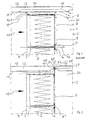
- Fig. 1 is a vertical or horizontal sectional view of a portion of an air treatment apparatus having filter cartridges, enclosed in a conventional way;
- Fig. 2 is a corresponding view of an apparatus according to the invention;
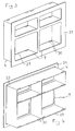
- Fig. 3 and 4 are perspective views from the front and from the rear respectively of a typical combination of filter cartridges in an apparatus according to the invention; and
- Fig. 5 and 6 are views, which correspond to Figs. 3 and 4, of a modified embodiment according to the invention.
- In Fig. 1 a
conventional apparatus 1 is shown, which comprisesfilters 2 infilter cartridges 3, which in their turn are inserted incassettes 4, which in their turn are joined to a unit, inserted in anair treatment assembly 5.Filter cartridges 3 withfilters 2 are standard components and have on one side, namely the side located downstream, an axially aligned seal 6 around the periphery, which in an axial alignment abuts a radial inner flange 7 around the cassette, to the inner end of which all around an axially alignedflange 8 is connected, which encircles an outlet opening 9. -
Air treatment assembly 5 hasouter walls 10, which e.g. comprise panels, which consist ofinner sheets 11 andouter sheets 12 with aninterior 13 between said sheets, which is empty or filled with an insulating material. Filling profiles 14, which in cross section look like handles, project towards the adjacent cassette walls and are fastened toinner sheet 11 and have the same length axially as the cassettes and are designed to fill up the cross section of the duct. - It is shown in Fig. 1, that
air 15, which has not been purified and flows into the assembly, can pass throughfilter 2 and to the lee-side 20 as leakage streams 16 between adjacent cassettes, as leakage streams 17 between the cassettes and filling profiles 14, asleakage streams 18 between the filling profiles andinner sheet 11 as well as asleakage streams 19 throughinterior 13 between the assembly walls. - Each one of these possible leakage streams are objectionable and jeopardizes the security, e.g. in operation rooms, hospitals, laboratories, research institutions etc.
- To solve these problems the present invention provides a
device 21, which radically reduces the risk of air leakage past an assembly housing or a duct designed in another way. Such a device consists of or comprises a plane sealing sheet, which preferably is most shape resistant due to the selection of a suitable material and/or the thickness of the sheet, to which sealing sheet preferably but not necessarily the adjacent cassette side or the adjacent cassette sides is (are) fastened, e.g. welded, with its (their) main surface on the air supply side, which for this purpose at least partly can haveflanges 22, bent outwards from the cassette with an angle of 90°. However, these flanges are not particularly important, and it is shown in Fig. 2, that they are not present at all, in case two cassettes abut each other, in which case available spaces can be maximally utilized and means and costs can be saved and kept low respectively. Thus, within these areas only seals 6 will seal and this is possible, because the seals axiallyabut sealing sheet 21, which in its turn is designed to completely seal against the lee-side, because the sealing sheet according to an additional very important feature according to the invention is to extend through at least a portion of the assembly wall and preferably reach the atmosphere outside the assembly. This preferably is accomplished within the area of a joint 23 betweenadjacent assembly panels 10, which joint suitably is sealed by means ofseals 24 and 25 between on one hand the sealing sheet and on the other hand paneljoint sides - Whereas seals 6 act and are influenced in an axial direction and due to the positive influence of the incoming air on the sealing force rather will have a larger sealing effect, because the air pressure differences will increase, the incoming air does not, irrespective of air pressure differences, improve the sealing of seal 24 on the side of the incoming air, and thus a
leakage stream 28 may arise in this area, which however due todevice 21 reaches the atmosphere outside the assembly, not being able to contaminate the air on the lee-side. The efficiency reduction of the assembly or the duct due toleakage stream 28 usually is completely negligible. Exactly becauseleakage stream 28 is not important for the intended function of the device, it is possible to not extendsealing sheet 21 through the entireouter wall 10 but fasten it somewhere inside the outer wall, provided apossible leakage stream 28 does not penetrate into the lee-side and is mixed with the filtered air. It is of course the simplest, the best and the most secure thing to do to extend the sealing sheet all the way throughouter wall 10 and a joint between adjacent outer wall portions respectively, a guarantee being obtained, that no leakage stream of any kind may reach the filtered purified air. - The
free edge area 29 of e.g. the lower cassette sides can be bent outwards in order to facilitate the insertion of the filter cartridges. Also, within e.g. the free end area of the upper and lower sides of the cassettes there may be openings or the like 30 for fastening devices (not shown) for the filter cartridges. -
Device 21 according to the invention certainly is very simple, but it is so ingenious, that it is quite possible to use a sealing sheet, which is not very shape resistant, because the resilience of seal 6 and its continuous exposure to the pressure difference means, that possible minor surface irregularities would be filled up and bridged over, no leakage streams arising. It is also reasonable to maintain, thatsealing sheet 21 is made even more shape resistant due to the edge fastening on all sides in an assembly or duct joint. If it is required, it is of course possible to provide said edge area with special fastening means, e.g. a certain profiling, which will counteract a bending of the sheet or every tendency to be drawn into the assembly or the duct. It is also possible to combine said fastening means with outer, not shown tightening means in order to press together twoadjacent panels 10 within each joint area. - It is a substantial advantage, that plane sheets, to be used as blanks for sealing sheets, are easily available everywhere and easily can be provided with e.g. punched
openings 9 having the required size and location. Consequently, filter cartridges and possibly cassettes can be purchased from a certain supplier, whereas the sealing sheet can be delivered from another supplier or manufactured directly on the air treatment apparatus. The cassettes are, thanks to the invention, less critical regarding sealing details and their precision, and consequently also the cassettes can be delivered from quite different types of suppliers and/or they can be manufactured from thinner and/or less expensive materials. - It is advantageous to manufacture the cassettes with e.g. through vertical walls for all the cassettes, which are vertically arranged, and with through horizontal outer walls, which is shown in the drawings. In this way additional manufacturing and cost advantages can be obtained.
- The invention is not limited to the embodiments, which have been described above and/or shown in the drawings, but it can be supplemented and altered respectively in any arbitrary manner within the scope of the inventive idea and the enclosed claims respectively. Thus, it is not necessary to use cassettes, e.g. when only one filter or one filter cassette is used. Cassettes mainly do not contribute to the sealing efficiency of the apparatus and consequently can be dispensed with in certain cases, but they are of course practical to use and forms supplementary locking and
pressure devices 30 and also make the sealing sheet more rigid. - One embodiment of the invention, in which
cassettes 4 have been reduced to holders 4', is shown in Figs. 5 and 6. These holders comprise only a remainder of cassettes, which otherwise are closed all around, within the corner areas and also in these areas additional material savings can be made, e.g. by means of triangular ortrapezoidal recesses 31, where the base is formed by or overlaps sealing sheet 21'. Those holder portions, which are disposed within vertical planes in the drawings, can have a rectangular basic shape, whereas the adjacent portions, disposed within horizontal planes, can have a trapezoidal and semi-trapezoidal basic shape respectively. Said holder portions, disposed within vertical planes, can, at their free edges, have openings or the like 30' for said tightening means, which suitably are eccentric elements, disposed on the ends of a tightening rod (not shown), applied across the width of the filter cartridges. - Increased rigidity of the apparatus, despite reduced cassette size and/or thinner sealing sheet, can be obtained by providing the latter, on its air downstream side, with a border (rim) 32 all around, having a width of one or a few centimeters. The border can be obtained by bending the sealing sheet material or by welding or soldering. It extends without interruption along and forms the outer sides of
openings 9' and housesbeams 33, preferably having the same thickness and which form and define the other opening sides and which are welded to the inner side of the border and to each other within existing crossing points respectively. The cassettes and the holders respectively are welded to the beams to the required extent.
Claims (10)
- A filtering apparatus for an air treatment apparatus (5), having very high separation percentages of the filtered air and which comprises one or several filter cartridges (3), provided with one or several filters (2), which cartridges are fastened to the air treatment apparatus and which are provided with a seal (6), which extends around the periphery and in an axial direction, on its side, which turns towards the incoming air stream, which seal axially abuts a surface, the orientation of which is radial in relation to the air stream and the apparatus respectively, which surface surrounds an outer wall (10) and an outlet opening (9), defined by each filter cartridge, characterized in that said surface comprises a sealing sheet (21), which with the exception of said opening and openings respectively (9) has a continuous radial sealing cross section through the entire filtering apparatus (5) and extends in a radial direction out through the outer wall (10) at a joint (23) between outer wall portions of the apparatus.
- A filtering apparatus according to claim 1, characterized in that each filter cartridge (3) is inserted into a cassette (4) and in that, when several cassettes are used, they are joined to a unit and a partial unit respectively, preferably having partially through and common respectively walls, particularly having outer walls, which are through for all the cassettes in a horizontal and a vertical direction respectively.
- A filtering device according to claim 1, characterized in that the sealing sheet (21; 21 ') is shape resistant to a high degree, made of a relatively rigid material and/or having a relatively large material thickness.
- A filtering apparatus according to any of claims 1-3, characterized in that the adjacent cassette side and the adjacent cassette sides respectively is (are) fastened to the sealing sheet (21), with its main surface on the side of the incoming air, which adjacent cassette side or sides for this purpose at least partially has (have) flanges (22), which are bent an angle of 90°,
- A filtering apparatus according to claim 1, characterized in that the sealing sheet (21) extends to the atmosphere outside the apparatus through a joint (23) between adjacent outer wall portions (10), which joint preferably is sealed by means of seals (24 and 25) between on the one hand the sealing sheet and on the other hand the outer wall portion joint sides (26 and 27), exposed to the sealing sheet.
- A filtering apparatus according to claim 5, characterized in that the sealing sheet (21) is made more shape resistant by means of the edge fastening all around in an assembly joint or duct joint (23) and/or in that said edge fastening area is provided with special holding means, which counteract a bending of the sheet or every tendency to being drawn into the assembly (5).
- A filtering apparatus according to any of claims 1-6, characterized in that the sealing sheet (21) is made of a separate plane sheet as a blank, which is provided with punched openings (9) with the required size and the required location.
- A filtering apparatus according to any of claims 2-7, characterized in that the cassettes are manufactured with through vertical walls for all the cassettes, arranged in a vertical direction, and with through horizontal outer walls.
- A filtering apparatus according to claims 1-8, characterized in that the cassettes are reduced to holders (4') and consist only of a remainder of cassettes, otherwise closed all around, within the corner areas, in which holders, in order to obtain additional material savings, preferably triangular or trapezoidal recesses (31) are made, in which the base is made of or overlaps the sealing sheet (21) and in which the holder portions, which are disposed within vertical planes, preferably have a rectangular basic shape, whereas the adjacent portions, disposed within horizontal planes, preferably have a trapezoidal and semi-trapezoidal basic shape, as well as in that said holder portions, disposed within vertical planes, at their free edges have openings (30') for said fastening means, which suitably are eccentric elements, disposed at the end of a tightening rod, stretched across the width of the filter cartridges.
- A filtering apparatus according to any of claims 1-9, characterized in that an increased rigidity of the apparatus, despite reduced cassette size and/or thinner sealing sheet, is obtained by providing the latter, on the air downstream side, with a border (32) all around having a width of one or a few centimeters, in that the border is made by bending the sealing sheet material or by welding or soldering, in that it extends through and along and forms the outer sides of the openings (9') and houses beams (33), preferably having the same thickness and which form and define the other opening sides and which are welded to the inner side of the border and to each other respectively within existing crossing points and in that the cassettes and the holders respectively to the existing extent are welded to the beams.
Applications Claiming Priority (3)
| Application Number | Priority Date | Filing Date | Title |
|---|---|---|---|
| SE9803626 | 1998-10-22 | ||
| SE9803626A SE512980C2 (en) | 1998-10-22 | 1998-10-22 | Filter device for air ducts or air handling units |
| PCT/SE1999/001874 WO2000023170A1 (en) | 1998-10-22 | 1999-10-19 | Filtering apparatus for air treatment apparatus |
Publications (2)
| Publication Number | Publication Date |
|---|---|
| EP1126907A1 EP1126907A1 (en) | 2001-08-29 |
| EP1126907B1 true EP1126907B1 (en) | 2007-02-21 |
Family
ID=20413057
Family Applications (1)
| Application Number | Title | Priority Date | Filing Date |
|---|---|---|---|
| EP99970621A Expired - Lifetime EP1126907B1 (en) | 1998-10-22 | 1999-10-19 | Filtering apparatus for air treatment apparatus |
Country Status (14)
| Country | Link |
|---|---|
| US (1) | US6562095B1 (en) |
| EP (1) | EP1126907B1 (en) |
| KR (1) | KR100561024B1 (en) |
| AT (1) | ATE354417T1 (en) |
| AU (1) | AU1427400A (en) |
| CZ (1) | CZ295159B6 (en) |
| DE (1) | DE69935240T2 (en) |
| DK (1) | DK1126907T3 (en) |
| ES (1) | ES2281982T3 (en) |
| NO (1) | NO325334B1 (en) |
| PT (1) | PT1126907E (en) |
| RU (1) | RU2236283C2 (en) |
| SE (1) | SE512980C2 (en) |
| WO (1) | WO2000023170A1 (en) |
Cited By (1)
| Publication number | Priority date | Publication date | Assignee | Title |
|---|---|---|---|---|
| CN106823611A (en) * | 2017-03-03 | 2017-06-13 | 陈泳东 | A kind of filter cartridge type dust removal unit |
Families Citing this family (11)
| Publication number | Priority date | Publication date | Assignee | Title |
|---|---|---|---|---|
| SE521794C2 (en) * | 2002-04-05 | 2003-12-09 | Sandvik Ab | Manufacturing process for a molybdenum silicon type heating element, as well as a heating element |
| SE521796C2 (en) * | 2002-04-05 | 2003-12-09 | Sandvik Ab | Process for manufacturing a molybdenum silicon type heating element and a heating element |
| AU2003219631A1 (en) * | 2002-04-05 | 2003-10-27 | Sandvik Ab | Method of making a heating element of molybdenum silicide type |
| CA2430510C (en) * | 2003-05-30 | 2008-04-08 | B.G.E. Service & Supply Ltd. | A method of preventing air bypass in a filter bank and a filter assembly |
| US20110041470A1 (en) * | 2006-08-25 | 2011-02-24 | Pall Corporation | Fluid assemblies comprising a purification element |
| KR20080035477A (en) * | 2006-10-19 | 2008-04-23 | 닛토덴코 가부시키가이샤 | Filter unit and filter unit panel |
| KR101047517B1 (en) | 2009-10-27 | 2011-07-07 | 대기산업 주식회사 | Automotive Air Filter Assembly |
| RU2432983C1 (en) * | 2010-03-05 | 2011-11-10 | Общество с ограниченной ответственностью "АСИНТЕК" | Air filter |
| DE102013105723A1 (en) * | 2013-06-04 | 2014-12-04 | Torsten Herrmann | Filter system and method for cleaning the intake air of a gas turbine |
| CN104637560B (en) * | 2013-11-11 | 2017-07-25 | 中国辐射防护研究院 | A kind of interchangeable charcoal remove iodine filter |
| US20220297044A1 (en) * | 2021-03-16 | 2022-09-22 | Carrier Corporation | Multi-compartment negative air filtration |
Family Cites Families (15)
| Publication number | Priority date | Publication date | Assignee | Title |
|---|---|---|---|---|
| US3247652A (en) * | 1963-01-21 | 1966-04-26 | Henry C Annas | Means for mounting filter units in air ducts |
| US3552104A (en) * | 1968-10-07 | 1971-01-05 | American Air Filter Co | Two-staged compression of a sealing gasket |
| US4233044A (en) * | 1976-05-13 | 1980-11-11 | Flanders Filters, Inc. | Self-cleaning fluid sealed air filter |
| US4883510A (en) * | 1988-02-12 | 1989-11-28 | Giambattista Giusti | Gas inlet construction for fabric filter dust collections |
| SU1701347A1 (en) * | 1989-07-26 | 1991-12-30 | Тверской политехнический институт | Device for filtering gaseous medium |
| SU1725981A1 (en) * | 1990-03-26 | 1992-04-15 | Государственный научно-исследовательский институт по промышленной и санитарной очистке газов | Folding fibrous filter |
| RU2049527C1 (en) * | 1991-11-29 | 1995-12-10 | Зеликсон Борис Малкиэлевич | Filtering module with regenerative inserts and air fine filter |
| US5443625A (en) * | 1994-01-18 | 1995-08-22 | Schaffhausen; John M. | Air filtering fixture |
| JP3131540B2 (en) * | 1994-08-04 | 2001-02-05 | 日本碍子株式会社 | Support structure of filter element in dust collector |
| DE19502366C2 (en) * | 1995-01-26 | 1998-02-26 | Freudenberg Carl Fa | Cassette filter |
| DE19611817C2 (en) | 1996-03-26 | 2000-10-26 | Schako Metallwarenfabrik | Filter box |
| DE19641127A1 (en) | 1996-10-05 | 1998-04-09 | Meissner & Wurst | Clean room ceiling, preferably grid ceiling |
| US6162270A (en) * | 1997-06-07 | 2000-12-19 | N.S.Technologies Inc. | Downdraft paint booth and filters therefor |
| DE29822871U1 (en) * | 1998-12-23 | 1999-02-25 | Thomas Josef Heimbach GmbH & Co., 52353 Düren | Filter device |
| US6348085B1 (en) * | 1999-11-10 | 2002-02-19 | Donaldson Company, Inc. | Filter arrangement and methods |
-
1998
- 1998-10-22 SE SE9803626A patent/SE512980C2/en not_active IP Right Cessation
-
1999
- 1999-10-19 PT PT99970621T patent/PT1126907E/en unknown
- 1999-10-19 ES ES99970621T patent/ES2281982T3/en not_active Expired - Lifetime
- 1999-10-19 DK DK99970621T patent/DK1126907T3/en active
- 1999-10-19 CZ CZ20011393A patent/CZ295159B6/en not_active IP Right Cessation
- 1999-10-19 US US09/807,717 patent/US6562095B1/en not_active Expired - Lifetime
- 1999-10-19 KR KR1020017004488A patent/KR100561024B1/en not_active Expired - Fee Related
- 1999-10-19 AU AU14274/00A patent/AU1427400A/en not_active Abandoned
- 1999-10-19 DE DE69935240T patent/DE69935240T2/en not_active Expired - Lifetime
- 1999-10-19 WO PCT/SE1999/001874 patent/WO2000023170A1/en not_active Ceased
- 1999-10-19 AT AT99970621T patent/ATE354417T1/en active
- 1999-10-19 RU RU2001111031/15A patent/RU2236283C2/en not_active IP Right Cessation
- 1999-10-19 EP EP99970621A patent/EP1126907B1/en not_active Expired - Lifetime
-
2001
- 2001-04-19 NO NO20011922A patent/NO325334B1/en not_active IP Right Cessation
Cited By (1)
| Publication number | Priority date | Publication date | Assignee | Title |
|---|---|---|---|---|
| CN106823611A (en) * | 2017-03-03 | 2017-06-13 | 陈泳东 | A kind of filter cartridge type dust removal unit |
Also Published As
| Publication number | Publication date |
|---|---|
| NO20011922D0 (en) | 2001-04-19 |
| KR20010080070A (en) | 2001-08-22 |
| SE512980C2 (en) | 2000-06-12 |
| DK1126907T3 (en) | 2007-04-30 |
| AU1427400A (en) | 2000-05-08 |
| NO20011922L (en) | 2001-04-19 |
| EP1126907A1 (en) | 2001-08-29 |
| PT1126907E (en) | 2007-05-31 |
| SE9803626L (en) | 2000-04-23 |
| SE9803626D0 (en) | 1998-10-22 |
| CZ20011393A3 (en) | 2001-10-17 |
| DE69935240T2 (en) | 2007-11-08 |
| DE69935240D1 (en) | 2007-04-05 |
| US6562095B1 (en) | 2003-05-13 |
| ES2281982T3 (en) | 2007-10-01 |
| KR100561024B1 (en) | 2006-03-16 |
| RU2236283C2 (en) | 2004-09-20 |
| WO2000023170A1 (en) | 2000-04-27 |
| ATE354417T1 (en) | 2007-03-15 |
| NO325334B1 (en) | 2008-03-31 |
| CZ295159B6 (en) | 2005-06-15 |
Similar Documents
| Publication | Publication Date | Title |
|---|---|---|
| US6562095B1 (en) | Filtering apparatus for air treatment apparatus | |
| CN101163535B (en) | Air filter device | |
| CN102159297B (en) | Air cleaner assembly and its parts | |
| US7090713B2 (en) | Deep filter element suitable for replacing a shallow filter element and having a support frame made from thin stock | |
| US20030066274A1 (en) | Method and apparatus for assembling an expandable and disposable media filter | |
| RU2335836C2 (en) | Updated metal transverse profile for feeder switchboard cases | |
| US20030066424A1 (en) | Method and apparatus for assembling an expandable media filter | |
| US6638333B2 (en) | Method and apparatus for assembling an expandable media filter with spacing ribbons | |
| KR20080069996A (en) | Air Filter Arrangements, Assemblies, and Methods | |
| EP0951335B1 (en) | Air filter | |
| CA3183710A1 (en) | Air filter and gasket for the same | |
| US4124362A (en) | Snap together header and cell side assembly | |
| JP4584426B2 (en) | Distillation tower separation wall | |
| RU2001111031A (en) | Filtering unit for air handling devices | |
| BR0311174B1 (en) | cassette filter for gas purification. | |
| TWM655965U (en) | Air curtain device and its filter assembly | |
| AU2002332022B2 (en) | Expandable and disposable media filter | |
| WO2001050072A1 (en) | Filter mounting channel | |
| JP3295659B2 (en) | Air filter device | |
| TWI887985B (en) | Air curtain device and filter assembly thereof | |
| CN210332037U (en) | Filter for ventilation system and a ventilation system | |
| US7481007B2 (en) | Sealing arrangement | |
| EP4464396B1 (en) | Filter element | |
| JP4660392B2 (en) | Air filter and air filter manufacturing method | |
| RU2072250C1 (en) | Fine filter based on fibrous filter materials |
Legal Events
| Date | Code | Title | Description |
|---|---|---|---|
| PUAI | Public reference made under article 153(3) epc to a published international application that has entered the european phase |
Free format text: ORIGINAL CODE: 0009012 |
|
| 17P | Request for examination filed |
Effective date: 20010319 |
|
| AK | Designated contracting states |
Kind code of ref document: A1 Designated state(s): AT BE CH CY DE DK ES FI FR GB GR IE IT LI LU MC NL PT SE |
|
| RAP1 | Party data changed (applicant data changed or rights of an application transferred) |
Owner name: FLAEKT WOODS AB |
|
| 19U | Interruption of proceedings before grant |
Effective date: 20040314 |
|
| 19W | Proceedings resumed before grant after interruption of proceedings |
Effective date: 20040812 |
|
| GRAP | Despatch of communication of intention to grant a patent |
Free format text: ORIGINAL CODE: EPIDOSNIGR1 |
|
| GRAS | Grant fee paid |
Free format text: ORIGINAL CODE: EPIDOSNIGR3 |
|
| GRAA | (expected) grant |
Free format text: ORIGINAL CODE: 0009210 |
|
| AK | Designated contracting states |
Kind code of ref document: B1 Designated state(s): AT BE CH CY DE DK ES FI FR GB GR IE IT LI LU MC NL PT SE |
|
| REG | Reference to a national code |
Ref country code: GB Ref legal event code: FG4D |
|
| REG | Reference to a national code |
Ref country code: CH Ref legal event code: EP |
|
| REG | Reference to a national code |
Ref country code: SE Ref legal event code: TRGR |
|
| REF | Corresponds to: |
Ref document number: 69935240 Country of ref document: DE Date of ref document: 20070405 Kind code of ref document: P |
|
| REG | Reference to a national code |
Ref country code: IE Ref legal event code: FG4D |
|
| REG | Reference to a national code |
Ref country code: DK Ref legal event code: T3 Ref country code: CH Ref legal event code: NV Representative=s name: INTERPAT LAW AG |
|
| REG | Reference to a national code |
Ref country code: GR Ref legal event code: EP Ref document number: 20070401239 Country of ref document: GR |
|
| REG | Reference to a national code |
Ref country code: PT Ref legal event code: SC4A Free format text: AVAILABILITY OF NATIONAL TRANSLATION Effective date: 20070521 |
|
| ET | Fr: translation filed | ||
| REG | Reference to a national code |
Ref country code: ES Ref legal event code: FG2A Ref document number: 2281982 Country of ref document: ES Kind code of ref document: T3 |
|
| PLBE | No opposition filed within time limit |
Free format text: ORIGINAL CODE: 0009261 |
|
| STAA | Information on the status of an ep patent application or granted ep patent |
Free format text: STATUS: NO OPPOSITION FILED WITHIN TIME LIMIT |
|
| 26N | No opposition filed |
Effective date: 20071122 |
|
| PG25 | Lapsed in a contracting state [announced via postgrant information from national office to epo] |
Ref country code: MC Free format text: LAPSE BECAUSE OF NON-PAYMENT OF DUE FEES Effective date: 20071031 |
|
| PG25 | Lapsed in a contracting state [announced via postgrant information from national office to epo] |
Ref country code: CY Free format text: LAPSE BECAUSE OF FAILURE TO SUBMIT A TRANSLATION OF THE DESCRIPTION OR TO PAY THE FEE WITHIN THE PRESCRIBED TIME-LIMIT Effective date: 20070221 |
|
| PG25 | Lapsed in a contracting state [announced via postgrant information from national office to epo] |
Ref country code: LU Free format text: LAPSE BECAUSE OF NON-PAYMENT OF DUE FEES Effective date: 20071019 |
|
| PGFP | Annual fee paid to national office [announced via postgrant information from national office to epo] |
Ref country code: PT Payment date: 20140421 Year of fee payment: 16 |
|
| PGFP | Annual fee paid to national office [announced via postgrant information from national office to epo] |
Ref country code: IE Payment date: 20141015 Year of fee payment: 16 Ref country code: CH Payment date: 20141017 Year of fee payment: 16 Ref country code: GR Payment date: 20141024 Year of fee payment: 16 Ref country code: ES Payment date: 20141028 Year of fee payment: 16 |
|
| PGFP | Annual fee paid to national office [announced via postgrant information from national office to epo] |
Ref country code: NL Payment date: 20141017 Year of fee payment: 16 Ref country code: AT Payment date: 20141022 Year of fee payment: 16 |
|
| PGFP | Annual fee paid to national office [announced via postgrant information from national office to epo] |
Ref country code: IT Payment date: 20141024 Year of fee payment: 16 |
|
| REG | Reference to a national code |
Ref country code: DE Ref legal event code: R082 Ref document number: 69935240 Country of ref document: DE Representative=s name: BISCHOF & PARTNER RECHTSANWAELTE PARTNERSCHAFT, DE |
|
| PGFP | Annual fee paid to national office [announced via postgrant information from national office to epo] |
Ref country code: BE Payment date: 20141017 Year of fee payment: 16 |
|
| REG | Reference to a national code |
Ref country code: FR Ref legal event code: PLFP Year of fee payment: 17 |
|
| PGFP | Annual fee paid to national office [announced via postgrant information from national office to epo] |
Ref country code: DK Payment date: 20151023 Year of fee payment: 17 |
|
| PGFP | Annual fee paid to national office [announced via postgrant information from national office to epo] |
Ref country code: FI Payment date: 20151019 Year of fee payment: 17 Ref country code: DE Payment date: 20151026 Year of fee payment: 17 Ref country code: GB Payment date: 20151027 Year of fee payment: 17 |
|
| PGFP | Annual fee paid to national office [announced via postgrant information from national office to epo] |
Ref country code: FR Payment date: 20151102 Year of fee payment: 17 Ref country code: SE Payment date: 20151022 Year of fee payment: 17 |
|
| REG | Reference to a national code |
Ref country code: PT Ref legal event code: MM4A Free format text: LAPSE DUE TO NON-PAYMENT OF FEES Effective date: 20160419 |
|
| REG | Reference to a national code |
Ref country code: CH Ref legal event code: PL |
|
| REG | Reference to a national code |
Ref country code: AT Ref legal event code: MM01 Ref document number: 354417 Country of ref document: AT Kind code of ref document: T Effective date: 20151019 |
|
| REG | Reference to a national code |
Ref country code: NL Ref legal event code: MM Effective date: 20151101 |
|
| REG | Reference to a national code |
Ref country code: GR Ref legal event code: ML Ref document number: 20070401239 Country of ref document: GR Effective date: 20160506 |
|
| REG | Reference to a national code |
Ref country code: IE Ref legal event code: MM4A |
|
| PG25 | Lapsed in a contracting state [announced via postgrant information from national office to epo] |
Ref country code: CH Free format text: LAPSE BECAUSE OF NON-PAYMENT OF DUE FEES Effective date: 20151031 Ref country code: IT Free format text: LAPSE BECAUSE OF NON-PAYMENT OF DUE FEES Effective date: 20151019 Ref country code: GR Free format text: LAPSE BECAUSE OF NON-PAYMENT OF DUE FEES Effective date: 20160506 Ref country code: LI Free format text: LAPSE BECAUSE OF NON-PAYMENT OF DUE FEES Effective date: 20151031 |
|
| PG25 | Lapsed in a contracting state [announced via postgrant information from national office to epo] |
Ref country code: AT Free format text: LAPSE BECAUSE OF NON-PAYMENT OF DUE FEES Effective date: 20151019 Ref country code: PT Free format text: LAPSE BECAUSE OF NON-PAYMENT OF DUE FEES Effective date: 20160419 Ref country code: NL Free format text: LAPSE BECAUSE OF NON-PAYMENT OF DUE FEES Effective date: 20151101 |
|
| PG25 | Lapsed in a contracting state [announced via postgrant information from national office to epo] |
Ref country code: IE Free format text: LAPSE BECAUSE OF NON-PAYMENT OF DUE FEES Effective date: 20151019 |
|
| REG | Reference to a national code |
Ref country code: ES Ref legal event code: FD2A Effective date: 20170202 |
|
| PG25 | Lapsed in a contracting state [announced via postgrant information from national office to epo] |
Ref country code: ES Free format text: LAPSE BECAUSE OF NON-PAYMENT OF DUE FEES Effective date: 20151020 |
|
| REG | Reference to a national code |
Ref country code: DE Ref legal event code: R119 Ref document number: 69935240 Country of ref document: DE |
|
| REG | Reference to a national code |
Ref country code: DK Ref legal event code: EBP Effective date: 20161031 |
|
| GBPC | Gb: european patent ceased through non-payment of renewal fee |
Effective date: 20161019 |
|
| REG | Reference to a national code |
Ref country code: FR Ref legal event code: ST Effective date: 20170630 |
|
| PG25 | Lapsed in a contracting state [announced via postgrant information from national office to epo] |
Ref country code: DE Free format text: LAPSE BECAUSE OF NON-PAYMENT OF DUE FEES Effective date: 20170503 Ref country code: FR Free format text: LAPSE BECAUSE OF NON-PAYMENT OF DUE FEES Effective date: 20161102 Ref country code: BE Free format text: LAPSE BECAUSE OF NON-PAYMENT OF DUE FEES Effective date: 20151031 Ref country code: FI Free format text: LAPSE BECAUSE OF NON-PAYMENT OF DUE FEES Effective date: 20161019 Ref country code: GB Free format text: LAPSE BECAUSE OF NON-PAYMENT OF DUE FEES Effective date: 20161019 |
|
| PG25 | Lapsed in a contracting state [announced via postgrant information from national office to epo] |
Ref country code: SE Free format text: LAPSE BECAUSE OF NON-PAYMENT OF DUE FEES Effective date: 20161020 |
|
| PG25 | Lapsed in a contracting state [announced via postgrant information from national office to epo] |
Ref country code: DK Free format text: LAPSE BECAUSE OF NON-PAYMENT OF DUE FEES Effective date: 20161031 |