EP1126665A2 - Source learning for multi-path backplane data switch - Google Patents
Source learning for multi-path backplane data switch Download PDFInfo
- Publication number
- EP1126665A2 EP1126665A2 EP01101605A EP01101605A EP1126665A2 EP 1126665 A2 EP1126665 A2 EP 1126665A2 EP 01101605 A EP01101605 A EP 01101605A EP 01101605 A EP01101605 A EP 01101605A EP 1126665 A2 EP1126665 A2 EP 1126665A2
- Authority
- EP
- European Patent Office
- Prior art keywords
- source address
- packet
- source
- switching module
- backplane
- Prior art date
- Legal status (The legal status is an assumption and is not a legal conclusion. Google has not performed a legal analysis and makes no representation as to the accuracy of the status listed.)
- Granted
Links
- 239000004744 fabric Substances 0.000 claims description 84
- 230000015654 memory Effects 0.000 claims description 20
- 238000000034 method Methods 0.000 claims description 19
- 230000005540 biological transmission Effects 0.000 claims 1
- 230000006870 function Effects 0.000 description 11
- 238000010586 diagram Methods 0.000 description 10
- 238000013479 data entry Methods 0.000 description 4
- 238000004891 communication Methods 0.000 description 2
- 230000002457 bidirectional effect Effects 0.000 description 1
- 239000002131 composite material Substances 0.000 description 1
- 239000011159 matrix material Substances 0.000 description 1
- 238000012545 processing Methods 0.000 description 1
- 230000010076 replication Effects 0.000 description 1
- 238000012552 review Methods 0.000 description 1
- 238000012360 testing method Methods 0.000 description 1
Images



Classifications
-
- H—ELECTRICITY
- H04—ELECTRIC COMMUNICATION TECHNIQUE
- H04L—TRANSMISSION OF DIGITAL INFORMATION, e.g. TELEGRAPHIC COMMUNICATION
- H04L12/00—Data switching networks
- H04L12/28—Data switching networks characterised by path configuration, e.g. LAN [Local Area Networks] or WAN [Wide Area Networks]
- H04L12/46—Interconnection of networks
- H04L12/4641—Virtual LANs, VLANs, e.g. virtual private networks [VPN]
-
- H—ELECTRICITY
- H04—ELECTRIC COMMUNICATION TECHNIQUE
- H04L—TRANSMISSION OF DIGITAL INFORMATION, e.g. TELEGRAPHIC COMMUNICATION
- H04L12/00—Data switching networks
- H04L12/54—Store-and-forward switching systems
- H04L12/56—Packet switching systems
- H04L12/5601—Transfer mode dependent, e.g. ATM
-
- H—ELECTRICITY
- H04—ELECTRIC COMMUNICATION TECHNIQUE
- H04L—TRANSMISSION OF DIGITAL INFORMATION, e.g. TELEGRAPHIC COMMUNICATION
- H04L45/00—Routing or path finding of packets in data switching networks
- H04L45/24—Multipath
-
- H—ELECTRICITY
- H04—ELECTRIC COMMUNICATION TECHNIQUE
- H04L—TRANSMISSION OF DIGITAL INFORMATION, e.g. TELEGRAPHIC COMMUNICATION
- H04L49/00—Packet switching elements
- H04L49/20—Support for services
- H04L49/201—Multicast operation; Broadcast operation
- H04L49/203—ATM switching fabrics with multicast or broadcast capabilities
-
- H—ELECTRICITY
- H04—ELECTRIC COMMUNICATION TECHNIQUE
- H04L—TRANSMISSION OF DIGITAL INFORMATION, e.g. TELEGRAPHIC COMMUNICATION
- H04L49/00—Packet switching elements
- H04L49/40—Constructional details, e.g. power supply, mechanical construction or backplane
- H04L49/405—Physical details, e.g. power supply, mechanical construction or backplane of ATM switches
-
- H—ELECTRICITY
- H04—ELECTRIC COMMUNICATION TECHNIQUE
- H04L—TRANSMISSION OF DIGITAL INFORMATION, e.g. TELEGRAPHIC COMMUNICATION
- H04L12/00—Data switching networks
- H04L12/54—Store-and-forward switching systems
- H04L12/56—Packet switching systems
- H04L12/5601—Transfer mode dependent, e.g. ATM
- H04L2012/5638—Services, e.g. multimedia, GOS, QOS
- H04L2012/5665—Interaction of ATM with other protocols
Definitions
- the present invention relates to devices for switching data and, more particularly, to method and apparatus for source learning in multi-path backplane data switches.
- Data switches interconnect network devices residing in different parts of a network.
- Such switches typically include network interface modules having ports supporting external network devices.
- a conventional backplane used to interconnect network interface modules in such data switches has a common path for all packets between two network interface modules.
- the network interface module on the ingress side of the backplane typically propagates inbound packets to all of the other network interface modules. Accordingly, the network interface modules on the egress side of such data switches are typically responsible for individually reviewing the packets and deciding whether or not to "claim” them for forwarding out of the switch.
- the protocol in such switches typically also includes a method and apparatus for dynamically establishing associations between the network interface modules and the external network devices they support.
- Such associations typically are established in conjunction with propagation of packets over the backplane by having network interface modules on the ingress side review the source addresses in inbound packets and mark the packets from sources that they do not know as "unknown.”
- the packets marked as unknown are typically claimed by a management interface module, which typically resides on the backplane.
- the management interface module is typically used to claim such marked packets and to update the source address/network switching module associations as required.
- the function on a switch which establishes source address/network interface module associations by reviewing source addresses in inbound packets is often called "source learning.”
- a method of source learning in a data switch has a plurality of switching modules interconnected over a backplane.
- the backplane includes a unicast fabric and a multicast fabric.
- a packet having a source address is received on a first switching module.
- a memory associated with the first switching module is looked up to determine if the source address is found in the memory.
- a source learning indicator for the packet is set if the source address is not found in the memory associated with the first switching module.
- the packet is transmitted over the backplane.
- the source address is associated with the first switching module.
- a multi-path data switch in another embodiment, includes a backplane having a unicast fabric and a multicast fabric and a plurality of switching modules coupled to the backplane. Each switching module includes an associated memory,
- the multi-path data switch also includes a management interface module coupled to the multicast fabric of the backplane.
- the unicast fabric couples each pair of switching modules on a unicast path
- the multicast fabric couples the switching modules and the management interface module on a multicast path
- the management interface module receives a packet having a source address from a particular switching module over the multicast path and associates the source address with the particular switching module.
- an apparatus for packet forwarding in a multi-path data switch having a plurality of switching modules.
- the apparatus includes: means for checking for each inbound packet whether the packet has a known destination address; means for checking for each inbound packet whether the packet has a known source address; means for forwarding each packet having a known destination address over a switch backplane on a unicast path, unless the packet has an unknown source address; and means for forwarding each packet having a known destination address and an unknown source address over the switching backplane on a multicast path.
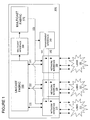
- FIG. 1 illustrates a switch 100 including network interface modules 110, 120 and 130.
- the switch may also be referred to as a data switch, as a data communication switch, or as other designations used by those skilled in the art.
- the network interface modules may also be referred to as switching modules, or as other designations used by those skilled in the art.
- the network interface modules 110, 120 and 130 are operatively coupled to LANs 111, 121, and 131, respectively.
- the switch 100 also includes a management interface module 140, a unicast fabric 150, a multicast interface 160 and a multicast fabric 170.
- the network interface modules 110, 120, and 130 communicate with the unicast fabric 150 via bidirectional signals 112, 122, and 132, and preferably serve to associate routing information with addresses, cellify data packets, and perform other look-up functions.
- the unicast fabric 150 preferably is used as the routing link when the source and destination addresses are known.
- the multicast interface 160 is operatively coupled to the unicast fabric 150 and to the multicast fabric 170.
- the multicast interface 160 preferably receives an input signal from the unicast fabric 150 and provides an output signal to the multicast fabric 170.
- the multicast interface 160 may also receive other signals and provide them to the multicast fabric 170.
- the output signal may include the input signal, the other signals, or a composite of the input signals and some or all of the other signals.
- the multicast fabric 170 preferably provides the input signal to the network interface modules for source learning when either the source address or the destination address is unknown.
- the multicast fabric 170 is operatively coupled to the multicast interface 160, to the management interface module 140, and to the network interface modules 110, 120, and 130.
- the multicast fabric 170 preferably is used as the routing link when either the source address or the destination address is not known, or when both the source and destination addresses are not known.
- the management interface module 140 is operatively coupled to the multicast fabric 170 and to the network interface modules 110, 120, and 130.
- the management interface module 140 preferably is used to discard packets and update addresses as required. It will be appreciated that the multicast interface 160 and the management interface module 140 may share the same logic block.
- FIG. 2 is a block diagram of a network interface module 200, which is representative of all network interface modules in one embodiment of the present invention.
- the network interface module 200 includes an access controller 210, a switching controller 220, and a fabric controller 230.
- the access controller 210 preferably includes a simple physical layer device (PHY device), which is coupled to LANs 205.
- PHY device simple physical layer device
- the access controller 210 preferably receives packets off LANs 205 and transmits them to the switching controller 220.
- the access controller 210 preferably also receives packets from the switching controller 220 and transmits them to the LANs 205.
- the switching controller 220 is coupled to modules for facilitating flow integrity, including a switching data module 222 and a content addressable memory (CAM) 221.
- the switching controller 220 preferably receives packets from the access controller 210, and performs a local CAM lookup using the CAM 221 to retrieve CAM data.
- the switching controller preferably also performs a switching data lookup by providing CAM data to the switching data module 222 to retrieve switching data.
- the switching data may also be referred to as forwarding data.
- the switching controller uses the CAM data and the switching data to process the packets, subjects the packets to flow integrity, and forwards the packets to the fabric controller 230.
- the switching controller 220 is also coupled to a switching control update signal 142, which enables the switching controller 220 to update the CAM 221 with further addresses.
- the fabric controller 230 is coupled to modules for facilitating flow integrity, including a fabric data module 233, a pseudo CAM 232, and a VLAN finder module 231.
- the fabric controller 230 preferably receives packets from the switching controller 220, and preferably performs a local CAM lookup with either the pseudo CAM 232 or the VLAN finder module 231.
- the fabric controller preferably also subjects the packets to ingress flow integrity such that the packets are converted into cells, and then preferably forwards those cells out of the network interface module 200.
- the fabric controller 230 is also coupled to a fabric control update signal 141 which preferably enables the fabric controller 230 to discard packets for a period of time, which, for example, may have been predetermined.
- This discard function preferably allows time for the switching controller 220 to update the CAM 221 with a new address.
- the discard function preferably also allows packets from the multicast fabric 170 to arrive at their destination before packets from the unicast fabric 150 are allowed to propagate to the same destination.
- One embodiment of the present invention is directed to a novel flow integrity technique using multiple flow path backplanes while performing source learning.
- packets with either an unknown destination address or an unknown source address are transmitted to a multicast fabric for queuing, replication, and forwarding.
- packets with known destination and source addresses are transmitted to a unicast fabric for queuing and forwarding to a single network interface module on a point-to-point path.
- the switch in this embodiment preferably is capable of processing and routing packets, wherein each packet presents one of the following four properties to the network interface modules: (1) unknown destination and unknown source; (2) unknown destination and known source; (3) known destination and unknown source; and (4). known destination and known source.
- the source and destination addresses are known, no source learning typically takes place and therefore flow integrity is not an issue.
- a packet is received on a physical port of a network interface module (310), which may be similar to the network interface module 200 of Figure 2.
- a look-up operation preferably is performed to find source and destination addresses (320). Unless both the source and destination addresses are found (330), another query preferably is performed, as is the case here, to see if just the source address is found (340). If the source address is not found (340), as is the case here, a source virtual port number (SVPN) preferably is applied to the packet, and a source CAM index (SCI) preferably is set as invalid (350).
- SVPN source virtual port number
- SCI source CAM index
- the packet preferably is operated on to determine its virtual local area network (VLAN) identification (ID) from the SCI or SVPN (405).
- VLAN ID preferably is determined from the SVPN since the SCI has been set as invalid.
- an SCI-VLAN entry is looked for in the VLAN finder module using the VLAN ID to determine whether a discard indicator is set in the SCI-VLAN entry (410).
- the setting of the discard indicator in the SCI-VLAN entry preferably indicates that the packet is from the network device whose address is undergoing source learning. If the discard indicator is set (415), the packet preferably is discarded (475), and packets from the same network device preferably are discarded until the discard indicator is no longer set.
- a pseudo CAM look-up key preferably is generated from the destination address and the VLAN ID (420).
- the pseudo CAM look-up key preferably is used to determine a destination CAM index (DCI) and a fabric data index (FDI) (425). Since the destination address is unknown in this case, a default destination CAM index (DCI) preferably is used.
- the pseudo CAM look-up key preferably is also used to retrieve a pseudo CAM entry. If a discard indicator is set in the retrieved pseudo CAM entry (430), the packet preferably is discarded (475).
- the setting of the discard indicator in the pseudo CAM entry preferably indicates that the packet is destined to the network device whose address is undergoing source learning. Thus, as long as the discard indicator is set, all packets destined to the same network device preferably are discarded.
- the discard indicator is not set in the pseudo CAM entry in this case, and the packet preferably is not discarded.
- the FDI preferably is used to determine a destination interface ID and a multicast group ID (435).
- the DCI preferably is applied to the packet (445). Since the destination address is unknown in this case, the DCI preferably has been set as default, which preferably instructs a flood of the network interface modules.
- the packets preferably are segmented into cells (450). The cells preferably are then given a source interface ID, the destination interface ID, and the multicast group ID (455). In this case, before the cells are transmitted (470). over the multicast fabric, the destination interface ID preferably is set to the multicast group ID and a source learning indicator preferably is set in the cells (465) since the SCI is invalid(460).
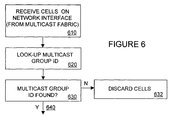
- the network interface module on receipt of the cells from the multicast fabric (610), the network interface module preferably performs a look-up operation of the multicast group ID (620) to determine whether or not to transmit the cells, i.e., the packet, out of its ports. If the multicast group ID is found (630), the cells preferably are reassembled (520) into the packet as illustrated in Figure 5. If the DCI indicates flood (530), as is the case here, the packet preferably is transmitted out of all ports (532). For example, the packets preferably flood all ports of the network interface module if the DCI is the default DCI.
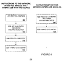
- the management interface module When the network interface modules receive the transmitted cells (610) as illustrated in Figure 6, the management interface module preferably also receives the transmitted cells (710) as illustrated in Figure 7. Once the cells have been received by the management interface module, an operation preferably is performed to determine if the source learning indicator is set (720). In this case, the source learning indicator has been set and, as such, the management interface module preferably instructs the network interface modules to perform a number of functions (750) including but not limited to the following.
- the switching controller 220 coupled to the network device whose address is undergoing source learning preferably is instructed by the switching control update signal 142 to add a source address of the network device to the CAM 221 (800).
- the fabric controller 230 preferably is instructed by the fabric control update signal 141 to add a SCI-VLAN entry including a discard indicator to the VLAN Finder Module 231 (810).
- the discard indicator preferably causes the fabric controller 230 to discard packets from the network device whose address is undergoing source learning for a period, which, for example, may have been predetermined. In other embodiments, the period for discarding packets may be dynamically determined.
- the management interface module preferably instructs the fabric controller 230 using the fabric control update signal 141 to add a pseudo CAM entry to the pseudo CAM 232 (820) and a fabric data entry (830) to the fabric data module 233, respectively.
- the management interface module preferably instructs the network interface modules that are not coupled to the network device whose address is undergoing source learning to add a pseudo CAM entry including a discard indicator to their respective pseudo CAMs using their respective fabric control update signals (840).
- the discard indicator preferably causes the respective fabric controllers of these network interface modules to discard packets destined to the network device whose address is undergoing source learning.
- the management interface module preferably instructs the respective fabric controllers of the network interface modules that are not interfacing with the network device whose address is undergoing source learning to add a fabric data entry to their respective fabric data modules (850).
- the discard conditions preferably are removed after an interval passes to ensure that all the packets associated with that network device clear the multicast fabric.
- the interval for example, may have been predetermined.
- the packets associated with that network device preferably are allowed to flow over the unicast fabric since both the destination and source addresses are now known to the switch.
- a packet is received on a physical port of a network interface module (310), which may be similar to the network interface module 200 of Figure 2.
- a look-up operation preferably is performed to find source and destination addresses (320). Unless both the source and destination addresses are found (330), another query preferably is performed, as is the case here, to see if just the source address is found (340). If the source address is found (340), as is the case here, the packet preferably is outputted (400) with the source CAM index (SCI) applied (342).
- SCI source CAM index
- the packet (400) preferably is operated on to determine its virtual local area network (VLAN) identification (ID) from the SCI or SVPN (405).
- VLAN ID preferably is determined from the SCI since the source address is known.
- an SCI-VLAN entry is looked for in the VLAN finder module using the VLAN ID to determine whether a discard indicator is set in the SCI-VLAN entry (410). If the discard indicator is set (415), the packet preferably is discarded (475), and packets from the same network device as the packet preferably are discarded until the discard indicator is no longer set.
- a pseudo CAM look-up key preferably is generated from the destination address and the VLAN ID (420).
- the pseudo CAM look-up key preferably is used to determine a destination CAM index (DCI) and a fabric data index (FDI) (425). Since the destination address is unknown in this case, a default destination CAM index (DCI) preferably is used.
- the pseudo CAM look-up key preferably is also used to retrieve a pseudo CAM entry. If a discard indicator is set in the retrieved pseudo CAM entry (430), the packet preferably is discarded (475). As long as the discard indicator is set, all packets destined to the same network device as the packet preferably are discarded. The discard indicator is not set in the pseudo CAM entry in this case, and the packet preferably is not discarded.
- the FDI preferably is used to determine a destination interface ID and a multicast group ID (435).
- the DCI preferably is applied to the packet (445). Since the destination address is unknown in this case, the DCI preferably has been set as default, which preferably instructs a flood of the network interface modules.
- the packets preferably are segmented into cells (450). Prior to being transmitted (470), the cells preferably are given a source interface ID, the destination interface ID, and the multicast group ID (455).
- the network interface module on receipt of the cells from the multicast fabric (610), the network interface module preferably performs a look-up operation of the multicast group ID (620) to determine whether or not to transmit the cells, i.e., the packet, out of its ports. If the multicast group ID is found (630), the cells preferably are reassembled (520) into the packet as illustrated in Figure 5. If the DCI indicates flood (530), as is the case here, the packet preferably is transmitted out of all ports (532).
- the management interface module When the network interface modules receive the transmitted cells (610) as illustrated in Figure 6, the management interface module preferably also receives the transmitted cells (710) as illustrated in Figure 7. Once the cells have been received by the management interface module, an operation preferably is performed to determine if the source learning indicator is set (720). In this case, the source learning indicator has not been set and, as such, the management interface module preferably queries to see if the multicast group ID is found (730). In this case, the multicast group ID is found and the packet preferably is reassembled and processed (520) for receipt as illustrated in Figure 5. Since the default DCI instructs the network interface module to flood (530) in this case, the packet is transmitted out of all ports (532) of the network interface module.
- a packet is received on a physical port of a network interface module (310), which may be similar to the network interface module 200 of Figure 2.
- a look-up operation preferably is performed to find source and destination addresses (320). Unless both the source and destination addresses are found (330), another query preferably is performed, as is the case here, to see if just the source address is found (340). If the source address is not found (340), as is the case here, a source virtual port number (SVPN) preferably is applied to the packet, and a source CAM index (SCI) preferably is set as invalid (350).
- SVPN source virtual port number
- SCI source CAM index
- the packet preferably is operated on to determine its virtual local area network (VLAN) identification (ID) from the SCI or SVPN (405).
- VLAN ID preferably is determined from the SVPN since the SCI has been set as invalid.
- an SCI-VLAN entry is looked for in the VLAN finder module using the VLAN ID to determine whether a discard indicator is set in the SCI-VLAN entry (410). If the discard indicator is set (415), the packet preferably is discarded (475), and packets from the same network device as the packet preferably are discarded until the discard indicator is no longer set.
- a pseudo CAM look-up key preferably is generated from the destination address and the VLAN ID (420).
- the pseudo CAM look-up key preferably is used to determine a destination CAM index (DCI) and a fabric data index (FDI) (425). Since the destination address is known in this case, a default destination CAM index (DCI) preferably is not used.
- the pseudo CAM look-up key preferably is also used to retrieve a pseudo CAM entry. If a discard indicator is set in the retrieved pseudo CAM entry (430), the packet preferably is discarded (475). As long as the discard indicator is set, all packets destined to the same network device as the packet preferably are discarded. The discard indicator is not set in the pseudo CAM entry in this case, and, the FDI preferably is used to determine a destination interface ID and a multicast group ID (435).
- the DCI preferably is applied to the packet (445) and the packets preferably are segmented into cells (450).
- the cells preferably are then given a source interface ID, the destination interface ID, and the multicast group ID (455).
- the destination interface ID preferably is set to the multicast group ID and a source learning indicator preferably is set in the cells (465) since the SCI is invalid.
- the network interface module preferably performs a look-up operation of the multicast group ID (620) to determine whether or not to transmit the cells, i.e., the packet, out of its ports. If the multicast group ID is found (630), the cells preferably are reassembled into the packet (520) as illustrated in Figure 5. If the DCI indicates flood (530), the packet preferably is transmitted of all ports (532). In this case, since the destination address is known, the default DCI preferably is not used, and thus the packet preferably is not transmitted out of all ports.
- a forwarding port ID preferably is determined from the DCI (540). Then the DCI and the SVPN preferably are used to determine whether or not the source and destination devices of the packet share a virtual LAN (VLAN) (550). If a VLAN is shared (560), the packet preferably is transmitted on the forwarding port identified by the forwarding port ID (570). If, however, the VLAN is not shared by the source and destination devices, the packet preferably is discarded (562).
- VLAN virtual LAN
- the management interface module When the network interface modules receive the transmitted cells (610) as illustrated in Figure 6, the management interface module preferably also receives the transmitted cells (710) as illustrated in Figure 7. Once the cells have been received by the management interface module, an operation preferably is performed to determine if the source learning indicator is set (720). In this case, the source learning indicator has been set and, as such, the management interface module preferably instructs the network interface modules to perform a number of functions (750) including but not limited to the following.
- the switching controller 220 coupled to the network device whose address is undergoing source learning preferably is instructed by the switching control update signal 142 to add a source address of the network device to the CAM 221 (800).
- the fabric controller 230 preferably is instructed by the fabric control update signal 141 to add a SCI-VLAN entry including a discard indicator to the VLAN Finder Module 231 (810).
- the discard indicator preferably causes the fabric controller 230 to discard packets from the network device whose address is undergoing source learning for a period, which, for example, may have been predetermined. In Other embodiments, the period for discarding packets may be dynamically determined.
- the management interface module preferably instructs the fabric controller 230 using the fabric control update signal 141 to add a pseudo CAM entry to the pseudo CAM 232 (820) and a fabric data entry (830) to the fabric data module 233, respectively.
- the management interface module preferably instructs the network interface modules that are not coupled to the network device whose address is undergoing source learning to add a pseudo CAM entry including a discard indicator to their respective pseudo CAMs using their respective fabric control update signals (840).
- the discard indicator preferably causes the respective fabric controllers of these network interface modules to discard packets destined to the network device whose address is undergoing source learning.
- the management interface module preferably instructs the respective fabric controllers of the network interface modules that are not interfacing with the network device whose address undergoing source learning to add a fabric data entry to their respective fabric data modules (850).
- the discard conditions preferably are removed after an interval passes to ensure that all packets associated with that network device clear the multicast fabric.
- the interval for example, may have been predetermined.
- the packets associated with that network device preferably are allowed to flow over the unicast fabric since both the destination and source addresses are now known to the switch.
- a packet is received on a physical port of a network interface module (310), which may be similar to the network interface module 200 of Figure 2.
- a look-up operation preferably is performed to find source and destination addresses (320).
- the source and destination devices are local to the same network interface module or not. If the destination and the source devices are coupled to the same network interface module, the source and destination addresses are found (330) and the packet is discarded (332) from being sent to other network interface modules over the fabrics.
- the source address is typically locally known (340) but the destination address may not be locally known.
- a source CAM index (SCI) preferably is applied (342) to the packet.
- the packet preferably is operated on to determine its virtual local area network (VLAN) identification (ID) from the SCI or SVPN (405).
- VLAN ID preferably is determined from the SCI since the source address is known.
- an SCI-VLAN entry is looked for in the VLAN finder module using the VLAN ID to determine whether a discard indicator is set in the SCI-VLAN entry (410).
- the setting of the discard indicator in the SCI-VLAN entry preferably indicates that the packet is from the network device whose address is undergoing source learning.
- a pseudo CAM look-up key preferably is generated from the destination address and the VLAN ID (420).
- the DCI and FDI preferably are determined from the pseudo CAM look-up key (425). Since the destination address is known in this case, a default destination CAM index (DCI) preferably is not used.
- the pseudo CAM look-up key preferably is also used to retrieve a pseudo CAM entry. If a discard indicator is set in the retrieved pseudo CAM entry (430), the packet preferably is discarded (475).
- the setting of the discard indicator in the pseudo CAM entry preferably indicates that the packet is destined to the network device whose address is undergoing source learning. In this case, both the source and destination address are known for the packet, and thus no source learning associated with the packet preferably takes place, and the discard indicator preferably is not set.
- the FDI preferably is used to determine a destination interface ID and a multicast group ID (435). Thereafter, the DCI preferably is applied to the packet (445) and then the packets are segmented into cells (450). Prior to being transmitted (470), the cells preferably are given a source interface ID, the destination interface ID, and the multicast group ID (455). Since both the source and the destination addresses are known, the multicast group ID in this case preferably contains a single destination. Therefore, the cells preferably are not forwarded to the multicast fabric but preferably are forwarded to the unicast fabric.
- the cells on receipt of the cells from the unicast fabric (510), the cells preferably are reassembled into the packet (520).
- a test preferably is performed to determine if the DCI has been set to flood (530). In this, the DCI preferably has not been set to flood since both the source and destination addresses are known and the unicast fabric has been used. Therefore, the packet is not transmitted out of all ports.
- a forwarding port ID preferably is determined from the DCI (540). Then the DCI and the SCI preferably are used to determine whether or not the source and destination devices of the packet share a virtual LAN (VLAN) (550). If a VLAN is shared (560), the packet preferably is transmitted on the forwarding port identified by the forwarding port ID (570). If, however, the VLAN is not shared by the source and destination devices, the packet preferably is discarded (562).
- VLAN virtual LAN
Landscapes
- Engineering & Computer Science (AREA)
- Computer Networks & Wireless Communication (AREA)
- Signal Processing (AREA)
- Computer Security & Cryptography (AREA)
- Data Exchanges In Wide-Area Networks (AREA)
- Circuits Of Receivers In General (AREA)
- Noise Elimination (AREA)
- Stereo-Broadcasting Methods (AREA)
- Small-Scale Networks (AREA)
Abstract
Description
Claims (30)
- A method of source learning in a data switch having a plurality of switching modules interconnected over a backplane, and the backplane including a unicast fabric and a multicast fabric, the method comprising the steps of:receiving a packet having a source address on a first switching module;looking up a memory associated with the first switching module to determine if the source address is found in the memory;providing a source learning indication for the packet if the source address is not found in the memory associated with the first switching module;transmitting the packet over the backplane; andassociating the source address with the first switching module.
- The method of claim 1 further comprising the step of converting the packet into a plurality of cells, wherein the step of transmitting the packet over the backplane includes the step of transmitting the cells over the backplane.
- The method of claim 1 further comprising discarding the packet if both the source address and a destination address of the packet are found in the memory associated with the first switching module.
- The method of claim 1 wherein the step of transmitting the packet over the backplane includes the step of transmitting the packet over the multicast fabric.
- The method of claim 4 further comprising the step of transmitting, after the source address has been associated with the first switching module, other packets having the same source address over the unicast fabric if their respective destination addresses are found in the memory.
- The method of claim 1 wherein the step of associating the source address with the first switching module includes the step of adding the source address to the memory associated with the first switching module.
- The method of claim 6 wherein the step of associating the source address with the first switching module further includes the step of adding the source address to a memory associated with each of other switching modules.
- The method of claim 6 wherein the memory associated with the first switching module includes a content addressable memory (CAM) included in the first switching module.
- The method of claim 8 further comprising the steps of:determining a VLAN ID from a source CAM index (SCI) of the source address if the source address has been found; anddetermining the VLAN ID from a source virtual port number (SVPN) if the source address has not been found.
- The method of claim 1 wherein the first switching module is disabled from transmitting other packets having the same source address as the packet over the backplane while the source address is being associated with the first switching module.
- The method of claim 1 wherein other switching modules are temporarily disabled from transmitting other packets having the source address of the packet as a destination address over the backplane.
- The method of claim 1 wherein other switching modules are disabled from transmitting other packets having the source address of the packet as a destination address over the backplane while the source address is being associated with the first switching module.
- A multi-path data switch comprising:a backplane including a unicast fabric and a multicast fabric;a plurality of switching modules coupled to the backplane, each switching module including an associated memory; anda management interface module coupled to the multicast fabric of the backplane,wherein the unicast fabric couples each pair of switching modules on a unicast path, the multicast fabric couples the switching modules and the management interface module on a multicast path, and the management interface module receives a packet having a source address from a particular switching module over the multicast path and associates the source address with the particular switching module.
- The multi-path data switch of claim 13 wherein the management interface module associates the source address with the particular switching module by instructing the particular switching module to store the source address in its associated memory.
- The multi-path data switch of claim 14 wherein the management interface module associates the source address with the particular switching module by instructing all other switching modules to store the source address in their respective associated memories.
- The multi-path data switch of claim 13 wherein the management interface module associates the source address with the particular switching module if a source learning indicator of the packet has been set.
- The multi-path data switch of claim 16 wherein the packet is converted into cells prior to transmission over the multicast path, and the management interface module associates the source address with the particular switching module if the source learning indicator of the cells has been set.
- The multi-path data switch of claim 16 wherein the source learning indicator is set if the source address of the packet is unknown.
- The multi-path data switch of claim 13 wherein the particular switching module is temporarily disabled from transmitting other packets having the same source address as the packet over the backplane.
- The multi-path data switch of claim 13 wherein the particular switching module is disabled from transmitting other packets having the same source address as the packet over the backplane while the source address is being associated with the particular switching module.
- The multi-path data switch of claim 13 wherein all other switching modules are disabled from transmitting other packets having the source address as a destination address over the backplane while the source address is being associated with the particular switching module.
- The multi-path data switch of claim 13 wherein, after the source address has been associated with the particular switching module, the particular switching module transmits all other packets having the same source address over the unicast fabric if their respective destination addresses are found in the memory associated with the particular switching module.
- An apparatus for packet forwarding in a multi-path data switch having a plurality of switching modules, the apparatus comprising:means for checking for each inbound packet whether the packet has a known destination address;means for checking for each inbound packet whether the packet has a known source address;means for forwarding each packet having a known destination address over a switch backplane on a unicast path, unless the packet has an unknown source address; andmeans for forwarding each packet having a known destination address and an unknown source address over the switching backplane on a multicast path.
- The apparatus of claim 23 further comprising means for source learning, wherein an unknown source address of a packet is associated with a particular switching module that receives the packet from a network.
- The apparatus of claim 24 wherein the means for source learning further comprises means for storing the source address, and the means for storing the source address stores the source address in a memory of the particular switching module.
- The apparatus of claim 25 wherein the means for storing the source address stores the source address in respective memories of all other switching modules.
- The apparatus of claim 24 wherein the means for source learning includes means for temporarily disabling the particular switching module from transmitting other packets having the same source address as the packet over the backplane.
- The apparatus of claim 24 wherein the means for source learning includes means for disabling the particular switching module from transmitting other packets having the same source address as the packet over the backplane while the source address is being associated with the particular switching module.
- The apparatus of claim 24 wherein the means for source learning includes means for temporarily disabling other switching modules from transmitting packets having the source address as a destination address over the backplane.
- The apparatus of claim 24 wherein the means for source learning includes means for disabling other switching modules from transmitting packets having the source address as a destination address over the backplane while the source address is being associated with the particular switching module.
Applications Claiming Priority (4)
| Application Number | Priority Date | Filing Date | Title |
|---|---|---|---|
| US18515400P | 2000-02-18 | 2000-02-18 | |
| US185154P | 2000-02-18 | ||
| US71804600A | 2000-11-20 | 2000-11-20 | |
| US718046 | 2000-11-20 |
Publications (3)
| Publication Number | Publication Date |
|---|---|
| EP1126665A2 true EP1126665A2 (en) | 2001-08-22 |
| EP1126665A3 EP1126665A3 (en) | 2007-09-05 |
| EP1126665B1 EP1126665B1 (en) | 2010-04-28 |
Family
ID=26880845
Family Applications (1)
| Application Number | Title | Priority Date | Filing Date |
|---|---|---|---|
| EP01101605A Expired - Lifetime EP1126665B1 (en) | 2000-02-18 | 2001-01-25 | Source learning for multi-path backplane data switch |
Country Status (4)
| Country | Link |
|---|---|
| EP (1) | EP1126665B1 (en) |
| JP (1) | JP2001268109A (en) |
| AT (1) | ATE466433T1 (en) |
| DE (1) | DE60141930D1 (en) |
Cited By (3)
| Publication number | Priority date | Publication date | Assignee | Title |
|---|---|---|---|---|
| US12150267B2 (en) | 2020-03-27 | 2024-11-19 | Phoenix Contact Gmbh & Co. Kg | Backplane module for electrically connecting a plurality of functional modules, and modular communications system |
| US12156361B2 (en) | 2019-10-09 | 2024-11-26 | Phoenix Contact Gmbh & Co. Kg | Modular interface system for connecting a control device and field devices |
| US12381757B2 (en) | 2019-04-24 | 2025-08-05 | Phoenix Contact Gmbh & Co. Kg | Modular switch for use in a data transmission and control system |
Citations (1)
| Publication number | Priority date | Publication date | Assignee | Title |
|---|---|---|---|---|
| WO1999000945A1 (en) | 1997-06-30 | 1999-01-07 | Sun Microsystems, Inc. | Multi-layer destributed network element |
Family Cites Families (3)
| Publication number | Priority date | Publication date | Assignee | Title |
|---|---|---|---|---|
| US5898687A (en) * | 1996-07-24 | 1999-04-27 | Cisco Systems, Inc. | Arbitration mechanism for a multicast logic engine of a switching fabric circuit |
| US6459700B1 (en) * | 1997-06-23 | 2002-10-01 | Compaq Computer Corporation | Multiple segment network device configured for a stacked arrangement |
| US6944158B1 (en) * | 2000-02-18 | 2005-09-13 | Alcatel | Flow integrity for path transitioning data switch |
-
2001
- 2001-01-25 DE DE60141930T patent/DE60141930D1/en not_active Expired - Lifetime
- 2001-01-25 EP EP01101605A patent/EP1126665B1/en not_active Expired - Lifetime
- 2001-01-25 AT AT01101605T patent/ATE466433T1/en not_active IP Right Cessation
- 2001-01-29 JP JP2001019508A patent/JP2001268109A/en not_active Withdrawn
Patent Citations (1)
| Publication number | Priority date | Publication date | Assignee | Title |
|---|---|---|---|---|
| WO1999000945A1 (en) | 1997-06-30 | 1999-01-07 | Sun Microsystems, Inc. | Multi-layer destributed network element |
Cited By (3)
| Publication number | Priority date | Publication date | Assignee | Title |
|---|---|---|---|---|
| US12381757B2 (en) | 2019-04-24 | 2025-08-05 | Phoenix Contact Gmbh & Co. Kg | Modular switch for use in a data transmission and control system |
| US12156361B2 (en) | 2019-10-09 | 2024-11-26 | Phoenix Contact Gmbh & Co. Kg | Modular interface system for connecting a control device and field devices |
| US12150267B2 (en) | 2020-03-27 | 2024-11-19 | Phoenix Contact Gmbh & Co. Kg | Backplane module for electrically connecting a plurality of functional modules, and modular communications system |
Also Published As
| Publication number | Publication date |
|---|---|
| ATE466433T1 (en) | 2010-05-15 |
| EP1126665B1 (en) | 2010-04-28 |
| DE60141930D1 (en) | 2010-06-10 |
| JP2001268109A (en) | 2001-09-28 |
| EP1126665A3 (en) | 2007-09-05 |
Similar Documents
| Publication | Publication Date | Title |
|---|---|---|
| EP1180883B1 (en) | Distributed source learning for data communication switch | |
| US7065082B2 (en) | Content-based forwarding/filtering in a network switching device | |
| US6807172B1 (en) | Method and apparatus for learning and switching frames in a distributed network switch | |
| CN107689931B (en) | System and method for realizing Ethernet switching function based on domestic FPGA | |
| US7970007B2 (en) | Communication apparatus and retrieval table management method used for communication apparatus | |
| US7016352B1 (en) | Address modification within a switching device in a packet-switched network | |
| US6735198B1 (en) | Method and apparatus for updating and synchronizing forwarding tables in a distributed network switch | |
| US6798788B1 (en) | Arrangement determining policies for layer 3 frame fragments in a network switch | |
| CA2338969C (en) | Packet exchange and router and input packet processing method thereof | |
| JP3095314B2 (en) | Path switching method | |
| US9185052B1 (en) | Switch device having a plurality of processing cores | |
| US7167474B2 (en) | Network relaying apparatus and network relaying method capable of high-speed routing and packet transfer | |
| EP1670187B1 (en) | Tagging rules for hybrid ports | |
| US5764634A (en) | Lan switch with zero latency | |
| US7760630B2 (en) | Input port routing circuit that performs output port filtering | |
| JPH09307581A (en) | Bridge | |
| US7269661B2 (en) | Method using receive and transmit protocol aware logic modules for confirming checksum values stored in network packet | |
| US6980547B1 (en) | Distributed switch/router silicon engine | |
| US7693169B2 (en) | Transmission apparatus and frame transmission method | |
| US6944158B1 (en) | Flow integrity for path transitioning data switch | |
| CN109525681A (en) | MAC address learning method, line card and distributed apparatus | |
| EP1126665A2 (en) | Source learning for multi-path backplane data switch | |
| US20070230469A1 (en) | Transmission apparatus | |
| KR100310288B1 (en) | High performance forwarding engine for pipeline look-up processing in router system | |
| US20070140277A1 (en) | Packet transmission apparatus and processing method for the same |
Legal Events
| Date | Code | Title | Description |
|---|---|---|---|
| PUAI | Public reference made under article 153(3) epc to a published international application that has entered the european phase |
Free format text: ORIGINAL CODE: 0009012 |
|
| AK | Designated contracting states |
Kind code of ref document: A2 Designated state(s): AT BE CH CY DE DK ES FI FR GB GR IE IT LI LU MC NL PT SE TR |
|
| AX | Request for extension of the european patent |
Free format text: AL;LT;LV;MK;RO;SI |
|
| RAP1 | Party data changed (applicant data changed or rights of an application transferred) |
Owner name: ALCATEL LUCENT |
|
| PUAL | Search report despatched |
Free format text: ORIGINAL CODE: 0009013 |
|
| AK | Designated contracting states |
Kind code of ref document: A3 Designated state(s): AT BE CH CY DE DK ES FI FR GB GR IE IT LI LU MC NL PT SE TR |
|
| AX | Request for extension of the european patent |
Extension state: AL LT LV MK RO SI |
|
| 17P | Request for examination filed |
Effective date: 20080229 |
|
| AKX | Designation fees paid |
Designated state(s): AT BE CH CY DE DK ES FI FR GB GR IE IT LI LU MC NL PT SE TR |
|
| 17Q | First examination report despatched |
Effective date: 20080626 |
|
| GRAP | Despatch of communication of intention to grant a patent |
Free format text: ORIGINAL CODE: EPIDOSNIGR1 |
|
| GRAS | Grant fee paid |
Free format text: ORIGINAL CODE: EPIDOSNIGR3 |
|
| GRAA | (expected) grant |
Free format text: ORIGINAL CODE: 0009210 |
|
| AK | Designated contracting states |
Kind code of ref document: B1 Designated state(s): AT BE CH CY DE DK ES FI FR GB GR IE IT LI LU MC NL PT SE TR |
|
| REG | Reference to a national code |
Ref country code: GB Ref legal event code: FG4D |
|
| REG | Reference to a national code |
Ref country code: CH Ref legal event code: EP |
|
| REG | Reference to a national code |
Ref country code: IE Ref legal event code: FG4D |
|
| REF | Corresponds to: |
Ref document number: 60141930 Country of ref document: DE Date of ref document: 20100610 Kind code of ref document: P |
|
| REG | Reference to a national code |
Ref country code: NL Ref legal event code: VDEP Effective date: 20100428 |
|
| PG25 | Lapsed in a contracting state [announced via postgrant information from national office to epo] |
Ref country code: ES Free format text: LAPSE BECAUSE OF FAILURE TO SUBMIT A TRANSLATION OF THE DESCRIPTION OR TO PAY THE FEE WITHIN THE PRESCRIBED TIME-LIMIT Effective date: 20100808 Ref country code: SE Free format text: LAPSE BECAUSE OF FAILURE TO SUBMIT A TRANSLATION OF THE DESCRIPTION OR TO PAY THE FEE WITHIN THE PRESCRIBED TIME-LIMIT Effective date: 20100428 Ref country code: NL Free format text: LAPSE BECAUSE OF FAILURE TO SUBMIT A TRANSLATION OF THE DESCRIPTION OR TO PAY THE FEE WITHIN THE PRESCRIBED TIME-LIMIT Effective date: 20100428 |
|
| PG25 | Lapsed in a contracting state [announced via postgrant information from national office to epo] |
Ref country code: FI Free format text: LAPSE BECAUSE OF FAILURE TO SUBMIT A TRANSLATION OF THE DESCRIPTION OR TO PAY THE FEE WITHIN THE PRESCRIBED TIME-LIMIT Effective date: 20100428 Ref country code: AT Free format text: LAPSE BECAUSE OF FAILURE TO SUBMIT A TRANSLATION OF THE DESCRIPTION OR TO PAY THE FEE WITHIN THE PRESCRIBED TIME-LIMIT Effective date: 20100428 |
|
| PG25 | Lapsed in a contracting state [announced via postgrant information from national office to epo] |
Ref country code: GR Free format text: LAPSE BECAUSE OF FAILURE TO SUBMIT A TRANSLATION OF THE DESCRIPTION OR TO PAY THE FEE WITHIN THE PRESCRIBED TIME-LIMIT Effective date: 20100729 Ref country code: CY Free format text: LAPSE BECAUSE OF NON-PAYMENT OF DUE FEES Effective date: 20100428 |
|
| PG25 | Lapsed in a contracting state [announced via postgrant information from national office to epo] |
Ref country code: PT Free format text: LAPSE BECAUSE OF FAILURE TO SUBMIT A TRANSLATION OF THE DESCRIPTION OR TO PAY THE FEE WITHIN THE PRESCRIBED TIME-LIMIT Effective date: 20100830 Ref country code: DK Free format text: LAPSE BECAUSE OF FAILURE TO SUBMIT A TRANSLATION OF THE DESCRIPTION OR TO PAY THE FEE WITHIN THE PRESCRIBED TIME-LIMIT Effective date: 20100428 |
|
| PG25 | Lapsed in a contracting state [announced via postgrant information from national office to epo] |
Ref country code: BE Free format text: LAPSE BECAUSE OF FAILURE TO SUBMIT A TRANSLATION OF THE DESCRIPTION OR TO PAY THE FEE WITHIN THE PRESCRIBED TIME-LIMIT Effective date: 20100428 |
|
| PLBE | No opposition filed within time limit |
Free format text: ORIGINAL CODE: 0009261 |
|
| STAA | Information on the status of an ep patent application or granted ep patent |
Free format text: STATUS: NO OPPOSITION FILED WITHIN TIME LIMIT |
|
| PG25 | Lapsed in a contracting state [announced via postgrant information from national office to epo] |
Ref country code: IT Free format text: LAPSE BECAUSE OF FAILURE TO SUBMIT A TRANSLATION OF THE DESCRIPTION OR TO PAY THE FEE WITHIN THE PRESCRIBED TIME-LIMIT Effective date: 20100428 |
|
| 26N | No opposition filed |
Effective date: 20110131 |
|
| PG25 | Lapsed in a contracting state [announced via postgrant information from national office to epo] |
Ref country code: MC Free format text: LAPSE BECAUSE OF NON-PAYMENT OF DUE FEES Effective date: 20110131 |
|
| REG | Reference to a national code |
Ref country code: CH Ref legal event code: PL |
|
| REG | Reference to a national code |
Ref country code: IE Ref legal event code: MM4A |
|
| PG25 | Lapsed in a contracting state [announced via postgrant information from national office to epo] |
Ref country code: LI Free format text: LAPSE BECAUSE OF NON-PAYMENT OF DUE FEES Effective date: 20110131 Ref country code: CH Free format text: LAPSE BECAUSE OF NON-PAYMENT OF DUE FEES Effective date: 20110131 |
|
| PG25 | Lapsed in a contracting state [announced via postgrant information from national office to epo] |
Ref country code: IE Free format text: LAPSE BECAUSE OF NON-PAYMENT OF DUE FEES Effective date: 20110125 |
|
| PG25 | Lapsed in a contracting state [announced via postgrant information from national office to epo] |
Ref country code: LU Free format text: LAPSE BECAUSE OF NON-PAYMENT OF DUE FEES Effective date: 20110125 |
|
| PG25 | Lapsed in a contracting state [announced via postgrant information from national office to epo] |
Ref country code: TR Free format text: LAPSE BECAUSE OF FAILURE TO SUBMIT A TRANSLATION OF THE DESCRIPTION OR TO PAY THE FEE WITHIN THE PRESCRIBED TIME-LIMIT Effective date: 20100428 |
|
| REG | Reference to a national code |
Ref country code: GB Ref legal event code: 732E Free format text: REGISTERED BETWEEN 20130926 AND 20131002 |
|
| REG | Reference to a national code |
Ref country code: FR Ref legal event code: GC Effective date: 20131018 |
|
| REG | Reference to a national code |
Ref country code: FR Ref legal event code: RG Effective date: 20141016 |
|
| REG | Reference to a national code |
Ref country code: FR Ref legal event code: PLFP Year of fee payment: 15 |
|
| REG | Reference to a national code |
Ref country code: FR Ref legal event code: CA Effective date: 20150521 |
|
| REG | Reference to a national code |
Ref country code: FR Ref legal event code: CA Effective date: 20150521 |
|
| REG | Reference to a national code |
Ref country code: FR Ref legal event code: PLFP Year of fee payment: 16 |
|
| REG | Reference to a national code |
Ref country code: FR Ref legal event code: PLFP Year of fee payment: 17 |
|
| REG | Reference to a national code |
Ref country code: FR Ref legal event code: PLFP Year of fee payment: 18 |
|
| PGFP | Annual fee paid to national office [announced via postgrant information from national office to epo] |
Ref country code: FR Payment date: 20181213 Year of fee payment: 19 |
|
| PGFP | Annual fee paid to national office [announced via postgrant information from national office to epo] |
Ref country code: GB Payment date: 20190123 Year of fee payment: 19 Ref country code: DE Payment date: 20190115 Year of fee payment: 19 |
|
| REG | Reference to a national code |
Ref country code: DE Ref legal event code: R119 Ref document number: 60141930 Country of ref document: DE |
|
| GBPC | Gb: european patent ceased through non-payment of renewal fee |
Effective date: 20200125 |
|
| PG25 | Lapsed in a contracting state [announced via postgrant information from national office to epo] |
Ref country code: GB Free format text: LAPSE BECAUSE OF NON-PAYMENT OF DUE FEES Effective date: 20200125 Ref country code: DE Free format text: LAPSE BECAUSE OF NON-PAYMENT OF DUE FEES Effective date: 20200801 Ref country code: FR Free format text: LAPSE BECAUSE OF NON-PAYMENT OF DUE FEES Effective date: 20200131 |