EP1126658A2 - Route design system and route design method capable of realizing high-speed accomodation design - Google Patents
Route design system and route design method capable of realizing high-speed accomodation design Download PDFInfo
- Publication number
- EP1126658A2 EP1126658A2 EP01102781A EP01102781A EP1126658A2 EP 1126658 A2 EP1126658 A2 EP 1126658A2 EP 01102781 A EP01102781 A EP 01102781A EP 01102781 A EP01102781 A EP 01102781A EP 1126658 A2 EP1126658 A2 EP 1126658A2
- Authority
- EP
- European Patent Office
- Prior art keywords
- route
- priority
- band
- accommodation
- demand
- Prior art date
- Legal status (The legal status is an assumption and is not a legal conclusion. Google has not performed a legal analysis and makes no representation as to the accuracy of the status listed.)
- Withdrawn
Links
- 238000000034 method Methods 0.000 title claims description 24
- 230000004308 accommodation Effects 0.000 claims abstract description 113
- 230000000717 retained effect Effects 0.000 claims description 3
- 238000003491 array Methods 0.000 abstract description 2
- 230000005540 biological transmission Effects 0.000 description 15
- 238000004891 communication Methods 0.000 description 8
- 238000000605 extraction Methods 0.000 description 4
- 238000010586 diagram Methods 0.000 description 2
- 239000000284 extract Substances 0.000 description 2
Images



Classifications
-
- H—ELECTRICITY
- H04—ELECTRIC COMMUNICATION TECHNIQUE
- H04L—TRANSMISSION OF DIGITAL INFORMATION, e.g. TELEGRAPHIC COMMUNICATION
- H04L45/00—Routing or path finding of packets in data switching networks
-
- H—ELECTRICITY
- H04—ELECTRIC COMMUNICATION TECHNIQUE
- H04L—TRANSMISSION OF DIGITAL INFORMATION, e.g. TELEGRAPHIC COMMUNICATION
- H04L45/00—Routing or path finding of packets in data switching networks
- H04L45/22—Alternate routing
Definitions
- the present invention relates to a route design system and a route design method and, more particularly, to a route design system and a route design method for communication networks.
- Fig. 1 is a flow chart for explaining the route design system.
- the route design system is constructed to include an existing link space capacity calculation unit 11 and an additional path assignment unit 12.
- the existing link space capacity calculation unit 11 creates existing transmission link space information by classifying such paths according to the speeds of the paths as can be accommodated when transmission rates of the paths are designated to existing individual links.
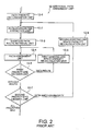
- Fig. 2 is a flow chart showing the operations of the additional path assignment unit 12 of Fig. 1.
- the additional path assignment unit 12 includes a path priority determination unit 12-1, a path-by-priorities extraction unit 12-2, a shortest path route retrieval unit 12-3, a path assignment unit 12-4, a first priority end decision unit 12-5 and a first existing link space capacity re-calculation unit 12-6.
- the path priority determination unit 12-1 determines the priorities to all additional paths according to the path transmission rates as the path attributes thereby to re-arrange the additional paths in the order from the higher to lower priorities.
- the path-by-priorities extraction unit 12-2 compiles and extracts the paths of the same priority in the order from the higher priorities.
- the shortest path route retrieval unit 12-3 extracts a transmission link capable of assigning the paths, as extracted by the path-by-priorities extraction unit 12-2, to the space portions.
- the shortest path route retrieval unit 12-3 compiles the extracted paths separately of sending/addressed stations, and determines the shortest path utilizing the space portion of the transmission link for the compiled paths.
- the pass assignment unit 12-4 assigns such ones of the paths extracted by the path-by-priorities extraction unit 12-2 as have their routes found by the shortest path route retrieval unit 12-3, while being compiled in the number to be assigned for the paths of all the priorities in the order from the higher priority, to the routes.
- the paths are re-arranged in the order of the shorter total path length, where the order of the less transmission links to be passed is the same.
- the first priority end decision unit 12-5 examines whether or not there is a path of a next priority, if there is an unused space portion of the transmission link.
- the first existing link space capacity re-calculation unit 12-6 calculates transmission link unused space information if there is left the path of the next priority, and the routine returns to the path assignment unit 12-4. The operations thus far described are repeated till the end of all the priorities by a second priority end decision unit 12-7 and a second existing link space capacity re-calculation unit 12-8.
- JP-A Japanese Unexamined Patent Publications
- the route design system thus constructed is troubled by a problem that the design takes a long time, because the operation of the first existing link space capacity re-calculation unit 12-6 is performed each time the demand is received.
- the method of solving that problem is disclosed in none of the foregoing Publications.
- an object of the invention is to provide a route design system and a route design method which is capable of realizing a high-speed accommodation design.
- the present invention provides a route design system among nodes from at least one of starting node through a plurality of relay nodes to a terminal node.
- This route design system comprises: a route candidate design unit for designing a plurality of different route candidates from the starting node to the terminal node; and an accommodation unit for accommodating a demand in a predetermined one of the routes designed by the route candidate design unit, according to a predetermined procedure.
- a route design method designs nodes from at least one of starting node through a plurality of relay nodes to a terminal node.
- This route design method comprises: a route candidate design step for designing a plurality of different route candidates from the starting node to the terminal node; and an accommodation step for accommodating a demand in a predetermined one of the routes designed by the route candidate design step, according to a predetermined procedure.
- the present invention contemplates to provide a communication network route design system for making a high-speed accommodation design possible.
- a route candidate design unit 31 designs route candidates among nodes, and assigns available bands for the individual route candidates.
- the route candidate design unit 31 also arrays the individual route candidates in the order of priorities.
- a primary accommodation design unit 33 tries accommodation of a demand in a route candidate of a first priority. Where the route candidate of the first priority has a sufficient space band, the design is ended by accommodating the demand in the first priority route candidate. Where the space band is not sufficient, a secondary accommodation design unit 34 tries to accommodate the demand in a route of a second priority. On the other hand, the next and later route candidates to be utilized in the primary accommodation design unit 33 are switched to the second priority route. Thus, the chance to complete the design by the time of the primary accommodation design is increased to make the high-speed accommodation design possible.
- Fig. 4 is a structure diagram of one example of the communication network to which the present invention is applied.
- the communication network is constructed to include starting modes S1 and S2, relay nodes T1, T2 and T3, and a terminal node D.
- the starting node S1 and the relay node T1 are connected via a transmission line 41, and the starting node S2 and the relay node T2 are connected via a transmission line 42.
- the relay nodes T1 and T2 are connected via a transmission line 43, and the relay nodes T1 and T3 are connected via a transmission line 44.
- the relay nodes T2 and T3 are connected via a transmission line 45, and the relay node T3 and the terminal node D are connected via a transmission line 46.
- Fig. 3 is a flow chart for explaining the structure of the route design system.
- the route design system is constructed to include a route candidate design unit 31, a demand decision unit 32, the primary accommodation design unit 33, the secondary accommodation design unit 34 and an accommodation release unit 35.
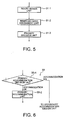
- Fig. 5 is a flow chart for explaining the functions of the route candidate design unit 31 of Fig. 3.
- a route design unit 31-1 designs a plurality of routes between two arbitrary nodes.
- a reserved band assignment unit 31-2 assigns a band, which can be utilized in a plurality of designed routes, as a reserved band.
- a priority decision unit 31-3 calculates the priorities of all the designed routes. The priorities are determined from a total hop number of routes and the size of the reserved band, and route candidates are nominated in the order of the routes of higher priorities.
- the total hop number is the sum of the transmission lines shown in Fig. 4. For example, the total hop number from the starting node S1 via the relay nodes T2 and T3 to the terminal node D is 3.
- Fig. 6 is a flow chart for explaining a routine at the primary accommodation design unit 33 of Fig. 3.
- the procedure at the primary accommodation design unit 33 is executed if it is decided at the demand decision unit 32 of Fig. 3 that the demand is an accommodation demand.
- a primary accommodation decision unit 33-1 inspects a sending node and an addressed node of the demand received, and retrieves the route candidate of the first priority between the nodes designed by the route candidate design unit 31.
- the primary accommodation decision unit 33-1 decides an accommodation OK, if a space band more than that demanded by the demand is in the route candidate of the first priority.
- a primary accommodation unit 33-2 selects an accommodation route of the demand as the route candidate of the first priority, and subtracts the band demanded by the accommodated demand, from the space band of the route candidate of the first priority.
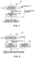
- Fig. 7 is a flow chart for explaining the secondary accommodation design unit 34 of Fig. 3.
- a secondary accommodation decision unit 34-1 decides it in the order of route candidates of a second priority whether or not there is a space band more than the band demanded by the demand.
- the secondary accommodation decision unit 34-1 decides the accommodation OK if it finds a route candidate having a sufficient space band.
- a secondary accommodation unit 34-2 selects the route candidate decided to be the accommodation OK, as the accommodation route of the demand, and subtracts the band demanded by the accommodated demand, from the space band of that route candidate.
- the secondary accommodation unit 34-2 exchanges the route candidate of the first priority, as used in the primary accommodation design unit 33, for the route accommodated here.
- Fig. 8 is a flow chart for explaining the accommodation release unit 35 of Fig. 3.
- an accommodation route decision unit 35-1 decides whether or not the demand accommodated in the route candidate of the first priority is released. If the demand accommodated in the route candidate of the first priority is released, a primary accommodation release unit 35-2 adds the band of the demand to be released, to the space band of the route candidate of the first priority.
- a secondary accommodation release unit 35-3 retrieves the route candidate in which the demand demanded to be released is accommodated, and adds the band of the demand to be released, to the space band of the retrieved route candidate.
- the route design unit 31-1 designs routes R1 and R2 from the starting node S1 to the terminal node D and routes R3 and R4 from the starting node S2 to the terminal node D, respectively, in the following manners.
- the reserved band assignment unit 31-2 assigns the reserved bands to the individual routes R1 to R4. If the band of all links between the individual links is 60 MBytes/sec and is equivalently assigned, the band to be assigned to the individual routes is 15 MBytes/sec.
- the priority decision unit 31-3 executes the priority decision between the routes R1 and R2 from the starting node S1 to the terminal node and the priority decision between the routes R3 and R4 from the starting node S2 to the terminal node D. If the route having the smaller total hop number is made prior, the routes R1 and R4 are the first priority ones.
- the routine transfers to the primary accommodation design unit 33.
- the primary accommodation decision unit 33-1 retrieves the route candidate R1 of the first priority from the starting node S1 to the terminal node D.
- the route candidate R1 of the first priority does not accommodate any demand yet so that it has a space band of 15 MBytes/sec.
- the primary accommodation decision unit 33-1 decides that the demand d1 of 10 MBytes/sec is the accommodation OK.
- the routine advances like the accommodation demand d1 from the demand decision unit 32 to the primary accommodation decision unit 33-1.
- the accommodation demand d2 of 10 MBytes/sec is received although the space band of the route candidate R1 of the first priority is only 5 MBytes/sec, so that the primary accommodation decision unit 33-1 decides the accommodation NG, and the routine advances to the secondary accommodation design unit 34.
- the secondary accommodation decision unit 34-1 retrieves the route of the second priority from the starting node S1 to the terminal node D, the route candidate R2 is found.
- This route candidate R2 does not accommodate any demand yet, so that it has a space band of 15 MBytes/sec.
- the routine advances from the demand decision unit 32 to the accommodation release unit 35.
- the accommodation route decision unit 35-1 retrieves the accommodation route of the demand d1. If it is found that the accommodation route R1 of the demand d1 is not the route candidate of the first priority, the routine advances to the second accommodation release unit 35-3.
- the route design system of the first embodiment it is possible to shorten the design time period and to increase the number of demands to be processed for a unit time period. This is because the design is divided into primary and secondary ones thereby to increase the chances of completing the design only by the primary design of no route retrieval.
- the band of the link is wholly distributed to the route candidates,
- a preliminary band is retained, and the remainder is distributed among the route candidates.
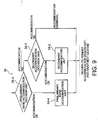
- Fig. 9 is a flow chart for explaining the secondary accommodation design unit 34 in the second embodiment.
- the preliminary band is handled as the band which can be utilized by any of the route candidates R1 to R4.
- a preliminary band accommodation decision unit 34-3 it is decided whether or not the demand, as could not be accommodated in the primary accommodation design unit 33, can be accommodated by using the space band of the route candidate of the first priority and the preliminary band. If the accommodation OK, the routine advances to a preliminary band accommodation unit 34-4. in this preliminary band accommodation unit 34-4, the accommodation route of the demand is selected as the first priority route, and the space band of the route candidate of the first priority and the space bands of the preliminary bands of all the links on the route candidate of the first priority are updated. If the accommodation NG is decided by the preliminary band accommodation decision unit 34-3, on the other hand, the routine advances to the secondary accommodation decision unit 34-1. The subsequent operations are similar to those of the first embodiment having been described.
- Fig. 10 is a flow chart for explaining the accommodation release unit 35 in the second embodiment.
- a preliminary accommodation release unit 35-4 updates the space band of the route candidate of the first priority and the space bands of the preliminary bands of all the links on the route candidate of the first priority are updated.
- a reserved band of 10 MBytes/sec is assigned to each of the route candidates R1 to R4, if the preliminary band of 20 MBytes/sec is assigned to each link whereas the remainder of 40 MBytes/sec is equivalently assigned to the route candidates.
- the demand d1 of the band of 5 MBytes/sec is received from the starting node S1 to the terminal node D, the demand d1 is accommodated like the first embodiment by the route candidate R1 of the first priority.
- the demand d2 of a band of 10 MBytes/sec is subsequently accommodated from the starting node S1 to the terminal node D, the demand d2 cannot be accommodated by the space band of the route candidate R1 of the first priority.
- the routine advances to the secondary accommodation design unit 34 of Fig. 9.
- the space bands of the preliminary bands of the link on the route candidate R1 of the first priority and the links between the starting node S1 - the relay node T1, between the relay nodes T1 - T3 and between the relay node T3 - the terminal node D are examined at first at the preliminary band accommodation decision unit 34-3.
- all the space bands are 20 MBytes/sec, and it is decided that the demand d2 can be accommodated.
- the routine advances to the preliminary band accommodation unit 34-4.
- the space band of the route candidate R1 of the first priority accommodates 5 MBytes/sec to reduce the space band to 0 MBytes/sec.
- the space bands of the preliminary bands of the link on the route candidate R1 of the first priority and the links between the starting node S1 - the relay node T1, between the relay nodes T1 - T3 and between the relay node T3 - the terminal node D are reduced by the band which could not be accommodated in the route candidate R1 of the first priority.
- the accommodation route decision unit 35-1 of Fig. 10 it is decided that the demand d2 is accommodated by using the route candidate of the first priority and the preliminary band, and the routine advances to the preliminary accommodation release unit 35-4.
- 5 MBytes/sec, as accommodated in the route candidate R1 of the first priority, of the band of the demand d2 is returned to the space band of the route candidate R1 of the first priority, to set the space band to 5 MBytes/sec.
- this preliminary band can be flexibly shared among the bands of the route candidates for accommodating the demands.
- the present invention provides a route design system among nodes from a starting node through at least one relay node to a terminal node.
- This route design system comprises: a route candidate design unit for designing a plurality of different route candidates from the starting node to the terminal node; and an accommodation unit for accommodating a demand in a predetermined one of the routes designed by the route candidate design unit, according to a predetermined procedure.
- the route design system is constructed by designing the plurality of different route candidates in advance and by accommodating the demand in the order from the route of the highest priority. Therefore, the trouble of retrieving the route candidate in each response to the demand, so that a high-speed accommodation can be designed.
Landscapes
- Engineering & Computer Science (AREA)
- Computer Networks & Wireless Communication (AREA)
- Signal Processing (AREA)
- Data Exchanges In Wide-Area Networks (AREA)
- Telephonic Communication Services (AREA)
- Feedback Control In General (AREA)
- Traffic Control Systems (AREA)
- Navigation (AREA)
Abstract
Description
- R1:
- S1 - T1 - T3 - D;
- R2:
- S1 - T1 - T2 - T3 - D;
- R3:
- S2 - T2 - T1 - T3 - D; and
- R4:
- S2 - T2 - T3 - D.
Claims (12)
- A route design system among nodes from at least one of starting node (S1, S2) through a plurality of relay nodes (T1, T2, T3) to a terminal node (D), which is characterized in that said system comprises:route candidate design means (31) for designing a plurality of different route candidates from said at least one of starting node to said terminal node; andaccommodation means (32,33,34) for accommodating a demand in a predetermined one of the routes designed by said route candidate design means, according to a predetermined procedure.
- A route design system according to Claim 1,wherein said route candidate design means includes: a band assignment unit (31-2) for assigning bands available in the individual route candidates to said plurality of different route candidates; and a priority ordering unit (31-3) for ordering the priorities of said individual route candidates, andwherein said accommodation means includes a decision unit (32, 33) for deciding whether or not the route of the first priority has a space band no more than the band demanded by said route of the first priority, whereby said demand is accommodated in said route of the first priority if said decision unit decides that said space band is had.
- A route design system according to Claim 2,
wherein said accommodation means accommodates said demand in the route of a second priority, if said decision unit decides that said space band is not had. - A route design system according to Claim 3,
wherein said accommodation means further includes an exchange unit (34-2) for exchanging said route of the first priority and said route of the second priority after said demand was accommodated in said route of the second priority. - A route design system according to Claim 1,2,3, or 4,wherein said route candidate design means includes: a band assignment unit (31-2) for assigning, after a preliminary band was retained, the remaining bands to said plurality of different route candidates; and a priority ordering unit (31-3) for ordering the priorities of said individual route candidates, andwherein said accommodation means includes a decision unit (32, 33) for deciding whether or not the route of the first priority has a space band no more than the band demanded by said route of the first priority, whereby said demand is accommodated in said route of the first priority if said decision unit decides that said space band is had.
- A route design system according to Claim 5,
wherein said accommodation means accommodates said demand by using the space band of said route of the first priority and said preliminary band, if said decision unit decides that said space band is not had and if the total of the space band of said route of the first priority and said preliminary band is no less than the band demanded by said demand. - A route design method among nodes from at least one of starting node (S1, S2) through a plurality of relay nodes (T1, T2, T3) to a terminal node (D), which is characterized in that said method comprises:a route candidate design step (31) for designing a plurality of different route candidates from said starting node to said terminal node; andan accommodation step (32, 33, 34) for accommodating a demand in a predetermined one of the routes designed by said route candidate design step, according to a predetermined procedure.
- A route design method according to Claim 7,wherein said route candidate design step includes: a band assignment step (31-2) for assigning bands available in the individual route candidates to said plurality of different route candidates; and a priority ordering step (31-3) for ordering the priorities of said individual route candidates, andwherein said accommodation step includes a decision step (32, 33) for deciding whether or not the route of the first priority has a space band no more than the band demanded by said route of the first priority, whereby said demand is accommodated in said route of the first priority if said decision step decides that said space band is had.
- A route design method according to Claim 8,
wherein said accommodation step accommodates said demand in the route of a second priority, if said decision step decides that said space band is not had. - A route design method according to Claim 9,
wherein said accommodation step further includes an exchange step (34-2) for exchanging said route of the first priority and said route of the second priority after said demand was accommodated in said route of the second priority. - A route design method according to Claim 7, 8,9 or 10,wherein said route candidate design step includes: a band assignment step (31-2) for assigning, after a preliminary band was retained, the remaining bands to said plurality of different route candidates; and a priority ordering step (31-3) for ordering the priorities of said individual route candidates, andwherein said accommodation step includes a decision step (32, 33) for deciding whether or not the route of the first priority has a space band no more than the band demanded by said route of the first priority, whereby said demand is accommodated in said route of the first priority if said decision step decides that said space band is had.
- A route design method according to Claim 11,
wherein said accommodation step accommodates said demand by using the space band of said route of the first priority and said preliminary band, if said decision step decides that said space band is not had and if the total of the space band of said route of the first priority and said preliminary band is no less than the band demanded by said demand.
Applications Claiming Priority (2)
| Application Number | Priority Date | Filing Date | Title |
|---|---|---|---|
| JP2000031345A JP2001223744A (en) | 2000-02-09 | 2000-02-09 | Route design system and route design method |
| JP2000031345 | 2000-02-09 |
Publications (2)
| Publication Number | Publication Date |
|---|---|
| EP1126658A2 true EP1126658A2 (en) | 2001-08-22 |
| EP1126658A3 EP1126658A3 (en) | 2003-09-17 |
Family
ID=18556112
Family Applications (1)
| Application Number | Title | Priority Date | Filing Date |
|---|---|---|---|
| EP20010102781 Withdrawn EP1126658A3 (en) | 2000-02-09 | 2001-02-08 | Route design system and route design method capable of realizing high-speed accomodation design |
Country Status (5)
| Country | Link |
|---|---|
| US (1) | US20010030945A1 (en) |
| EP (1) | EP1126658A3 (en) |
| JP (1) | JP2001223744A (en) |
| CN (1) | CN1309489A (en) |
| HK (1) | HK1039701A1 (en) |
Families Citing this family (10)
| Publication number | Priority date | Publication date | Assignee | Title |
|---|---|---|---|---|
| CN1518325B (en) * | 2003-01-17 | 2010-04-28 | 华为技术有限公司 | A Method for Dynamically Adjusting Routing Priority in IP Telephony System |
| JP5071165B2 (en) * | 2007-03-19 | 2012-11-14 | 日本電気株式会社 | Route multiplexing communication system, communication node, and communication method |
| US8509075B2 (en) * | 2007-03-23 | 2013-08-13 | Hewlett-Packard Development Company, Lp | Data-type-based network path configuration |
| US8089882B2 (en) * | 2007-03-23 | 2012-01-03 | Hewlett-Packard Development Company, L.P. | Load-aware network path configuration |
| CN101068214B (en) * | 2007-06-26 | 2013-01-30 | 华为技术有限公司 | Route convergent method and equipment |
| JP5605728B2 (en) * | 2010-10-22 | 2014-10-15 | 株式会社エヴリカ | Information processing apparatus, communication method, and communication program |
| US20130094397A1 (en) * | 2011-10-15 | 2013-04-18 | Young Jin Kim | Method and apparatus for localized and scalable packet forwarding |
| WO2013161213A1 (en) * | 2012-04-27 | 2013-10-31 | 日本電気株式会社 | Communication system, and communication control method |
| JP6546567B2 (en) * | 2016-08-01 | 2019-07-17 | 日本電信電話株式会社 | Route arrangement apparatus, route arrangement method, and program |
| WO2018047943A1 (en) * | 2016-09-09 | 2018-03-15 | 日本電気株式会社 | Communication system, edge node, communication method and program |
Family Cites Families (12)
| Publication number | Priority date | Publication date | Assignee | Title |
|---|---|---|---|---|
| EP0714192A1 (en) * | 1994-11-24 | 1996-05-29 | International Business Machines Corporation | Method for preempting connections in high speed packet switching networks |
| GB2299729B (en) * | 1995-04-01 | 1999-11-17 | Northern Telecom Ltd | Traffic routing in a telecommunications network |
| US6011804A (en) * | 1995-12-20 | 2000-01-04 | International Business Machines Corporation | Dynamic bandwidth reservation for control traffic in high speed packet switching networks |
| US6011776A (en) * | 1996-06-20 | 2000-01-04 | International Business Machines Corporation | Dynamic bandwidth estimation and adaptation in high speed packet switching networks |
| US5881050A (en) * | 1996-07-23 | 1999-03-09 | International Business Machines Corporation | Method and system for non-disruptively assigning link bandwidth to a user in a high speed digital network |
| US5936940A (en) * | 1996-08-22 | 1999-08-10 | International Business Machines Corporation | Adaptive rate-based congestion control in packet networks |
| US6597684B1 (en) * | 1997-12-24 | 2003-07-22 | Nortel Networks Ltd. | Distributed architecture and associated protocols for efficient quality of service-based route computation |
| US6212169B1 (en) * | 1998-03-13 | 2001-04-03 | Alcatel Canada Inc. | Parameter reconfiguration of connected calls |
| EP1950920A1 (en) * | 1998-04-14 | 2008-07-30 | Corps of Discovery Patent Holding LLC | Method and apparatus for providing guaranteed quality of service in a local or wide area network |
| US6356564B1 (en) * | 1998-04-22 | 2002-03-12 | Alcatel Canada Inc. | Use of booking factors to redefine available bandwidth |
| US6687228B1 (en) * | 1998-11-10 | 2004-02-03 | International Business Machines Corporation | Method and system in a packet switching network for dynamically sharing the bandwidth of a virtual path connection among different types of connections |
| US6657965B1 (en) * | 1998-12-15 | 2003-12-02 | Siemens Information & Communication Networks, Inc. | System and method for enhanced routing and reservation protocol |
-
2000
- 2000-02-09 JP JP2000031345A patent/JP2001223744A/en active Pending
-
2001
- 2001-02-08 EP EP20010102781 patent/EP1126658A3/en not_active Withdrawn
- 2001-02-08 US US09/778,904 patent/US20010030945A1/en not_active Abandoned
- 2001-02-09 CN CN01110851A patent/CN1309489A/en active Pending
-
2002
- 2002-02-07 HK HK02100971.1A patent/HK1039701A1/en unknown
Also Published As
| Publication number | Publication date |
|---|---|
| JP2001223744A (en) | 2001-08-17 |
| HK1039701A1 (en) | 2002-05-03 |
| EP1126658A3 (en) | 2003-09-17 |
| US20010030945A1 (en) | 2001-10-18 |
| CN1309489A (en) | 2001-08-22 |
Similar Documents
| Publication | Publication Date | Title |
|---|---|---|
| US5583860A (en) | Communications network independent designing system and managing method | |
| US5274643A (en) | Method for optimizing a network having virtual circuit routing over virtual paths | |
| Wu et al. | Receiver-initiated busy-tone multiple access in packet radio networks | |
| AU654930B2 (en) | Methods and apparatus for routing packets in packet transmission networks | |
| US5548639A (en) | Distributed control of telecommunication network for setting up an alternative communication path | |
| US5166927A (en) | Adaptive pathfinding neutral network for a packet communication system | |
| JP4433624B2 (en) | Communication network, centralized control device, communication node device, and status notification information mutual exchange method used therefor | |
| EP0343611B1 (en) | Routing method for fast packet switching systems | |
| EP0524350B1 (en) | Telecommunication system for transmitting cells through switching nodes interconnected by groups of transmission links | |
| EP1126658A2 (en) | Route design system and route design method capable of realizing high-speed accomodation design | |
| EP2268055A2 (en) | Optical switch and protocols for use therewith | |
| CA2224574A1 (en) | Knowledge based path set up and spare capacity assignment for distributed network restoration | |
| US5029165A (en) | Method of allotting links and routing messages for a common channel type signalling transfer point | |
| EP0411815B1 (en) | High-speed packet data network using serially connected packet and circuit switches | |
| EP0820165B1 (en) | System for transmission between base station and exchange of mobile communication using fixed-length cell | |
| EP0457620B1 (en) | Chordal ring network | |
| US20040001670A1 (en) | High capacity optical node | |
| CA2426386A1 (en) | Scaleable interconnect structure utilizing quality-of-service handling | |
| US5844981A (en) | Method and system of improved routing to WATS | |
| EP0939576B1 (en) | Circuit-switched network | |
| JP2003264518A (en) | Time division and wavelength division multiplexing optical switching nodes | |
| US7283552B2 (en) | Method of scheduling bursts of data for transmission in a communication network | |
| US8000250B1 (en) | Method for routing optical signals with diversity requirements | |
| KR102590563B1 (en) | Method for searching transmission path and slot for end-to-end periodic low-delay traffic transmission based on offset and control device performing the same | |
| WO2001086862A2 (en) | Method and system for providing a protection path for connectionless signals in a telecommunications network |
Legal Events
| Date | Code | Title | Description |
|---|---|---|---|
| PUAI | Public reference made under article 153(3) epc to a published international application that has entered the european phase |
Free format text: ORIGINAL CODE: 0009012 |
|
| AK | Designated contracting states |
Kind code of ref document: A2 Designated state(s): AT BE CH CY DE DK ES FI FR GB GR IE IT LI LU MC NL PT SE TR |
|
| AX | Request for extension of the european patent |
Free format text: AL;LT;LV;MK;RO;SI |
|
| PUAL | Search report despatched |
Free format text: ORIGINAL CODE: 0009013 |
|
| AK | Designated contracting states |
Kind code of ref document: A3 Designated state(s): AT BE CH CY DE DK ES FI FR GB GR IE IT LI LU MC NL PT SE TR |
|
| AX | Request for extension of the european patent |
Extension state: AL LT LV MK RO SI |
|
| 17P | Request for examination filed |
Effective date: 20030807 |
|
| AKX | Designation fees paid |
Designated state(s): DE ES FR GB IT |
|
| STAA | Information on the status of an ep patent application or granted ep patent |
Free format text: STATUS: THE APPLICATION IS DEEMED TO BE WITHDRAWN |
|
| 18D | Application deemed to be withdrawn |
Effective date: 20061018 |