EP1126225A1 - Cryogenic reflux condenser system for producing oxygen-enriched air - Google Patents
Cryogenic reflux condenser system for producing oxygen-enriched air Download PDFInfo
- Publication number
- EP1126225A1 EP1126225A1 EP01103770A EP01103770A EP1126225A1 EP 1126225 A1 EP1126225 A1 EP 1126225A1 EP 01103770 A EP01103770 A EP 01103770A EP 01103770 A EP01103770 A EP 01103770A EP 1126225 A1 EP1126225 A1 EP 1126225A1
- Authority
- EP
- European Patent Office
- Prior art keywords
- feed air
- reflux condenser
- regenerators
- passing
- heat exchanger
- Prior art date
- Legal status (The legal status is an assumption and is not a legal conclusion. Google has not performed a legal analysis and makes no representation as to the accuracy of the status listed.)
- Withdrawn
Links
- 238000010992 reflux Methods 0.000 title claims abstract description 42
- QVGXLLKOCUKJST-UHFFFAOYSA-N atomic oxygen Chemical compound [O] QVGXLLKOCUKJST-UHFFFAOYSA-N 0.000 title claims description 23
- 239000001301 oxygen Substances 0.000 title claims description 23
- 229910052760 oxygen Inorganic materials 0.000 title claims description 23
- 230000008016 vaporization Effects 0.000 claims description 27
- 239000007788 liquid Substances 0.000 claims description 24
- IJGRMHOSHXDMSA-UHFFFAOYSA-N Atomic nitrogen Chemical compound N#N IJGRMHOSHXDMSA-UHFFFAOYSA-N 0.000 claims description 18
- 239000012530 fluid Substances 0.000 claims description 14
- 239000012535 impurity Substances 0.000 claims description 11
- 238000009835 boiling Methods 0.000 claims description 9
- 229910052757 nitrogen Inorganic materials 0.000 claims description 9
- 238000000034 method Methods 0.000 claims description 7
- 238000004519 manufacturing process Methods 0.000 claims description 4
- 239000002699 waste material Substances 0.000 abstract description 3
- 238000000926 separation method Methods 0.000 abstract description 2
- 239000003570 air Substances 0.000 description 72
- 238000005057 refrigeration Methods 0.000 description 6
- CURLTUGMZLYLDI-UHFFFAOYSA-N Carbon dioxide Chemical compound O=C=O CURLTUGMZLYLDI-UHFFFAOYSA-N 0.000 description 4
- 239000007789 gas Substances 0.000 description 3
- 229910002092 carbon dioxide Inorganic materials 0.000 description 2
- 239000001569 carbon dioxide Substances 0.000 description 2
- XLYOFNOQVPJJNP-UHFFFAOYSA-N water Chemical compound O XLYOFNOQVPJJNP-UHFFFAOYSA-N 0.000 description 2
- 239000012080 ambient air Substances 0.000 description 1
- 230000015572 biosynthetic process Effects 0.000 description 1
- 230000006835 compression Effects 0.000 description 1
- 238000007906 compression Methods 0.000 description 1
- 238000009833 condensation Methods 0.000 description 1
- 230000005494 condensation Effects 0.000 description 1
- 238000001816 cooling Methods 0.000 description 1
- 238000004821 distillation Methods 0.000 description 1
- 238000001035 drying Methods 0.000 description 1
- 230000000694 effects Effects 0.000 description 1
- 239000000463 material Substances 0.000 description 1
- 239000000203 mixture Substances 0.000 description 1
- 230000003647 oxidation Effects 0.000 description 1
- 238000007254 oxidation reaction Methods 0.000 description 1
- 238000012856 packing Methods 0.000 description 1
- 230000000737 periodic effect Effects 0.000 description 1
- 238000011084 recovery Methods 0.000 description 1
- 230000002441 reversible effect Effects 0.000 description 1
- 230000000630 rising effect Effects 0.000 description 1
- 239000000126 substance Substances 0.000 description 1
Images

Classifications
-
- F—MECHANICAL ENGINEERING; LIGHTING; HEATING; WEAPONS; BLASTING
- F25—REFRIGERATION OR COOLING; COMBINED HEATING AND REFRIGERATION SYSTEMS; HEAT PUMP SYSTEMS; MANUFACTURE OR STORAGE OF ICE; LIQUEFACTION SOLIDIFICATION OF GASES
- F25J—LIQUEFACTION, SOLIDIFICATION OR SEPARATION OF GASES OR GASEOUS OR LIQUEFIED GASEOUS MIXTURES BY PRESSURE AND COLD TREATMENT OR BY BRINGING THEM INTO THE SUPERCRITICAL STATE
- F25J3/00—Processes or apparatus for separating the constituents of gaseous or liquefied gaseous mixtures involving the use of liquefaction or solidification
- F25J3/02—Processes or apparatus for separating the constituents of gaseous or liquefied gaseous mixtures involving the use of liquefaction or solidification by rectification, i.e. by continuous interchange of heat and material between a vapour stream and a liquid stream
- F25J3/04—Processes or apparatus for separating the constituents of gaseous or liquefied gaseous mixtures involving the use of liquefaction or solidification by rectification, i.e. by continuous interchange of heat and material between a vapour stream and a liquid stream for air
-
- F—MECHANICAL ENGINEERING; LIGHTING; HEATING; WEAPONS; BLASTING
- F25—REFRIGERATION OR COOLING; COMBINED HEATING AND REFRIGERATION SYSTEMS; HEAT PUMP SYSTEMS; MANUFACTURE OR STORAGE OF ICE; LIQUEFACTION SOLIDIFICATION OF GASES
- F25J—LIQUEFACTION, SOLIDIFICATION OR SEPARATION OF GASES OR GASEOUS OR LIQUEFIED GASEOUS MIXTURES BY PRESSURE AND COLD TREATMENT OR BY BRINGING THEM INTO THE SUPERCRITICAL STATE
- F25J3/00—Processes or apparatus for separating the constituents of gaseous or liquefied gaseous mixtures involving the use of liquefaction or solidification
- F25J3/02—Processes or apparatus for separating the constituents of gaseous or liquefied gaseous mixtures involving the use of liquefaction or solidification by rectification, i.e. by continuous interchange of heat and material between a vapour stream and a liquid stream
- F25J3/04—Processes or apparatus for separating the constituents of gaseous or liquefied gaseous mixtures involving the use of liquefaction or solidification by rectification, i.e. by continuous interchange of heat and material between a vapour stream and a liquid stream for air
- F25J3/04248—Generation of cold for compensating heat leaks or liquid production, e.g. by Joule-Thompson expansion
- F25J3/04284—Generation of cold for compensating heat leaks or liquid production, e.g. by Joule-Thompson expansion using internal refrigeration by open-loop gas work expansion, e.g. of intermediate or oxygen enriched (waste-)streams
- F25J3/0429—Generation of cold for compensating heat leaks or liquid production, e.g. by Joule-Thompson expansion using internal refrigeration by open-loop gas work expansion, e.g. of intermediate or oxygen enriched (waste-)streams of feed air, e.g. used as waste or product air or expanded into an auxiliary column
- F25J3/04296—Claude expansion, i.e. expanded into the main or high pressure column
-
- F—MECHANICAL ENGINEERING; LIGHTING; HEATING; WEAPONS; BLASTING
- F25—REFRIGERATION OR COOLING; COMBINED HEATING AND REFRIGERATION SYSTEMS; HEAT PUMP SYSTEMS; MANUFACTURE OR STORAGE OF ICE; LIQUEFACTION SOLIDIFICATION OF GASES
- F25J—LIQUEFACTION, SOLIDIFICATION OR SEPARATION OF GASES OR GASEOUS OR LIQUEFIED GASEOUS MIXTURES BY PRESSURE AND COLD TREATMENT OR BY BRINGING THEM INTO THE SUPERCRITICAL STATE
- F25J3/00—Processes or apparatus for separating the constituents of gaseous or liquefied gaseous mixtures involving the use of liquefaction or solidification
- F25J3/02—Processes or apparatus for separating the constituents of gaseous or liquefied gaseous mixtures involving the use of liquefaction or solidification by rectification, i.e. by continuous interchange of heat and material between a vapour stream and a liquid stream
- F25J3/04—Processes or apparatus for separating the constituents of gaseous or liquefied gaseous mixtures involving the use of liquefaction or solidification by rectification, i.e. by continuous interchange of heat and material between a vapour stream and a liquid stream for air
- F25J3/04248—Generation of cold for compensating heat leaks or liquid production, e.g. by Joule-Thompson expansion
- F25J3/04284—Generation of cold for compensating heat leaks or liquid production, e.g. by Joule-Thompson expansion using internal refrigeration by open-loop gas work expansion, e.g. of intermediate or oxygen enriched (waste-)streams
- F25J3/04309—Generation of cold for compensating heat leaks or liquid production, e.g. by Joule-Thompson expansion using internal refrigeration by open-loop gas work expansion, e.g. of intermediate or oxygen enriched (waste-)streams of nitrogen
-
- F—MECHANICAL ENGINEERING; LIGHTING; HEATING; WEAPONS; BLASTING
- F25—REFRIGERATION OR COOLING; COMBINED HEATING AND REFRIGERATION SYSTEMS; HEAT PUMP SYSTEMS; MANUFACTURE OR STORAGE OF ICE; LIQUEFACTION SOLIDIFICATION OF GASES
- F25J—LIQUEFACTION, SOLIDIFICATION OR SEPARATION OF GASES OR GASEOUS OR LIQUEFIED GASEOUS MIXTURES BY PRESSURE AND COLD TREATMENT OR BY BRINGING THEM INTO THE SUPERCRITICAL STATE
- F25J3/00—Processes or apparatus for separating the constituents of gaseous or liquefied gaseous mixtures involving the use of liquefaction or solidification
- F25J3/02—Processes or apparatus for separating the constituents of gaseous or liquefied gaseous mixtures involving the use of liquefaction or solidification by rectification, i.e. by continuous interchange of heat and material between a vapour stream and a liquid stream
- F25J3/04—Processes or apparatus for separating the constituents of gaseous or liquefied gaseous mixtures involving the use of liquefaction or solidification by rectification, i.e. by continuous interchange of heat and material between a vapour stream and a liquid stream for air
- F25J3/04624—Processes or apparatus for separating the constituents of gaseous or liquefied gaseous mixtures involving the use of liquefaction or solidification by rectification, i.e. by continuous interchange of heat and material between a vapour stream and a liquid stream for air using integrated mass and heat exchange, so-called non-adiabatic rectification, e.g. dephlegmator, reflux exchanger
- F25J3/0463—Simultaneously between rectifying and stripping sections, i.e. double dephlegmator
-
- F—MECHANICAL ENGINEERING; LIGHTING; HEATING; WEAPONS; BLASTING
- F25—REFRIGERATION OR COOLING; COMBINED HEATING AND REFRIGERATION SYSTEMS; HEAT PUMP SYSTEMS; MANUFACTURE OR STORAGE OF ICE; LIQUEFACTION SOLIDIFICATION OF GASES
- F25J—LIQUEFACTION, SOLIDIFICATION OR SEPARATION OF GASES OR GASEOUS OR LIQUEFIED GASEOUS MIXTURES BY PRESSURE AND COLD TREATMENT OR BY BRINGING THEM INTO THE SUPERCRITICAL STATE
- F25J2200/00—Processes or apparatus using separation by rectification
- F25J2200/04—Processes or apparatus using separation by rectification in a dual pressure main column system
-
- F—MECHANICAL ENGINEERING; LIGHTING; HEATING; WEAPONS; BLASTING
- F25—REFRIGERATION OR COOLING; COMBINED HEATING AND REFRIGERATION SYSTEMS; HEAT PUMP SYSTEMS; MANUFACTURE OR STORAGE OF ICE; LIQUEFACTION SOLIDIFICATION OF GASES
- F25J—LIQUEFACTION, SOLIDIFICATION OR SEPARATION OF GASES OR GASEOUS OR LIQUEFIED GASEOUS MIXTURES BY PRESSURE AND COLD TREATMENT OR BY BRINGING THEM INTO THE SUPERCRITICAL STATE
- F25J2205/00—Processes or apparatus using other separation and/or other processing means
- F25J2205/24—Processes or apparatus using other separation and/or other processing means using regenerators, cold accumulators or reversible heat exchangers
-
- F—MECHANICAL ENGINEERING; LIGHTING; HEATING; WEAPONS; BLASTING
- F25—REFRIGERATION OR COOLING; COMBINED HEATING AND REFRIGERATION SYSTEMS; HEAT PUMP SYSTEMS; MANUFACTURE OR STORAGE OF ICE; LIQUEFACTION SOLIDIFICATION OF GASES
- F25J—LIQUEFACTION, SOLIDIFICATION OR SEPARATION OF GASES OR GASEOUS OR LIQUEFIED GASEOUS MIXTURES BY PRESSURE AND COLD TREATMENT OR BY BRINGING THEM INTO THE SUPERCRITICAL STATE
- F25J2245/00—Processes or apparatus involving steps for recycling of process streams
- F25J2245/50—Processes or apparatus involving steps for recycling of process streams the recycled stream being oxygen
Definitions
- This invention relates generally to air separation for the production of lower purity products wherein a column is not employed.
- Oxygen-enriched air is widely used in a number of applications such as in furnace operations and chemical oxidation processes. While lower purity oxygen may be produced with a system using distillation columns, such systems are generally not economical for producing oxygen-enriched air. Oxygen-enriched air may be produced with a system employing reflux condensers, and it is desirable to produce oxygen-enriched air with a reflux condenser system with improved efficiency over known such systems.
- a method for producing oxygen-enriched air comprising:
- Another aspect of the invention is:
- Apparatus for producing oxygen-enriched air comprising:
- feed air means a mixture comprising primarily nitrogen and oxygen, such as ambient air.
- turboexpansion and “turboexpander” mean respectively method and apparatus for the flow of high pressure gas through a turbine to reduce the pressure and the temperature of the gas.
- directly heat exchange means the bringing of two fluids into heat exchange relation without any physical contact or intermixing of the fluids with each other.
- the term "regenerator” means a reversible periodic heat exchanger through which gases flow in an alternating fashion and in which heat in transit is temporarily stored in a packing material of high thermal capacity.
- the term "reflux condenser” means a heat exchange device containing a plurality of vertically oriented finned tubes or passages for the flow of vapor from the bottom to the top of the tubes or passages, collectively termed the condensing side of the reflux condenser, and a plurality of vertically oriented finned tubes or passages for the flow of liquid from the top to the bottom of the tubes or passages, collectively termed the vaporizing side of the reflux condenser.
- Each condensing tube or passage is in heat exchange relationship with at least one vaporizing tube or passage such that the vapor rising through the condensing tubes or passages is partially condensed by indirect heat exchange with the liquid flowing down the vaporizing tubes or passages which is partially vaporized.
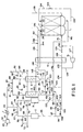
- Figure 1 is a schematic representation of one preferred embodiment of the invention wherein feed air turboexpansion is employed to provide the requisite cryogenic temperatures.
- Figure 2 is a schematic representation of another preferred embodiment of the invention wherein waste fluid turboexpansion is employed to provide the requisite cryogenic temperatures.
- feed air 60 is compressed to a pressure generally within the range of from 45 to 70 pounds per square inch absolute (psia) by passage through compressor 30.
- Resulting compressed feed air 61 is cooled of the heat of compression by passage through aftercooler 1, and the resulting feed air 62 is divided into a first portion 64 comprising from 25 to 45 percent, preferably from 30 to 40 percent, of feed air 62, and into second portion 63 comprising from 55 to 75 percent, preferably from 60 to 70 percent, of feed air 62.
- First feed air portion 64 is passed through one of at least two first regenerators which in the embodiment of the invention illustrated in Figure 1 are regenerators 2 and 3, and second feed air portion 63 is passed through one of at least two second regenerators which in the embodiment of the invention illustrated in Figure 1 are regenerators 4 and 5.
- regenerators 2 and 4 While the return streams are passing through regenerators 3 and 5, with the understanding that these flows are periodically changed so that the feed air passes through regenerators 3 and 5 while the return streams pass through regenerators 2 and 4.
- first feed air portion 64 is passed in piping 65 through valve 66 and piping 67 and 68 to first regenerator 2.
- first feed air portion 64 would be passed in piping 73 through valve 74 and through piping 75 and 76 into first regenerator 3.
- the first feed air portion is cooled and cleaned of high boiling impurities such as carbon dioxide and water vapor which condense and plate out on the internals of the first regenerator. Cooled, cleaned feed air first portion 95 is then passed through piping 96, valve 108 and piping 107 to form feed air stream 109.
- cooled, cleaned feed air first portion 100 would be passed through piping 104, valve 105 and piping 106 to form feed air stream 109.
- Second feed air portion 63 is passed in piping 21 through valve 81 and piping 82 and 84 to second regenerator 4.
- second feed air portion 63 would be passed in piping 86 through valve 87 and piping 88 and 93 to second regenerator 5.
- the second feed air portion is cooled and cleaned of high boiling impurities such as carbon dioxide and water vapor which condense and plate out on the internals of the second regenerator. Cooled, cleaned feed air second portion 110 is then passed through piping 111, valve 118 and piping 119 to form feed air stream 123.
- cooled cleaned feed air second portion 115 would be passed through piping 120, valve 121 and piping 122 to form feed air stream 123.
- first feed air portion 109 and the second feed air portion 123 are passed, at least in part, through primary heat exchanger 6 and then the entire feed air is passed into reflux condenser 7 which has a condensing side and a vaporizing side illustrated in representational fashion in Figure 1 as condensing side 22 and vaporizing side 23.
- first feed air portion 109 and second feed air portion 123 are combined to form feed air stream 124.
- a portion 125 of feed air stream 124 is passed through primary heat exchanger 6 wherein it is cooled and partially condensed by indirect heat exchange with return streams, emerging from primary heat exchanger 6 as stream 128 which is passed through valve 129 to form stream 130.
- feed air stream 124 Another portion 126 of feed air stream 124 is turboexpanded by passage through turboexpander 31 to generate refrigeration. Resulting refrigeration bearing feed air stream 127 is combined with stream 130 to form stream 131 which comprises the first and second portions of the feed air and which is passed into the condensing side of reflux condenser 7.
- the liquid portion of feed air stream 131 passes to the bottom of condensing side 22 while the vapor portion passes up condensing side 22 and is progressively partially condensed by indirect heat exchange with downflowing liquid in the vaporizing side 23 of reflux condenser 7 to form a first vapor portion and a first liquid portion.
- the first liquid portion passes to the bottom of condensing side 22 where it is combined with the existing liquid and passed in stream 132 through valve 133 and piping 134 into the vaporizing side 23 of reflux condenser 7 wherein it forms the aforesaid downflowing liquid.
- the first vapor portion is withdrawn from the condensing side 22 of reflux condenser 7 in stream 24 and passed through piping 136, valve 137, and piping 138 and 139 to and through primary heat exchanger 6 wherein it is warmed by indirect heat exchange with the cooling feed air.
- Resulting stream 140 is passed through valve 117 and piping 116 and 115 to second regenerator 5 wherein it serves to pick up plated out low boiling impurities and to cool the second regenerator so as to make it ready to receive feed air in the alternate operating mode.
- the resulting impurity-containing vapor emerges from second regenerator 5 in piping 93 and is passed in piping 89 through valve 90 and piping 91 and 92 out of the system.
- stream 140 would be passed in piping 114 through valve 113 and piping 112 and 110 into second regenerator 4, emerging as impurity-containing vapor in piping 84 and then passed in piping 83 through valve 85 and piping 94 and 92 out of the system.
- the embodiment illustrated in Figure 1 is a preferred embodiment wherein a portion of the first vapor portion is recovered as product lower purity nitrogen.
- a portion of the first vapor portion is passed in stream 144 through primary heat exchanger 6 wherein it is warmed by indirect heat exchange with feed air, emerging therefrom as stream 145 which is passed through embedded coils within the second regenerators.
- a portion 146 of stream 145 passes through second regenerator 4 emerging therefrom as stream 147 which combines with the remaining portion of stream 145 which passes through second regenerator 5 to form stream 148 which is recovered as product lower purity nitrogen fluid having a nitrogen concentration generally within the range of from 95 to 99.9 mole percent.
- the liquid passed in stream 134 into vaporizing side 23 of reflux condenser 7 flows downwardly in vaporizing side 23 and is partially vaporized to effect the aforesaid partial condensation in condensing side 22, resulting in the formation of a second vapor portion and a second liquid portion.
- the second vapor portion is withdrawn from vaporizing side 23 in stream 135 and, as illustrated in Figure 1, preferably combined with stream 138 to form stream 139 for further processing as previously described.
- the second liquid portion is withdrawn from vaporizing side 23 of reflux condenser 7 in stream 141 and passed through primary heat exchanger 6 wherein it is vaporized by indirect heat exchange with feed air.
- Resulting vapor stream 142 is passed in piping 103 through valve 102 and piping 101 and 100 to first regenerator 3 wherein it picks up previously plated out low boiling impurities, emerging in piping 76. From there it is passed through piping 77, valve 78 and piping 79 to piping 72 from where it is recovered as product oxygen-enriched air being a fluid having an oxygen concentration generally within the range of from 35 to 65 mole percent. If desired, some or all of stream 72 may be combined with air to produce oxygen-enriched air having a somewhat lower oxygen concentration than that of the fluid in stream 72.
- stream 142 In the alternate operating mode stream 142 would be passed in piping 99 through valve 98 and piping 97 and 95 into first regenerator 2 wherein it picks up low boiling impurities and from which it emerges in piping 68 and passed in piping 69 through valve 70 and piping 71 to become stream 72 for recovery as product.
- FIG 2 illustrates another embodiment of the invention wherein refrigeration for the cryogenic processing of the feed air is generated by turboexpansion of a waste stream.
- the numerals in Figure 2 are the same as those in Figure 1 for the common elements and these common elements will not be described again in detail.
- all of feed air stream 124 is passed through primary heat exchanger 6 wherein it is cooled and partially condensed by indirect heat exchange with return streams.
- Resulting feed air stream 128 is passed into the condensing side 22 of reflux condenser 7.
- First vapor portion 136 is warmed by passage through primary heat exchanger 6, emerging therefrom as stream 25 which is turboexpanded by passage through turboexpander 26 to generate refrigeration.
- Resulting refrigeration bearing turboexpanded stream 27 is combined with stream 135 to form stream 28.
- Stream 28 is passed through primary heat exchanger 6 wherein it is warmed thereby transferring refrigeration for the process to the incoming feed air.
- the resulting first vapor stream 140 is then processed as previously described in connection with the embodiment of the invention illustrated in Figure 1.
Landscapes
- Engineering & Computer Science (AREA)
- Physics & Mathematics (AREA)
- Mechanical Engineering (AREA)
- Thermal Sciences (AREA)
- General Engineering & Computer Science (AREA)
- Separation By Low-Temperature Treatments (AREA)
- Oxygen, Ozone, And Oxides In General (AREA)
Abstract
A cryogenic separation arrangement wherein feed
air is processed simultaneously through two regenerator
systems (2-5) and then separated in a reflux condenser (22,23), with
product (141) and waste (144) from the reflux condenser processed
through one and the other respectively of the
regenerator systems (2-5).
Description
- This invention relates generally to air separation for the production of lower purity products wherein a column is not employed.
- Oxygen-enriched air is widely used in a number of applications such as in furnace operations and chemical oxidation processes. While lower purity oxygen may be produced with a system using distillation columns, such systems are generally not economical for producing oxygen-enriched air. Oxygen-enriched air may be produced with a system employing reflux condensers, and it is desirable to produce oxygen-enriched air with a reflux condenser system with improved efficiency over known such systems.
- Accordingly, it is an object of this invention to provide a reflux condenser system for producing oxygen-enriched air which operates with improved efficiency compared to conventional reflux condenser systems.
- Often it is desirable to also produce lower purity nitrogen in addition to oxygen-enriched air in the production facility so as to use the lower purity nitrogen for inerting, drying or blanketing at the same location where the oxygen-enriched air is used.
- Accordingly, it is a further object of this invention to provide a reflux condenser system for producing oxygen-enriched air which operates with improved efficiency compared to conventional reflux condenser systems and which can also effectively produce lower purity nitrogen.
- The above and other objects, which will become apparent to those skilled in the art upon a reading of this disclosure, are attained by the present invention, one aspect of which is:
- A method for producing oxygen-enriched air comprising:
- (A) dividing feed air into a first portion comprising from 25 to 45 percent of the feed air and into a second portion comprising from 55 to 75 percent of the feed air;
- (B) passing the first portion of the feed air through a first regenerator wherein said first portion is cooled and cleaned of high boiling impurities, and passing the second portion of the feed air through a second regenerator wherein said second portion is cooled and cleaned of high boiling impurities;
- (C) passing the cooled and cleaned first and second portions of the feed air into and up the condensing side of a reflux condenser having a condensing side and a vaporizing side and condensing a portion of said upwardly flowing feed air to form a first vapor portion and a first liquid portion;
- (D) passing the first liquid portion into and down the vaporizing side of the reflux condenser and vaporizing a portion of said downwardly flowing first liquid portion to form a second vapor portion and a second liquid portion; and
- (E) vaporizing said second liquid portion and recovering the resulting vaporized second liquid portion as product oxygen-enriched air.
-
- Another aspect of the invention is:
- Apparatus for producing oxygen-enriched air comprising:
- (A) at least two first regenerators, at least two second regenerators, means for providing feed air to the first regenerators, and means for providing feed air to the second regenerators;
- (B) a primary heat exchanger, means for passing feed air from the first regenerators to the primary heat exchanger, and means for passing feed air from the second regenerators to the primary heat exchanger;
- (C) a reflux condenser having a vaporizing side and a condensing side, means for passing feed air from the primary heat exchanger into the condensing side of the reflux condenser, and means for passing fluid from the condensing side of the reflux condenser into the vaporizing side of the reflux condenser;
- (D) means for passing fluid from the condensing side of the reflux condenser to the primary heat exchanger and from the primary heat exchanger to the second regenerators; and
- (E) means for passing fluid from the vaporizing side of the reflux condenser to the primary heat exchanger and from the primary heat exchanger to the first regenerators, and means for recovering product oxygen-enriched air from the first regenerators.
-
- As used herein, the term "feed air" means a mixture comprising primarily nitrogen and oxygen, such as ambient air.
- As used herein, the terms "turboexpansion" and "turboexpander" mean respectively method and apparatus for the flow of high pressure gas through a turbine to reduce the pressure and the temperature of the gas.
- As used herein, the term "indirect heat exchange" means the bringing of two fluids into heat exchange relation without any physical contact or intermixing of the fluids with each other.
- As used herein, the term "regenerator" means a reversible periodic heat exchanger through which gases flow in an alternating fashion and in which heat in transit is temporarily stored in a packing material of high thermal capacity.
- As used herein, the term "reflux condenser" means a heat exchange device containing a plurality of vertically oriented finned tubes or passages for the flow of vapor from the bottom to the top of the tubes or passages, collectively termed the condensing side of the reflux condenser, and a plurality of vertically oriented finned tubes or passages for the flow of liquid from the top to the bottom of the tubes or passages, collectively termed the vaporizing side of the reflux condenser. Each condensing tube or passage is in heat exchange relationship with at least one vaporizing tube or passage such that the vapor rising through the condensing tubes or passages is partially condensed by indirect heat exchange with the liquid flowing down the vaporizing tubes or passages which is partially vaporized.
- Figure 1 is a schematic representation of one preferred embodiment of the invention wherein feed air turboexpansion is employed to provide the requisite cryogenic temperatures.
- Figure 2 is a schematic representation of another preferred embodiment of the invention wherein waste fluid turboexpansion is employed to provide the requisite cryogenic temperatures.
- The invention will be described in greater detail with reference to the Drawings. Referring now to Figure 1,
feed air 60 is compressed to a pressure generally within the range of from 45 to 70 pounds per square inch absolute (psia) by passage throughcompressor 30. Resulting compressedfeed air 61 is cooled of the heat of compression by passage through aftercooler 1, and the resultingfeed air 62 is divided into afirst portion 64 comprising from 25 to 45 percent, preferably from 30 to 40 percent, offeed air 62, and intosecond portion 63 comprising from 55 to 75 percent, preferably from 60 to 70 percent, offeed air 62. Firstfeed air portion 64 is passed through one of at least two first regenerators which in the embodiment of the invention illustrated in Figure 1 areregenerators feed air portion 63 is passed through one of at least two second regenerators which in the embodiment of the invention illustrated in Figure 1 areregenerators regenerators regenerators regenerators regenerators - Referring back now to Figure 1, first
feed air portion 64 is passed inpiping 65 throughvalve 66 and piping 67 and 68 tofirst regenerator 2. In the aforesaid alternate operating mode, firstfeed air portion 64 would be passed inpiping 73 throughvalve 74 and throughpiping first regenerator 3. Within the first regenerator the first feed air portion is cooled and cleaned of high boiling impurities such as carbon dioxide and water vapor which condense and plate out on the internals of the first regenerator. Cooled, cleaned feed airfirst portion 95 is then passed throughpiping 96,valve 108 andpiping 107 to formfeed air stream 109. In the alternate operating mode, cooled, cleaned feed airfirst portion 100 would be passed through piping 104,valve 105 andpiping 106 to formfeed air stream 109. - Second
feed air portion 63 is passed inpiping 21 throughvalve 81 and piping 82 and 84 tosecond regenerator 4. In the alternate operating mode, secondfeed air portion 63 would be passed inpiping 86 throughvalve 87 andpiping second regenerator 5. Within the second regenerator the second feed air portion is cooled and cleaned of high boiling impurities such as carbon dioxide and water vapor which condense and plate out on the internals of the second regenerator. Cooled, cleaned feed airsecond portion 110 is then passed throughpiping 111,valve 118 andpiping 119 to formfeed air stream 123. In the alternate operating mode, cooled cleaned feed airsecond portion 115 would be passed throughpiping 120,valve 121 andpiping 122 to formfeed air stream 123. - The first
feed air portion 109 and the secondfeed air portion 123 are passed, at least in part, throughprimary heat exchanger 6 and then the entire feed air is passed intoreflux condenser 7 which has a condensing side and a vaporizing side illustrated in representational fashion in Figure 1 as condensingside 22 and vaporizingside 23. In the preferred embodiment of the invention illustrated in Figure 1, firstfeed air portion 109 and secondfeed air portion 123 are combined to formfeed air stream 124. Aportion 125 offeed air stream 124 is passed throughprimary heat exchanger 6 wherein it is cooled and partially condensed by indirect heat exchange with return streams, emerging fromprimary heat exchanger 6 asstream 128 which is passed throughvalve 129 to formstream 130. Anotherportion 126 offeed air stream 124 is turboexpanded by passage throughturboexpander 31 to generate refrigeration. Resulting refrigeration bearingfeed air stream 127 is combined withstream 130 to formstream 131 which comprises the first and second portions of the feed air and which is passed into the condensing side ofreflux condenser 7. - The liquid portion of
feed air stream 131 passes to the bottom of condensingside 22 while the vapor portion passes up condensingside 22 and is progressively partially condensed by indirect heat exchange with downflowing liquid in the vaporizingside 23 ofreflux condenser 7 to form a first vapor portion and a first liquid portion. The first liquid portion passes to the bottom ofcondensing side 22 where it is combined with the existing liquid and passed instream 132 throughvalve 133 and piping 134 into the vaporizingside 23 ofreflux condenser 7 wherein it forms the aforesaid downflowing liquid. - The first vapor portion is withdrawn from the
condensing side 22 ofreflux condenser 7 instream 24 and passed throughpiping 136,valve 137, andpiping primary heat exchanger 6 wherein it is warmed by indirect heat exchange with the cooling feed air. - Resulting
stream 140 is passed throughvalve 117 andpiping second regenerator 5 wherein it serves to pick up plated out low boiling impurities and to cool the second regenerator so as to make it ready to receive feed air in the alternate operating mode. The resulting impurity-containing vapor emerges fromsecond regenerator 5 inpiping 93 and is passed inpiping 89 throughvalve 90 andpiping stream 140 would be passed inpiping 114 throughvalve 113 andpiping second regenerator 4, emerging as impurity-containing vapor inpiping 84 and then passed inpiping 83 throughvalve 85 and piping 94 and 92 out of the system. - The embodiment illustrated in Figure 1 is a preferred embodiment wherein a portion of the first vapor portion is recovered as product lower purity nitrogen. Referring back now to Figure 1, a portion of the first vapor portion is passed in
stream 144 throughprimary heat exchanger 6 wherein it is warmed by indirect heat exchange with feed air, emerging therefrom asstream 145 which is passed through embedded coils within the second regenerators. In the embodiment of the invention illustrated in Figure 1 a portion 146 ofstream 145 passes throughsecond regenerator 4 emerging therefrom asstream 147 which combines with the remaining portion ofstream 145 which passes throughsecond regenerator 5 to formstream 148 which is recovered as product lower purity nitrogen fluid having a nitrogen concentration generally within the range of from 95 to 99.9 mole percent. - The liquid passed in
stream 134 into vaporizingside 23 ofreflux condenser 7 flows downwardly in vaporizingside 23 and is partially vaporized to effect the aforesaid partial condensation in condensingside 22, resulting in the formation of a second vapor portion and a second liquid portion. The second vapor portion is withdrawn from vaporizingside 23 instream 135 and, as illustrated in Figure 1, preferably combined withstream 138 to formstream 139 for further processing as previously described. - The second liquid portion is withdrawn from vaporizing
side 23 ofreflux condenser 7 instream 141 and passed throughprimary heat exchanger 6 wherein it is vaporized by indirect heat exchange with feed air. Resultingvapor stream 142 is passed in piping 103 throughvalve 102 and piping 101 and 100 tofirst regenerator 3 wherein it picks up previously plated out low boiling impurities, emerging in piping 76. From there it is passed through piping 77,valve 78 and piping 79 to piping 72 from where it is recovered as product oxygen-enriched air being a fluid having an oxygen concentration generally within the range of from 35 to 65 mole percent. If desired, some or all ofstream 72 may be combined with air to produce oxygen-enriched air having a somewhat lower oxygen concentration than that of the fluid instream 72. In the alternateoperating mode stream 142 would be passed in piping 99 throughvalve 98 andpiping first regenerator 2 wherein it picks up low boiling impurities and from which it emerges in piping 68 and passed in piping 69 throughvalve 70 and piping 71 to becomestream 72 for recovery as product. - Figure 2 illustrates another embodiment of the invention wherein refrigeration for the cryogenic processing of the feed air is generated by turboexpansion of a waste stream. The numerals in Figure 2 are the same as those in Figure 1 for the common elements and these common elements will not be described again in detail. Referring now to Figure 2, all of
feed air stream 124 is passed throughprimary heat exchanger 6 wherein it is cooled and partially condensed by indirect heat exchange with return streams. Resultingfeed air stream 128 is passed into the condensingside 22 ofreflux condenser 7.First vapor portion 136 is warmed by passage throughprimary heat exchanger 6, emerging therefrom asstream 25 which is turboexpanded by passage through turboexpander 26 to generate refrigeration. Resulting refrigerationbearing turboexpanded stream 27 is combined withstream 135 to formstream 28.Stream 28 is passed throughprimary heat exchanger 6 wherein it is warmed thereby transferring refrigeration for the process to the incoming feed air. The resultingfirst vapor stream 140 is then processed as previously described in connection with the embodiment of the invention illustrated in Figure 1. - Although the invention has been described in detail with reference to certain preferred embodiments, those skilled in the art will recognize that there are other embodiments of the invention within the spirit and the scope of the claims.
Claims (10)
- A method for producing oxygen-enriched air comprising:(A) dividing feed air into a first portion comprising from 25 to 45 percent of the feed air and into a second portion comprising from 55 to 75 percent of the feed air;(B) passing the first portion of the feed air through a first regenerator wherein said first portion is cooled and cleaned of high boiling impurities, and passing the second portion of the feed air through a second regenerator wherein said second portion is cooled and cleaned of high boiling impurities;(C) passing the cooled and cleaned first and second portions of the feed air into and up the condensing side of a reflux condenser having a condensing side and a vaporizing side and condensing a portion of said upwardly flowing feed air to form a first vapor portion and a first liquid portion;(D) passing the first liquid portion into and down the vaporizing side of the reflux condenser and vaporizing a portion of said downwardly flowing first liquid portion to form a second vapor portion and a second liquid portion; and(E) vaporizing said second liquid portion and recovering the resulting vaporized second liquid portion as product oxygen-enriched air.
- The method of claim 1 wherein a portion of the cleaned and cooled first and second feed air portions is turboexpanded prior to passage into the condensing side of the reflux condenser.
- The method of claim 1 wherein a portion of the first vapor portion is recovered as product lower purity nitrogen.
- The method of claim 1 wherein at least some of the cleaned and cooled first and second feed air portions is cooled by indirect heat exchange with the first vapor portion and the vaporizing second liquid portion prior to being passed into the condensing side of the reflux condenser.
- The method of claim 4 wherein the first vapor portion is turboexpanded prior to the said indirect heat exchange with the feed air.
- Apparatus for producing oxygen-enriched air comprising:(A) at least two first regenerators, at least two second regenerators, means for providing feed air to the first regenerators, and means for providing feed air to the second regenerators;(B) a primary heat exchanger, means for passing feed air from the first regenerators to the primary heat exchanger, and means for passing feed air from the second regenerators to the primary heat exchanger;(C) a reflux condenser having a vaporizing side and a condensing side, means for passing feed air from the primary heat exchanger into the condensing side of the reflux condenser, and means for passing fluid from the condensing side of the reflux condenser into the vaporizing side of the reflux condenser;(D) means for passing fluid from the condensing side of the reflux condenser to the primary heat exchanger and from the primary heat exchanger to the second regenerators; and(E) means for passing fluid from the vaporizing side of the reflux condenser to the primary heat exchanger and from the primary heat exchanger to the first regenerators, and means for recovering product oxygen-enriched air from the first regenerators.
- The apparatus of claim 6 further comprising a turboexpander, means for passing feed air to the turboexpander, and means for passing feed air from the turboexpander into the condensing side of the reflux condenser.
- The apparatus of claim 6 further comprising means for recovering lower purity nitrogen product from the condensing side of the reflux condenser.
- The apparatus of claim 6 further comprising a turboexpander wherein the means for passing fluid from the condensing side of the reflux condenser to the primary heat exchanger includes the turboexpander.
- The apparatus of claim 6 further comprising means for passing fluid from the vaporizing side of the reflux condenser to the second regenerators.
Applications Claiming Priority (2)
| Application Number | Priority Date | Filing Date | Title |
|---|---|---|---|
| US09/504,904 US6212906B1 (en) | 2000-02-16 | 2000-02-16 | Cryogenic reflux condenser system for producing oxygen-enriched air |
| US504904 | 2000-02-16 |
Publications (1)
| Publication Number | Publication Date |
|---|---|
| EP1126225A1 true EP1126225A1 (en) | 2001-08-22 |
Family
ID=24008192
Family Applications (1)
| Application Number | Title | Priority Date | Filing Date |
|---|---|---|---|
| EP01103770A Withdrawn EP1126225A1 (en) | 2000-02-16 | 2001-02-15 | Cryogenic reflux condenser system for producing oxygen-enriched air |
Country Status (6)
| Country | Link |
|---|---|
| US (1) | US6212906B1 (en) |
| EP (1) | EP1126225A1 (en) |
| KR (1) | KR20010082654A (en) |
| CN (1) | CN1326086A (en) |
| BR (1) | BR0100571A (en) |
| CA (1) | CA2337325A1 (en) |
Families Citing this family (3)
| Publication number | Priority date | Publication date | Assignee | Title |
|---|---|---|---|---|
| KR100760913B1 (en) | 2005-12-29 | 2007-09-21 | 동부일렉트로닉스 주식회사 | CMOS image sensor and its manufacturing method |
| FR2946417A1 (en) * | 2009-06-03 | 2010-12-10 | Air Liquide | METHOD AND APPARATUS FOR PRODUCING AT LEAST ONE ARGON-ENRICHED FLUID AND / OR AT LEAST ONE OXYGEN-ENRICHED FLUID FROM A RESIDUAL FLUID |
| EP2365265B1 (en) | 2010-03-03 | 2018-10-31 | General Electric Technology GmbH | Method and installation for separating carbon dioxide from flue gas of combustion plants |
Citations (4)
| Publication number | Priority date | Publication date | Assignee | Title |
|---|---|---|---|---|
| US2964914A (en) * | 1955-05-12 | 1960-12-20 | British Oxygen Co Ltd | Separation of air |
| US3699695A (en) * | 1965-10-29 | 1972-10-24 | Linde Ag | Process of separating air into an oxygen-rich fraction suitable for blast furnace operation |
| US4308043A (en) * | 1980-08-15 | 1981-12-29 | Yearout James D | Production of oxygen by air separation |
| US6079223A (en) * | 1999-05-04 | 2000-06-27 | Praxair Technology, Inc. | Cryogenic air separation system for producing moderate purity oxygen and moderate purity nitrogen |
Family Cites Families (8)
| Publication number | Priority date | Publication date | Assignee | Title |
|---|---|---|---|---|
| GB1508603A (en) | 1974-04-11 | 1978-04-26 | Haselden G | Distillation processes and apparatus |
| US3983191A (en) | 1975-11-10 | 1976-09-28 | The Trane Company | Brazed plate-type heat exchanger for nonadiabatic rectification |
| US4234391A (en) | 1978-10-13 | 1980-11-18 | University Of Utah | Continuous distillation apparatus and method |
| FR2665755B1 (en) | 1990-08-07 | 1993-06-18 | Air Liquide | NITROGEN PRODUCTION APPARATUS. |
| FR2707745B1 (en) | 1993-07-15 | 1995-10-06 | Technip Cie | Self-refrigerating cryogenic fractionation and gas purification process and heat exchanger for implementing this process. |
| US5410885A (en) | 1993-08-09 | 1995-05-02 | Smolarek; James | Cryogenic rectification system for lower pressure operation |
| US5740683A (en) | 1997-03-27 | 1998-04-21 | Praxair Technology, Inc. | Cryogenic rectification regenerator system |
| US5921108A (en) | 1997-12-02 | 1999-07-13 | Praxair Technology, Inc. | Reflux condenser cryogenic rectification system for producing lower purity oxygen |
-
2000
- 2000-02-16 US US09/504,904 patent/US6212906B1/en not_active Expired - Fee Related
-
2001
- 2001-02-15 EP EP01103770A patent/EP1126225A1/en not_active Withdrawn
- 2001-02-15 BR BR0100571-5A patent/BR0100571A/en not_active Application Discontinuation
- 2001-02-15 CN CN01104593A patent/CN1326086A/en active Pending
- 2001-02-15 CA CA002337325A patent/CA2337325A1/en not_active Abandoned
- 2001-02-15 KR KR1020010007503A patent/KR20010082654A/en not_active Withdrawn
Patent Citations (4)
| Publication number | Priority date | Publication date | Assignee | Title |
|---|---|---|---|---|
| US2964914A (en) * | 1955-05-12 | 1960-12-20 | British Oxygen Co Ltd | Separation of air |
| US3699695A (en) * | 1965-10-29 | 1972-10-24 | Linde Ag | Process of separating air into an oxygen-rich fraction suitable for blast furnace operation |
| US4308043A (en) * | 1980-08-15 | 1981-12-29 | Yearout James D | Production of oxygen by air separation |
| US6079223A (en) * | 1999-05-04 | 2000-06-27 | Praxair Technology, Inc. | Cryogenic air separation system for producing moderate purity oxygen and moderate purity nitrogen |
Also Published As
| Publication number | Publication date |
|---|---|
| CN1326086A (en) | 2001-12-12 |
| US6212906B1 (en) | 2001-04-10 |
| KR20010082654A (en) | 2001-08-30 |
| CA2337325A1 (en) | 2001-08-16 |
| BR0100571A (en) | 2001-09-11 |
Similar Documents
| Publication | Publication Date | Title |
|---|---|---|
| US5463871A (en) | Side column cryogenic rectification system for producing lower purity oxygen | |
| EP0674144B1 (en) | Cryogenic rectification system for producing elevated pressure nitrogen | |
| US5245832A (en) | Triple column cryogenic rectification system | |
| US4843828A (en) | Liquid-vapor contact method and apparatus | |
| EP0762065B1 (en) | Cryogenic air separation blast furnace system | |
| EP0766053B1 (en) | Cryogenic rectification system for producing dual purity oxygen | |
| JP2762026B2 (en) | Cryogenic rectification unit with thermally integrated argon column | |
| EP0962732A1 (en) | Multiple column nitrogen generators with oxygen coproduction | |
| KR100208458B1 (en) | Air boiling low temperature rectification system to generate high pressure oxygen | |
| US5263327A (en) | High recovery cryogenic rectification system | |
| US5385024A (en) | Cryogenic rectification system with improved recovery | |
| US6082137A (en) | Separation of air | |
| EP0877219A2 (en) | Process to produce nitrogen using a double column and three reboiler/condensers | |
| US6212906B1 (en) | Cryogenic reflux condenser system for producing oxygen-enriched air | |
| US6378333B1 (en) | Cryogenic system for producing xenon employing a xenon concentrator column | |
| US6079223A (en) | Cryogenic air separation system for producing moderate purity oxygen and moderate purity nitrogen | |
| US6351969B1 (en) | Cryogenic nitrogen production system using a single brazement | |
| US6170291B1 (en) | Separation of air | |
| US6779361B1 (en) | Cryogenic air separation system with enhanced liquid capacity | |
| US5836175A (en) | Dual column cryogenic rectification system for producing nitrogen | |
| US5813251A (en) | Process and apparatus for low-temperature separation of air | |
| US6073462A (en) | Cryogenic air separation system for producing elevated pressure oxygen | |
| US5806342A (en) | Cryogenic rectification system for producing low purity oxygen and high purity oxygen | |
| US6601407B1 (en) | Cryogenic air separation with two phase feed air turboexpansion |
Legal Events
| Date | Code | Title | Description |
|---|---|---|---|
| PUAI | Public reference made under article 153(3) epc to a published international application that has entered the european phase |
Free format text: ORIGINAL CODE: 0009012 |
|
| AK | Designated contracting states |
Kind code of ref document: A1 Designated state(s): AT BE CH CY DE DK ES FI FR GB GR IE IT LI LU MC NL PT SE TR |
|
| AX | Request for extension of the european patent |
Free format text: AL;LT;LV;MK;RO;SI |
|
| 17P | Request for examination filed |
Effective date: 20010830 |
|
| STAA | Information on the status of an ep patent application or granted ep patent |
Free format text: STATUS: THE APPLICATION HAS BEEN WITHDRAWN |
|
| AKX | Designation fees paid |
Free format text: DE ES FR GB IT |
|
| 18W | Application withdrawn |
Withdrawal date: 20020424 |