EP1126181A2 - Miniature pump - Google Patents
Miniature pump Download PDFInfo
- Publication number
- EP1126181A2 EP1126181A2 EP01301027A EP01301027A EP1126181A2 EP 1126181 A2 EP1126181 A2 EP 1126181A2 EP 01301027 A EP01301027 A EP 01301027A EP 01301027 A EP01301027 A EP 01301027A EP 1126181 A2 EP1126181 A2 EP 1126181A2
- Authority
- EP
- European Patent Office
- Prior art keywords
- impeller
- recited
- pump
- drive shaft
- housing
- Prior art date
- Legal status (The legal status is an assumption and is not a legal conclusion. Google has not performed a legal analysis and makes no representation as to the accuracy of the status listed.)
- Withdrawn
Links
Images




Classifications
-
- F—MECHANICAL ENGINEERING; LIGHTING; HEATING; WEAPONS; BLASTING
- F04—POSITIVE - DISPLACEMENT MACHINES FOR LIQUIDS; PUMPS FOR LIQUIDS OR ELASTIC FLUIDS
- F04D—NON-POSITIVE-DISPLACEMENT PUMPS
- F04D13/00—Pumping installations or systems
- F04D13/02—Units comprising pumps and their driving means
- F04D13/06—Units comprising pumps and their driving means the pump being electrically driven
-
- F—MECHANICAL ENGINEERING; LIGHTING; HEATING; WEAPONS; BLASTING
- F04—POSITIVE - DISPLACEMENT MACHINES FOR LIQUIDS; PUMPS FOR LIQUIDS OR ELASTIC FLUIDS
- F04D—NON-POSITIVE-DISPLACEMENT PUMPS
- F04D29/00—Details, component parts, or accessories
- F04D29/40—Casings; Connections of working fluid
- F04D29/42—Casings; Connections of working fluid for radial or helico-centrifugal pumps
- F04D29/426—Casings; Connections of working fluid for radial or helico-centrifugal pumps especially adapted for liquid pumps
Definitions
- the present invention is directed, in general, to a pump, and, more specifically, to a miniature pump used to move a liquid and that is powered by a micro-motor.
- a traditional method of containing temperature build-up in electronic circuitry is to associate an active cooling device, such as a fan, with a printed wiring or circuit board.
- the fan moves cooling air over the circuitry and thereby increases the rate of thermal transfer from the circuitry to the surrounding ambient environment.
- a small fan is conventionally used in this fashion to cool a computer motherboard.
- the same fan is rendered obsolete when more compact electronic circuits and devices require cooling. This is why smaller, and even miniature, fans have been developed for cooling smaller electronic circuits and components.
- the present invention provides a miniature liquid transfer pump.
- the pump has a housing that includes first and second blocks joinable to form a leak-resistant impeller chamber with a drive shaft aperture, an inlet and an outlet.
- An impeller is located in the impeller chamber and a micro-motor with a drive shaft extending therefrom is mounted to the housing.
- the drive shaft on the micro-motor passes through the drive shaft aperture and engages the impeller.
- the micro-motor drives the impeller to draw liquid through the inlet and eject the liquid through the outlet.
- the present invention therefore, in broad scope, introduces a miniature pump useful for moving liquids from a source to a destination in environments where larger pumps cannot be used for one reason or another.
- prior art pumps are, in most cases, not suitable for moving liquid coolant when used as an active heat transfer device for cooling electronic equipment in a confined space.
- the invention provides for a pump that can be used in such an environment.
- Such a pump is also useful, for example, in moving liquid medicines in a hospital environment and in moving certain chemicals in a manufacturing environment.
- the impeller has a vane with a notch thereon, which embodiment is illustrated and described in more detail herein.
- This aspect of the invention is particularly beneficial because the pump can move greater quantities of liquid than it could otherwise move were the notch not present.
- the pump uses an impeller with a flat vane.
- a sealing plate is located on the impeller, transversely oriented to the rotational axis of the impeller, to improve the leak-resistant characteristics of the impeller chamber.
- the pump has a mounting plate with a mounting plate aperture therein.
- the mounting plate is coupled to the housing adjacent to the micro-motor so that the drive shaft on the micro-motor passes through the mounting plate aperture before passing through the drive shaft aperture of the impeller chamber.
- Another embodiment of the invention provides for an alignment feature to be located on the surface of one of the first and second blocks that is joinable to the surface of the other block which has an alignment feature receptacle.
- the pump has a clip securing the first and second blocks together.
- a particularly useful embodiment of the invention provides for the inlet to have a fluid reservoir coupled to it. Another aspect of this embodiment provides for a clip to secure the reservoir to the housing.
- the housing of the pump has a block shape. In one aspect of this embodiment, each side of the block shape has a dimension of less than about one inch.
- the method comprises forming a housing that includes first and second blocks joinable to form a leak-resistant impeller chamber having a drive shaft aperture, an inlet and an outlet.
- An impeller is formed and located in the impeller chamber.
- a micro-motor with a drive shaft extending therefrom is mounted to the housing such that the drive shaft passes through the drive shaft aperture and engages and drives the impeller to draw liquid through the inlet and eject it through the outlet.
- a liquid transfer device for transporting a liquid from one location to another.
- a liquid transfer device comprises a pipe with a source end and a destination end with a miniature liquid transfer pump coupled to the pipe to move liquid through the pipe.
- FIGURE 1 illustrated is an exploded isometric view of one embodiment of a miniature liquid transfer pump 100 constructed in accordance with the present invention.
- the pump 100 has a housing 110 including first and second blocks 120, 125 that are joinable to form a leak-resistant impeller chamber 130 (not visible) with a drive shaft aperture 131, an inlet 132 and an outlet 133.
- An impeller 140 is located in the impeller chamber 130.
- an impeller chamber o-ring seal 150 is located at the juncture of the first 120 and second 125 blocks.
- the pump 100 has a micro-motor 160 with a drive shaft 165 extending therefrom.
- the micro-motor 160 is mounted to the housing 110 with the drive shaft 165 passing through the drive shaft aperture 131 to engage the impeller 140.
- the micro-motor 160 drives the impeller 140 in a rotary motion to draw liquid in through the inlet aperture 132 and eject the liquid through the outlet aperture 133.
- a miniature pump 100 constructed in accordance with the invention achieve a flow rate of between about .2 gallons and about five gallons of liquid per hour.
- the miniature pump 100 can be adapted to accommodate different flow rates by changing the size, or output power, of the micro-motor 160 or the size of the inlet aperture 132, outlet aperture 133 or both. Vanes of the impeller 140 can also be numbered and configured in various other known ways to provide efficient liquid flow at different flow rates.
- the illustrated embodiment of the invention has four pins 126 that register the first and second blocks 120, 125 with respect to one another and, if threaded, can be employed to join the first and second blocks 120, 125 together. Also located on one edge of the housing 110 (in this instance, the first block 120) is a mounting flange 121 with mounting holes 122 therein that can be uses to fasten the pump 100 to a supporting surface.
- FIGURE 2 illustrated is an exploded isometric view of a miniature liquid transfer pump 100 highlighting two optional features of the invention.
- One such feature is a notch 210 located on each vane 240 of the impeller 140.
- the notch 210 advantageously increases the volume of liquid that the pump 100 can move over a given time period.
- the other such feature is a sealing plate 220 located on the impeller 140.
- the sealing plate 220 is oriented transversely to a rotational axis A-A' of the impeller 140 and helps render the impeller chamber 130 leak resistant.
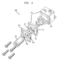
- FIGURE 3 illustrated is an exploded isometric view of an embodiment of the miniature liquid transfer pump 100 with a mounting plate 310.
- the mounting plate 310 is coupled to the housing 110 adjacent to the micro-motor 160 so that the drive shaft 165 on the micro-motor 160 passes through a mounting plate aperture 315 in the mounting plate 310, before passing through the drive shaft aperture 131 of the impeller chamber 130.
- the mounting plate 310 provides additional stiffness and rigidity to the micro-motor 160.
- a mounting plate o-ring seal 311 located between the second block 125 and the mounting plate 310 to aid in keeping the impeller chamber 130 leak-resistant.
- FIGURE 4A illustrated is an exploded isometric view of an embodiment of the miniature liquid transfer pump 100 where the first and second blocks 120, 125 are joined together and are fastened by clips 410.
- the first and second blocks 120, 125 each have a clip receptacle 415 to receive and secure the clips 410 when the housing 110 is assembled.
- an alignment feature 420 is located on a surface 425 of one of the first 120 and second blocks 125 (in this instance, the second block 125) that is joinable to a surface 426 (not visible) of the other of the first 120 or second 125 blocks (in this instance, the first block 120) which has a corresponding alignment feature receptacle 421 (not visible).
- the alignment feature 420 and alignment feature receptacle 420 assist in assembling the housing 110 by providing a positive indication that the first and second blocks 120, 125 are correctly aligned.
- the alignment feature 420 also provides additional support to the housing 110 by preventing rotation or separation when opposing torques are applied to the first and second blocks 120, 125, respectively.
- FIGURE 4A Also illustrated in FIGURE 4A is a feature that provides for the impeller 140 to have a vane 240 that is flat. This contrasts with prior art vanes used in larger pumps where the blades are typically curved.
- FIGURE 4B illustrated is the pump 100 of FIGURE 4A as assembled. As described above, the first and second blocks 120, 125 are secured to one another by clips 410.
- the assembled pump 100 in FIGURE 4B illustrates a housing 110 that has a block shape. In one embodiment of the invention the block-shaped housing 110 is constructed so that each side of the housing is less than about one inch long.
- FIGURE 5A illustrated is an exploded isometric view of an embodiment of a miniature liquid transfer pump 100 incorporating a fluid reservoir 510 in its construction.
- a fluid reservoir 510 is coupled to the impeller chamber 130 inlet 132.
- the reservoir 510 acts as a buffer to regulate the flow of fluid passing through the pump 100.
- the illustrated pump 100 is held together by clips 410.
- Illustrated in FIGURE 5B is an assembled view of the pump 100 and a fluid reservoir 510 as held together by clips 410.
- FIGURE 6 illustrated is an exploded isometric view of an embodiment of a miniature liquid transfer pump 100 incorporating an alternative fluid reservoir 510 configuration.
- the illustrated fluid reservoir 600 is cylindrical, rather than block-shaped, as FIGURES 5A and 5B illustrated.
- the liquid transfer device 700 for transporting liquid.
- the liquid transfer device 700 has a pipe 710 with a source end 720 and a destination end 730. Coupled to the pipe 710 is an embodiment of a miniature liquid transfer pump 100, as described herein.
- the illustrated liquid transfer device 700 is used in an active cooling mechanism for controlling heat generated by an electronic component 740, to which the device 700 is coupled.
- the pump 100 circulates liquid coolant through a heat sink 750, where heat emitted by the electronic device 740 is gathered, and then through a heat radiation section 740 where the heat is dissipated into the surrounding ambient air.
- the illustrated active cooling mechanism is described in detail in co-pending U.S. Patent Application Serial No. 09/482,839, entitled "Integrated Active Liquid Cooling Device For Board Mounted Electronic Components," filed on January 13, 2000, to Chen, et . al ., commonly assigned with the invention and incorporated herein by this reference.
Landscapes
- Engineering & Computer Science (AREA)
- Mechanical Engineering (AREA)
- General Engineering & Computer Science (AREA)
- Structures Of Non-Positive Displacement Pumps (AREA)
- Reciprocating Pumps (AREA)
Abstract
Description
the invention in its broadest form.
Claims (23)
- A miniature liquid transfer pump, comprising:a housing including first and second blocks joinable to form a leak-resistant impeller chamber having a drive shaft aperture, an inlet and an outlet;an impeller located in said impeller chamber; anda micro-motor having a drive shaft extending therefrom, that is mounted to said housing such that said drive shaft passes through said drive shaft aperture and engages said impeller to drive said impeller thereby to draw liquid through said inlet and eject said liquid through said outlet.
- The pump as recited in Claim 1 wherein said impeller has a vane with a notch thereon.
- The pump as recited in Claim 1 wherein said impeller has a flat vane.
- The pump as recited in Claim 1 further comprising a sealing plate on said impeller, said sealing plate transversely oriented to the rotational axis of said impeller.
- The pump as recited in Claim 1 further comprising a mounting plate having a mounting plate aperture therein, said mounting plate coupled to said housing adjacent said micro-motor such that said drive shaft passes through said mounting plate aperture before passing through said drive shaft aperture.
- The pump as recited in Claim 1 wherein an alignment feature is located on a surface of one of said first and second blocks joinable to a surface of the other of said first and second blocks with an alignment feature receptacle located thereon.
- The pump as recited in Claim 1 further comprising a clip securing said first and second blocks together.
- The pump as recited in Claim 1 further comprising a fluid reservoir coupled to said inlet.
- The pump as recited in Claim 8 further comprising a clip securing said reservoir to said housing.
- The pump as recited in Claim 1 wherein said housing has a block shape.
- The pump as recited in Claim 10 wherein each side of said block shape has a dimension of less than about one inch.
- A method of manufacturing a miniature liquid transfer pump, comprising:forming a housing that includes first and second blocks joinable to form a leak-resistant impeller chamber having a drive shaft aperture, an inlet and an outlet;forming an impeller to be located in said impeller chamber; andproviding a micro-motor having a drive shaft extending therefrom, that is mounted to said housing such that said drive shaft passes through said drive shaft aperture and engages said impeller to drive said impeller thereby to draw liquid through said inlet and eject said liquid through said outlet.
- The method as recited in Claim 12 wherein said impeller has a vane with a notch thereon.
- The method as recited in Claim 12 wherein said impeller has a flat vane.
- The method as recited in Claim 12 further comprising a forming a sealing plate on said impeller, said sealing plate transversely oriented to the rotational axis of said impeller.
- The method as recited in Claim 12 further comprising a forming a mounting plate having a mounting plate aperture therein, and coupling said mounting plate to said housing adjacent said micro-motor such that said drive shaft passes through said mounting plate aperture before passing through said drive shaft aperture.
- The method as recited in Claim 12 wherein an alignment feature is formed on a surface of one of said first and second blocks joinable to a surface of the other of said first and second blocks with an alignment feature receptacle located thereon.
- The method as recited in Claim 12 further comprising providing a clip securing said first and second blocks together.
- The method as recited in Claim 12 further comprising coupling a fluid reservoir to said inlet.
- The method as recited in Claim 19 further comprising securing said reservoir to said housing with a clip.
- The method as recited in Claim 12 wherein said housing has a block shape.
- The method as recited in Claim 21 wherein each side of said block shape has a dimension of less than about one inch.
- For transporting liquid, a liquid transfer device, comprising;a pipe having a source end and a destination end; anda miniature liquid transfer pump as claimed in any of claims 1 to 11 coupled to said pipe.
Applications Claiming Priority (2)
| Application Number | Priority Date | Filing Date | Title |
|---|---|---|---|
| US09/505,086 US6386844B1 (en) | 2000-02-16 | 2000-02-16 | Miniature liquid transfer pump and method of manufacturing same |
| US505086 | 2000-02-16 |
Publications (2)
| Publication Number | Publication Date |
|---|---|
| EP1126181A2 true EP1126181A2 (en) | 2001-08-22 |
| EP1126181A3 EP1126181A3 (en) | 2002-01-16 |
Family
ID=24008941
Family Applications (1)
| Application Number | Title | Priority Date | Filing Date |
|---|---|---|---|
| EP01301027A Withdrawn EP1126181A3 (en) | 2000-02-16 | 2001-02-06 | Miniature pump |
Country Status (3)
| Country | Link |
|---|---|
| US (1) | US6386844B1 (en) |
| EP (1) | EP1126181A3 (en) |
| JP (1) | JP2001248585A (en) |
Cited By (2)
| Publication number | Priority date | Publication date | Assignee | Title |
|---|---|---|---|---|
| CN101737339B (en) * | 2002-09-13 | 2012-07-18 | 日立空调·家用电器株式会社 | Air conditioner |
| CN110863994A (en) * | 2019-12-26 | 2020-03-06 | 江苏盐邦泵业制造有限公司 | Novel take mixed flow pump of water conservancy diversion device |
Families Citing this family (15)
| Publication number | Priority date | Publication date | Assignee | Title |
|---|---|---|---|---|
| US7500543B2 (en) * | 2000-01-24 | 2009-03-10 | Doran Paul J | Sheave with taper lock coupler |
| US6681898B1 (en) * | 2000-01-24 | 2004-01-27 | Paul J. Doran | Coupling arrangement for coupling a motor to a hoist machine |
| US7407040B2 (en) * | 2000-01-24 | 2008-08-05 | Doran Paul J | Tapered coupler for coupling a motor to a hoist machine |
| US6315080B1 (en) * | 2000-01-24 | 2001-11-13 | Paul J. Doran | Converter arrangement for modular motor |
| US6926207B2 (en) * | 2003-07-24 | 2005-08-09 | Frank J. Perhats, Sr. | Divided or interconnected after-run vehicle interior heating system |
| US8585379B2 (en) | 2005-08-05 | 2013-11-19 | Molon Motor And Coil Corporation | Peristaltic pump that is resistant to torques and vibrations |
| US8469682B2 (en) * | 2005-08-05 | 2013-06-25 | Molon Motor And Coil Corporation | Peristaltic pump with torque relief |
| US20090092507A1 (en) * | 2005-08-05 | 2009-04-09 | Ramirez Jr Emilio A | Fluid pump systems |
| US20070031272A1 (en) * | 2005-08-05 | 2007-02-08 | Molon Motor And Coil Corporation | Peristaltic pump |
| TWI259247B (en) * | 2005-11-01 | 2006-08-01 | Sunonwealth Electr Mach Ind Co | Fluid pump |
| US20070109746A1 (en) * | 2005-11-15 | 2007-05-17 | Klein David A | Liquid cooling of electronic system and method |
| WO2009089466A2 (en) * | 2008-01-09 | 2009-07-16 | Keck Graduate Institute | System, apparatus and method for material preparation and/or handling |
| US7958796B2 (en) * | 2008-11-12 | 2011-06-14 | Hiwin Technologies Corp. | Screw-driven fan device |
| PL3379084T3 (en) * | 2017-03-23 | 2020-05-18 | Xylem Europe Gmbh | De-blocking device for a hydraulic pump |
| RU2688872C1 (en) * | 2017-11-29 | 2019-05-22 | Акционерное общество "Информационные спутниковые системы" имени академика М.Ф. Решетнёва" | Production method of electric pump unit |
Family Cites Families (19)
| Publication number | Priority date | Publication date | Assignee | Title |
|---|---|---|---|---|
| GB311172A (en) * | 1928-10-01 | 1929-05-09 | Albert Saunders | Improvements in and relating to centrifugal pumps |
| US2622537A (en) * | 1950-11-02 | 1952-12-23 | Cincinnati Milling Machine Co | Pumping mechanism |
| US2969908A (en) * | 1953-04-27 | 1961-01-31 | Garrett Corp | Impulse axial-flow compressor |
| US2931307A (en) * | 1957-12-04 | 1960-04-05 | Gorman Rupp Ind Inc | Enclosed rotor construction for motor pump unit |
| GB1043468A (en) * | 1964-06-25 | 1966-09-21 | Beresford James & Son Ltd | Electrically driven circulating pump |
| US3847505A (en) * | 1973-02-20 | 1974-11-12 | D Treese | Flow through impellers and fluid machines employing same |
| US4076179A (en) * | 1976-04-22 | 1978-02-28 | Kabushiki Kaisha Sogo Pump Seisakusho | Centrifugal sewage pump |
| US4308994A (en) * | 1978-06-01 | 1982-01-05 | Autotherm, Inc. | Energy saving circulating system for vehicle heaters |
| US5100288A (en) * | 1990-06-15 | 1992-03-31 | Atsco, Inc. | Slurry pump apparatus |
| US5316077A (en) * | 1992-12-09 | 1994-05-31 | Eaton Corporation | Heat sink for electrical circuit components |
| JP3315224B2 (en) * | 1993-12-09 | 2002-08-19 | 千寿製薬株式会社 | Micro flow pump |
| US5788468A (en) * | 1994-11-03 | 1998-08-04 | Memstek Products, Llc | Microfabricated fluidic devices |
| GB2307947B (en) * | 1995-12-08 | 1999-08-18 | Aisan Ind | Magnetically coupled pump |
| US5731954A (en) * | 1996-08-22 | 1998-03-24 | Cheon; Kioan | Cooling system for computer |
| US5835350A (en) | 1996-12-23 | 1998-11-10 | Lucent Technologies Inc. | Encapsulated, board-mountable power supply and method of manufacture therefor |
| JP3869090B2 (en) * | 1997-10-16 | 2007-01-17 | アスモ株式会社 | Washer pump device |
| TW477492U (en) * | 1998-07-27 | 2002-02-21 | Sunonwealth Electr Mach Ind Co | Associating structure of air pumping fan |
| US6000919A (en) * | 1999-02-17 | 1999-12-14 | Hsieh; Hsin-Mao | Fan with reduced thickness |
| US6077037A (en) * | 1999-03-12 | 2000-06-20 | Lockheed Martin Corporation | Quick-change fan mechanism |
-
2000
- 2000-02-16 US US09/505,086 patent/US6386844B1/en not_active Expired - Lifetime
-
2001
- 2001-02-06 EP EP01301027A patent/EP1126181A3/en not_active Withdrawn
- 2001-02-06 JP JP2001029558A patent/JP2001248585A/en not_active Abandoned
Cited By (2)
| Publication number | Priority date | Publication date | Assignee | Title |
|---|---|---|---|---|
| CN101737339B (en) * | 2002-09-13 | 2012-07-18 | 日立空调·家用电器株式会社 | Air conditioner |
| CN110863994A (en) * | 2019-12-26 | 2020-03-06 | 江苏盐邦泵业制造有限公司 | Novel take mixed flow pump of water conservancy diversion device |
Also Published As
| Publication number | Publication date |
|---|---|
| US6386844B1 (en) | 2002-05-14 |
| EP1126181A3 (en) | 2002-01-16 |
| JP2001248585A (en) | 2001-09-14 |
Similar Documents
| Publication | Publication Date | Title |
|---|---|---|
| US6386844B1 (en) | Miniature liquid transfer pump and method of manufacturing same | |
| US5966286A (en) | Cooling system for thin profile electronic and computer devices | |
| US6981543B2 (en) | Modular capillary pumped loop cooling system | |
| US7319587B2 (en) | Electronic apparatus having pump unit | |
| KR100310099B1 (en) | Radiating device for semiconductor integrated circuit device and portable computer having same | |
| CN101802748B (en) | Liquid cooling unit and electronic device | |
| US7554805B2 (en) | Heat dissipation structure for electronic devices | |
| US7626815B2 (en) | Drive bay heat exchanger | |
| US20080173427A1 (en) | Electronic component cooling | |
| US20070029069A1 (en) | Water-cooling heat dissipation device | |
| CN1293774A (en) | System for cooling devices inside a computer | |
| JP2011233849A (en) | Cooling device, electronics and heat sink | |
| JP5148079B2 (en) | Heat exchanger for liquid cooling unit, liquid cooling unit and electronic equipment | |
| US20060249278A1 (en) | Liquid cooling system suitable for removing heat from electronic components | |
| US20060018775A1 (en) | Liquid circulation system and liquid cooling system therewith | |
| US20120057301A1 (en) | Heat dissipation apparatus and electronic device incorporating same | |
| KR20050081815A (en) | Electronic device equipped with liquid cooling system, and radiator and manufacturing method thereof | |
| JP4842040B2 (en) | Electronics | |
| US20050183848A1 (en) | Coolant tray of liquid based cooling device | |
| US20070110592A1 (en) | Integrated liquid cooling system | |
| JP4781929B2 (en) | Electronics | |
| JP2006234255A (en) | RADIATOR AND LIQUID COOLING SYSTEM HAVING THE RADIATOR | |
| US11943895B2 (en) | Liquid cooling device and electronic device | |
| US6529376B2 (en) | System processor heat dissipation | |
| US20050217828A1 (en) | Pump, cooler, and electronic device |
Legal Events
| Date | Code | Title | Description |
|---|---|---|---|
| PUAI | Public reference made under article 153(3) epc to a published international application that has entered the european phase |
Free format text: ORIGINAL CODE: 0009012 |
|
| AK | Designated contracting states |
Kind code of ref document: A2 Designated state(s): DE FR GB Kind code of ref document: A2 Designated state(s): AT BE CH CY DE DK ES FI FR GB GR IE IT LI LU MC NL PT SE TR |
|
| AX | Request for extension of the european patent |
Free format text: AL;LT;LV;MK;RO;SI |
|
| PUAL | Search report despatched |
Free format text: ORIGINAL CODE: 0009013 |
|
| AK | Designated contracting states |
Kind code of ref document: A3 Designated state(s): AT BE CH CY DE DK ES FI FR GB GR IE IT LI LU MC NL PT SE TR |
|
| AX | Request for extension of the european patent |
Free format text: AL;LT;LV;MK;RO;SI |
|
| RIC1 | Information provided on ipc code assigned before grant |
Free format text: 7F 04D 29/62 A, 7F 04D 13/06 B |
|
| 17P | Request for examination filed |
Effective date: 20020708 |
|
| AKX | Designation fees paid |
Free format text: DE FR GB |
|
| STAA | Information on the status of an ep patent application or granted ep patent |
Free format text: STATUS: THE APPLICATION HAS BEEN WITHDRAWN |
|
| 18W | Application withdrawn |
Effective date: 20031114 |