EP1126159A2 - Key system for ecological filter cartridge and element - Google Patents
Key system for ecological filter cartridge and element Download PDFInfo
- Publication number
- EP1126159A2 EP1126159A2 EP01301343A EP01301343A EP1126159A2 EP 1126159 A2 EP1126159 A2 EP 1126159A2 EP 01301343 A EP01301343 A EP 01301343A EP 01301343 A EP01301343 A EP 01301343A EP 1126159 A2 EP1126159 A2 EP 1126159A2
- Authority
- EP
- European Patent Office
- Prior art keywords
- filter
- key
- housing
- filter cartridge
- filter unit
- Prior art date
- Legal status (The legal status is an assumption and is not a legal conclusion. Google has not performed a legal analysis and makes no representation as to the accuracy of the status listed.)
- Granted
Links
- 230000002093 peripheral effect Effects 0.000 claims description 9
- 230000000295 complement effect Effects 0.000 claims description 8
- 239000012530 fluid Substances 0.000 claims description 4
- 239000000446 fuel Substances 0.000 abstract description 35
- 239000011159 matrix material Substances 0.000 abstract description 5
- 239000002131 composite material Substances 0.000 abstract description 3
- 238000002485 combustion reaction Methods 0.000 description 8
- 230000000717 retained effect Effects 0.000 description 8
- 238000001914 filtration Methods 0.000 description 7
- 239000002283 diesel fuel Substances 0.000 description 4
- 239000002245 particle Substances 0.000 description 4
- 239000002699 waste material Substances 0.000 description 4
- XLYOFNOQVPJJNP-UHFFFAOYSA-N water Substances O XLYOFNOQVPJJNP-UHFFFAOYSA-N 0.000 description 4
- 238000002347 injection Methods 0.000 description 3
- 239000007924 injection Substances 0.000 description 3
- 239000000463 material Substances 0.000 description 3
- 230000000694 effects Effects 0.000 description 2
- 230000007613 environmental effect Effects 0.000 description 2
- 238000007789 sealing Methods 0.000 description 2
- 230000006978 adaptation Effects 0.000 description 1
- 230000002411 adverse Effects 0.000 description 1
- 230000000712 assembly Effects 0.000 description 1
- 238000000429 assembly Methods 0.000 description 1
- 230000004323 axial length Effects 0.000 description 1
- 230000009977 dual effect Effects 0.000 description 1
- 230000008014 freezing Effects 0.000 description 1
- 238000007710 freezing Methods 0.000 description 1
- 238000010348 incorporation Methods 0.000 description 1
- 238000003780 insertion Methods 0.000 description 1
- 230000037431 insertion Effects 0.000 description 1
- 238000009434 installation Methods 0.000 description 1
- 230000002452 interceptive effect Effects 0.000 description 1
- 238000012423 maintenance Methods 0.000 description 1
- 230000013011 mating Effects 0.000 description 1
- 239000002184 metal Substances 0.000 description 1
- 238000012986 modification Methods 0.000 description 1
- 230000004048 modification Effects 0.000 description 1
- 239000013618 particulate matter Substances 0.000 description 1
- 238000003908 quality control method Methods 0.000 description 1
- 238000004064 recycling Methods 0.000 description 1
Images





Classifications
-
- B—PERFORMING OPERATIONS; TRANSPORTING
- B01—PHYSICAL OR CHEMICAL PROCESSES OR APPARATUS IN GENERAL
- B01D—SEPARATION
- B01D29/00—Filters with filtering elements stationary during filtration, e.g. pressure or suction filters, not covered by groups B01D24/00 - B01D27/00; Filtering elements therefor
- B01D29/11—Filters with filtering elements stationary during filtration, e.g. pressure or suction filters, not covered by groups B01D24/00 - B01D27/00; Filtering elements therefor with bag, cage, hose, tube, sleeve or like filtering elements
- B01D29/13—Supported filter elements
- B01D29/15—Supported filter elements arranged for inward flow filtration
-
- B—PERFORMING OPERATIONS; TRANSPORTING
- B01—PHYSICAL OR CHEMICAL PROCESSES OR APPARATUS IN GENERAL
- B01D—SEPARATION
- B01D35/00—Filtering devices having features not specifically covered by groups B01D24/00 - B01D33/00, or for applications not specifically covered by groups B01D24/00 - B01D33/00; Auxiliary devices for filtration; Filter housing constructions
- B01D35/30—Filter housing constructions
-
- F—MECHANICAL ENGINEERING; LIGHTING; HEATING; WEAPONS; BLASTING
- F02—COMBUSTION ENGINES; HOT-GAS OR COMBUSTION-PRODUCT ENGINE PLANTS
- F02M—SUPPLYING COMBUSTION ENGINES IN GENERAL WITH COMBUSTIBLE MIXTURES OR CONSTITUENTS THEREOF
- F02M37/00—Apparatus or systems for feeding liquid fuel from storage containers to carburettors or fuel-injection apparatus; Arrangements for purifying liquid fuel specially adapted for, or arranged on, internal-combustion engines
- F02M37/22—Arrangements for purifying liquid fuel specially adapted for, or arranged on, internal-combustion engines, e.g. arrangements in the feeding system
- F02M37/32—Arrangements for purifying liquid fuel specially adapted for, or arranged on, internal-combustion engines, e.g. arrangements in the feeding system characterised by filters or filter arrangements
- F02M37/34—Arrangements for purifying liquid fuel specially adapted for, or arranged on, internal-combustion engines, e.g. arrangements in the feeding system characterised by filters or filter arrangements by the filter structure, e.g. honeycomb, mesh or fibrous
-
- F—MECHANICAL ENGINEERING; LIGHTING; HEATING; WEAPONS; BLASTING
- F02—COMBUSTION ENGINES; HOT-GAS OR COMBUSTION-PRODUCT ENGINE PLANTS
- F02M—SUPPLYING COMBUSTION ENGINES IN GENERAL WITH COMBUSTIBLE MIXTURES OR CONSTITUENTS THEREOF
- F02M37/00—Apparatus or systems for feeding liquid fuel from storage containers to carburettors or fuel-injection apparatus; Arrangements for purifying liquid fuel specially adapted for, or arranged on, internal-combustion engines
- F02M37/22—Arrangements for purifying liquid fuel specially adapted for, or arranged on, internal-combustion engines, e.g. arrangements in the feeding system
- F02M37/32—Arrangements for purifying liquid fuel specially adapted for, or arranged on, internal-combustion engines, e.g. arrangements in the feeding system characterised by filters or filter arrangements
- F02M37/42—Installation or removal of filters
-
- B—PERFORMING OPERATIONS; TRANSPORTING
- B01—PHYSICAL OR CHEMICAL PROCESSES OR APPARATUS IN GENERAL
- B01D—SEPARATION
- B01D2201/00—Details relating to filtering apparatus
- B01D2201/30—Filter housing constructions
- B01D2201/301—Details of removable closures, lids, caps, filter heads
-
- B—PERFORMING OPERATIONS; TRANSPORTING
- B01—PHYSICAL OR CHEMICAL PROCESSES OR APPARATUS IN GENERAL
- B01D—SEPARATION
- B01D2201/00—Details relating to filtering apparatus
- B01D2201/34—Seals or gaskets for filtering elements
-
- B—PERFORMING OPERATIONS; TRANSPORTING
- B01—PHYSICAL OR CHEMICAL PROCESSES OR APPARATUS IN GENERAL
- B01D—SEPARATION
- B01D2201/00—Details relating to filtering apparatus
- B01D2201/40—Special measures for connecting different parts of the filter
- B01D2201/4046—Means for avoiding false mounting of different parts
-
- B—PERFORMING OPERATIONS; TRANSPORTING
- B01—PHYSICAL OR CHEMICAL PROCESSES OR APPARATUS IN GENERAL
- B01D—SEPARATION
- B01D2201/00—Details relating to filtering apparatus
- B01D2201/40—Special measures for connecting different parts of the filter
- B01D2201/4076—Anti-rotational means
-
- B—PERFORMING OPERATIONS; TRANSPORTING
- B01—PHYSICAL OR CHEMICAL PROCESSES OR APPARATUS IN GENERAL
- B01D—SEPARATION
- B01D2201/00—Details relating to filtering apparatus
- B01D2201/40—Special measures for connecting different parts of the filter
- B01D2201/4092—Threaded sections, e.g. screw
-
- F—MECHANICAL ENGINEERING; LIGHTING; HEATING; WEAPONS; BLASTING
- F02—COMBUSTION ENGINES; HOT-GAS OR COMBUSTION-PRODUCT ENGINE PLANTS
- F02M—SUPPLYING COMBUSTION ENGINES IN GENERAL WITH COMBUSTIBLE MIXTURES OR CONSTITUENTS THEREOF
- F02M37/00—Apparatus or systems for feeding liquid fuel from storage containers to carburettors or fuel-injection apparatus; Arrangements for purifying liquid fuel specially adapted for, or arranged on, internal-combustion engines
- F02M37/22—Arrangements for purifying liquid fuel specially adapted for, or arranged on, internal-combustion engines, e.g. arrangements in the feeding system
- F02M37/24—Arrangements for purifying liquid fuel specially adapted for, or arranged on, internal-combustion engines, e.g. arrangements in the feeding system characterised by water separating means
Definitions
- This invention relates generally to fuel filters employed in connection with internal combustion engines. More particularly, the present invention relates to fuel filter systems having a replaceable cartridge for removing foreign particles and/or separating water from fuel of the fuel supply system of an internal combustion engine.
- a number of conventional fuel filter systems perform the dual functions of removing particulate matter from the diesel fuel and separating water from the fuel.
- the fuel filter systems employ a disposable filter cartridge which is replaced at pre-established intervals of filter usage.
- the filter cartridge requirements may vary depending upon such characteristics as the type and make of the internal combustion engine, the specific applications for which the engine is employed, the climate in which the combustion engine is operated and/or regional characteristics as to the quality of the fuel supply.
- the filter cartridges thus commonly vary as to their dimensions, their capacity, and the qualities of their filter media.
- Fuel filter systems commonly comprise fuel inlet and outlets disposed in a base and a disposable filter cartridge which mounts to the base.
- Disposable filter cartridges constructed according to this invention have slots which are designed to mate with axial projections of the base. The projections interfere with the use of an incompatible cartridge by interfering with the mounting and sealing of the cartridge to the base.
- Fuel filters have typically been constructed in the form of a metal can, permanently enclosing the filter element in a single use assembly. While these assemblies have proved to be effective and reliable, they are less than ideal in terms of waste of materials and disposal cost. Increased awareness of environmental protection and recycling of materials have led to a need for more efficient filtration systems having a minimum disposable component. In addition, environmental protection agencies seeking to reduce the volume of waste items associated with the automotive and trucking industries may no longer permit unrestricted disposal of used fuel filters into the normal waste stream, thereby necessitating specialized and consequently more expensive disposal.
- the present invention provides a filter cartridge assembly comprising:
- the invention in a preferred form provides a filter cartridge assembly including a two-part housing and replaceable filter unit wherein the assembly incorporates a key system for keying the replaceable filter unit to the cartridge.
- the housing is constructed of first and second cooperative sections, detachably connected to allow replacement of the used filter unit.
- each housing section is can-shaped, having a closed first end and an open second end.
- the filter unit comprises a continuous, fan shaped, pleated filter element, typically composed of a form of paper.
- Axially spaced'first and second end caps provide support structure for the filter element and also provide a platform for the attachment of grommets which seal the unit to the fuel inlet/outlet conduit.
- At least one tab or key radially projects from either the housing first section or the filter unit first end cap.
- a corresponding keyway in either the other housing first section or the filter unit first end cap is dimensioned and located for receiving the corresponding key.
- the keyway in the housing first section takes the form of a slot having an axial portion and an offset portion generally perpendicular to the axial portion.
- the filter unit is guided into the housing first section axially along the cooperative keyway and key structure.
- the first end cap preferably includes a radially inward projecting shoulder which, during insertion, rides over radially outward projecting ribs on the housing grommet. The ribs engage the shoulder so that the filter unit is held axially within the housing first section. In this manner the filter unit is captured and retained by the housing first section.
- the cooperative keyway and key structures function as a key system to prevent the use of incompatible filter units in a particular housing.
- the angular dimension of the key will be matched by the arcuate extent of the axial portion of the keyway, and the axial dimension of the offset portion of the keyway will match the axial dimension of the key.
- a filter unit having a key with an incorrect angular dimension will not be accepted in the axial portion of the keyway defined by the housing first section.
- a filter unit having a key with an incorrect axial dimension will not properly engage the offset portion of the keyway.
- the keys project radially from the filter unit first end cap and have radial and angular dimensions complementary with the corresponding radial depth and arcuate extent of the keyway defined by the housing first section.
- the filter unit key is accepted in the axial portion of the keyway, the filter unit is guided into mating position within the housing first section.
- the housing second section is then connected to the housing first section to form a sealed enclosure surrounding the filter unit.
- the assembled housing and filter unit form a filter cartridge assembly which can be used to replace conventional, sealed filter cartridges in fuel filter systems and other applications.
- the key system ensures replacement filter unit compatibility for various filter cartridges having common dimensions.
- Unique sets of keys and keyways may be selected to form a composite compatibility matrix for each desired filter unit capacity, filter media or other characteristic, including compliance with ecological regulations or manufacturer specifications.
- the present invention provides a filter cartridge housing comprising:
- the present invention provides a filter unit comprising:
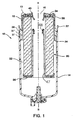
- Filter cartridge assembly 10 includes first and second detachably connectable sections which retain and surround a filter unit 30.
- the filter unit 30 has a defined useful life and is periodically replaced with a compatible filter unit.
- the filter cartridge assembly 10 is especially adapted for incorporation into the fuel filter system of an internal combustion engine (not illustrated) such as a diesel engine.
- the filter cartridge assembly is intended to reduce waste by allowing replacement of only the spent filter unit, rather than the entire cartridge.
- the filter unit is constructed of materials which allow disposal by incineration.
- the present invention is not limited to any specific filter cartridge assembly, but is generally applicable to any filter cartridge assembly employing a housing which may be disassembled to allow replacement of a spent filter unit retained therein.
- a filter cartridge assembly 10 in accordance with the present invention includes a housing first section 12 and a cooperative second section 14 which are detachably connectable to form a fluid tight enclosure.
- a threaded connection between the housing sections is illustrated.
- Complementary threads 37, 37' project from the housing first and second sections, respectively.
- each housing section 12, 14 includes a retainer bump 43, 43' located so that the housing sections must deform to permit one bump to ride over the other as the housing sections rotate relative to each other.
- the housing first section 12 includes a stop 21 arranged to define the fully engaged position of the threaded connection. Retaining bump 43' rides over retaining bump 43 and then encounters the stop 21.
- a filter unit 30 is captured and retained within the enclosure by the housing first section 12.
- the filter unit 30 includes a generally continuous filter element 32, a first end cap 34 and a second end cap 36.
- the end caps 34, 36 enclose the axially spaced ends of the filter element 32 and provide structure to the paper element.
- the peripheral portion 35 of the first end cap 34 includes radially extending keys 38 configured to engage axial portions 24 of the keyway defined by the interior structure 26 of the housing first section 12.
- the second end cap 36 includes a tubular axial projection 47 extending toward the first end cap 34.
- the tubular projection 47 terminates in a structure configured to engage and retain a sealing grommet 48.
- the first end cap 34 includes a radially inward extending shoulder 42 defining a central opening 46 configured for receiving an axially extending tubular portion 44 of the housing grommet 40.
- the radially inwardly projecting shoulder 42 of the first end cap 34 engages the axially extending tubular portion 44 of the housing grommet 40.
- the radially extending shoulder 42 is axially positioned to engage an intermediate portion of the housing grommet 40, exerting a radially inward force on that intermediate portion.
- the tubular grommet 40 includes at least one radially protruding rib 45.
- the inward projecting shoulder 42 rides over the ribs 45 during installation.
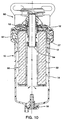
- a fuel filter system for which the filter cartridge assembly 10 of the present invention is particularly suited is illustrated in Figure 10.
- a filter base module 60 forms a receptacle for receiving the filter cartridge assembly 10.
- a coaxial fuel inlet/outlet conduit projects from the filter base module 60 into the filter cartridge assembly 10 through a central opening 16 in the housing first section 12.
- the fuel inlet/outlet conduit includes an inlet conduit 54 surrounded by a coaxial outlet conduit 52.
- the housing grommet 40 surrounds and seals the housing first end 12 to the outlet conduit 52.
- FIG 10 illustrates a base module 60 and associated filter cartridge assembly 10 adapted for a standard flow path of fuel through the filter element 32.
- the greater axial length of the fuel inlet conduit 54 provides an end location which is engaged by a grommet 48 retained on the tubular axial projection 47 of the filter unit second end cap 36.
- the sealed engagement between the fuel inlet conduit 54 and the tubular axial projection 47 forms a fuel inlet path directing fuel axially into the housing second section 14 where it flows radially and axially to the filter element 32 in the general direction of the Figure 10 arrows. Passing radially through the filter element 32, the filtered fuel then flows generally axially into the fuel outlet conduit 52.
- a threaded collar 62 passes over the filter cartridge assembly 10 and engages a molded lip structure 27 extending from the housing second section 14.
- the collar 62 threadably engages complementary threads on the filter base module 60, retaining the filter cartridge assembly 10 in a stable mated position with the filter base module 60.
- the base module 60 and collar 62 prevent the housing sections 12, 14 from deforming and make it impossible for the two housing sections 12, 14 to disengage from each other.
- the portion of a base module 60 which receives and mates with the filter cartridge assembly 10 will typically have a standard configuration.
- the external configuration of the first end 13 of a filter cartridge assembly adapted to mate with the filter base module 60 will be generally similar. While the size and configuration of the filter base module may be standardized, such base modules are compatible with applications requiring different filtering and flow capabilities.
- the internal configuration of the filter cartridge assembly, i.e., the filter unit 30, may differ significantly.
- the present invention ensures that only compatible filter units 30 may be installed by providing cooperative keyway and key structures on the housing first section 12 and the filter unit 30 to thereby key the filter unit to the housing.
- FIGS 3 and 4 illustrate the configuration of the housing first section 12.
- the interior structure 26 of the housing first section 12 defines keyways, the axial portions 24 of which extend from the housing first section 12 second end 15 toward the first end 13.
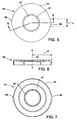
- FIGS 5 - 7 illustrate the complementary structure of the filter unit first end cap 34.
- the filter unit first end cap 34 has a generally circular peripheral portion 35 which includes radially extending keys 38.
- the keys 38 extend from the first end cap 34 in at least two dimensions to define a compatibility matrix for the filter unit.
- the compatibility matrix may be further described by the key geometry as follows:
- the embodiment illustrated in Figures 3 - 7 illustrates a housing first section 12 interior structure 26 which defines two equal size, equal depth, keyway axial portions 24.
- the illustrated first end cap 34 includes two keys having equal angular dimensions L, projecting equal radial distances R.
- the structure of the keys 38 illustrated in Figures 5 - 7 is complementary to and cooperative with the structure of the keyway axial portions 24, illustrated in Figures 3 and 4.
- the keys 38 are aligned with and received in the keyway axial portions 24 allowing the filter unit 30 to be inserted into the housing first section 12.
- the radially inward projecting shoulder 42 is engaged with the tubular portion of the housing grommet 40.
- the filter unit 30 is captured and retained in a particular axial position within the housing first section 12.
- the key structure of a filter unit must have the correct number of keys in the correct angular positions, each key having the correct geometry, e.g., the correct radial and angular dimensions. Only when a correctly configured filter unit has been fully received and retained may the housing second section 14 be threadably engaged with the housing first section to form a sealed filter cartridge assembly for use in conjunction with a base module 60.
- Figures 8 and 9 illustrate a configuration which varies the angular dimension L of the keys 38.
- Figure 8 illustrates a first end cap 34 where each key 38 subtends an obtuse angle of approximately 140°.
- Each key 38 has an equivalent radial projection R.
- Figure 9 illustrates a bottom view of a housing first section 12 configured to receive the first end cap 34 illustrated in Figure 8.
- the interior structure 26 defines keyway axial portions 24 which extend most of the way around one-half of the interior structure 26.
- Figures 11 and 12 illustrate a further alternative configuration of keys and keyways in accordance with the present invention.
- Figure 11 is a top plan view of a filter unit first end cap 34 having three radially projecting keys 38, 38'. Two of the three keys 38 have equal angular dimensions L and project equivalent radial distances R, while one key 38' projects a greater radial distance R 1 and has a smaller angular dimension L 1 .
- Figure 12 illustrates a housing first section 12 with compatibly configured keyway axial portions 24, 24'.
- a composite compatibility matrix comprising an infinite number of configuration sets are available to differentiate between filter units 30 having differing flow capacities, filter media, disposal options, ecological qualities or other characteristics.
- the matching key and keyway structures define compatible housings and filter units.
- the key and keyway structures are positioned and configured so that incompatible housings and filter units cannot be readily assembled. For example, an incorrectly keyed filter unit will not be properly received in the housing first section, thus obstructing connection of the first and second housing sections. Requiring compatibility of the keys and keyways renders any attempt to defeat the key system highly problematical.
- the present invention at least in its preferred form, provides a new and improved filter cartridge assembly incorporating a system to key the replaceable filter unit to the housing; and furthermore provides a new and improved filter cartridge assembly which allows replacement of the filter unit and provides a key system which ensures only compatible units will be used; and furthermore provides a new and improved filter cartridge assembly key system wherein the filter unit is captured within the housing in particular axial position.
Landscapes
- Engineering & Computer Science (AREA)
- Chemical & Material Sciences (AREA)
- Chemical Kinetics & Catalysis (AREA)
- Combustion & Propulsion (AREA)
- Mechanical Engineering (AREA)
- General Engineering & Computer Science (AREA)
- Filtration Of Liquid (AREA)
- Lubrication Details And Ventilation Of Internal Combustion Engines (AREA)
- Liquid Carbonaceous Fuels (AREA)
Abstract
Description
- Each key 38 subtends an angle, producing an angular
dimension L which is measured along the
peripheral portion 35; and - Each key projects a radial distance R from a central axis B.
Claims (16)
- A filter cartridge assembly (10) comprising:a housing including a first section (12) having a first end (13) and a second section (14), said sections removably connectable to form a fluid-tight enclosure, said first section comprising an interior structure (26) defining at least one keyway including an axial portion (24) and an offset portion generally orthogonal thereto, anda filter unit (30) replaceably receivable in said enclosure, said filter unit including a filter element (32) and at least one end cap (34,36) enclosing an axial end of said filter element, said end cap including a peripheral portion (35) having at least one key (38) extending radially from said peripheral portion,wherein said key is receivable in said keyway and axially movable toward said first section first end.
- A filter cartridge assembly (10) as claimed in claim 1, wherein said axial portion (24) comprises an axially extending slot having a radial depth and an arcuate extent and said key (38) subtends an angle complementary to the arcuate extent of said axial portion.
- A filter cartridge assembly (10) as claimed in claim 1 or 2, wherein said interior structure (26) comprises a plurality of keyways and said end cap (34, 36) includes an equal plurality of radially extending keys receivable in said keyways.
- A filter cartridge assembly (10) as claimed in claim 3, wherein at least one axial portion (24) has an arcuate extent which differs from the corresponding arcuate extent of another axial portion and at least one key subtends an angle which is complementary with the arcuate extent of said at least one axial portion.
- A filter cartridge assembly (10) as claimed in any preceding claim, wherein at least one key (38) extends a radial distance (R) which differs from the corresponding radial extent (R') of another key (38') and at least one axial portion has a radial depth which is complementary with the radial extent of said at least one key.
- A filter cartridge housing (10) comprising:a can-shaped first section (12) including a central axis and first (13) and second (15) ends and an interior structure (26) defining at least one keyway including an axial portion (24), anda second section (14) including first and second ends,wherein said second ends are detachably connectable to form a fluid tight enclosure.
- A filter cartridge housing (10) as claimed in claim 6, wherein said axial portion (24) comprises an axially extending slot having a radial depth and an arcuate extent.
- A filter cartridge housing (10) as claimed in claim 6 or 7, wherein said interior structure (26) defines a plurality of keyways.
- A filter cartridge housing (10) as claimed in claim 8, wherein at least one keyway has a radial depth which differs from the corresponding radial depth of another keyway.
- A filter cartridge housing (10) as claimed in claim 8 or 9, wherein at least one axial portion (24) has an arcuate extent which differs from the corresponding arcuate extent of another axial portion (24').
- A filter cartridge housing (10) as claimed in any of claims 6 to 10, wherein said housing sections (12, 14) are threadably connectable and each of said first and second housing sections includes a retainer bump (43, 43') positioned so that said bumps must ride over each other to complete the threaded connection between said first and second housing sections.
- A filter unit (30) comprising:a filter element (32) having axially spaced ends and surrounding a central axis (B), andan end cap (34) enclosing an axial end of said element, said end cap including a generally arcuate peripheral portion having a center of curvature on said central axis and having at least one integral radially extending key (38) having an arcuate outer periphery with a center of curvature on said central axis.
- A filter unit (30) as claimed in claim 12, wherein said key (38) subtends an angle and has a radial extent relative to said axis.
- A filter unit (30) as claimed in claim 12 or 13, wherein said end cap (34,36) comprises a plurality of angularly spaced keys.
- A filter unit (30) as claimed in claim 14, wherein at least one key (38') extends a radial distance (R') which differs from the corresponding radial extent (R) of another key (38).
- A filter unit (30) as claimed in claim 14 or 15, wherein at least one key (38') subtends an angle which differs from the corresponding angular extent of another key (38).
Applications Claiming Priority (2)
| Application Number | Priority Date | Filing Date | Title |
|---|---|---|---|
| US18299300P | 2000-02-16 | 2000-02-16 | |
| US182993P | 2000-02-16 |
Publications (3)
| Publication Number | Publication Date |
|---|---|
| EP1126159A2 true EP1126159A2 (en) | 2001-08-22 |
| EP1126159A3 EP1126159A3 (en) | 2002-10-30 |
| EP1126159B1 EP1126159B1 (en) | 2006-11-08 |
Family
ID=22670951
Family Applications (1)
| Application Number | Title | Priority Date | Filing Date |
|---|---|---|---|
| EP01301343A Expired - Lifetime EP1126159B1 (en) | 2000-02-16 | 2001-02-16 | Key system for ecological filter cartridge and element |
Country Status (4)
| Country | Link |
|---|---|
| US (1) | US6506302B2 (en) |
| EP (1) | EP1126159B1 (en) |
| DE (1) | DE60124331T2 (en) |
| ES (1) | ES2275626T3 (en) |
Cited By (1)
| Publication number | Priority date | Publication date | Assignee | Title |
|---|---|---|---|---|
| WO2004041403A1 (en) * | 2002-10-31 | 2004-05-21 | Stanadyne Corporation | Keyed connection between filter base and filter cartridge |
Families Citing this family (42)
| Publication number | Priority date | Publication date | Assignee | Title |
|---|---|---|---|---|
| US6554139B1 (en) * | 2000-06-01 | 2003-04-29 | Parker-Hannifin Corporation | Extension and locking assembly for dripless element, and container therefore |
| US6991112B2 (en) * | 2002-03-05 | 2006-01-31 | Romanow Enterprises, Inc. | Disposable filter cartridge |
| US6716341B2 (en) * | 2002-03-26 | 2004-04-06 | Arvin Technologies, Inc. | Fluid filter assembly |
| US20050133433A1 (en) * | 2003-12-17 | 2005-06-23 | Envirogard Products Limited | Sealing mechanism and filter cartridge with improved sealing mechanism |
| WO2006013326A1 (en) * | 2004-08-05 | 2006-02-09 | Domnick Hunter Limited | Filter assembly |
| US7326342B2 (en) * | 2004-09-13 | 2008-02-05 | Baldwin Filters, Inc. | Fuel filter cartridge and keyed end cap |
| US20060191832A1 (en) * | 2005-02-14 | 2006-08-31 | Richie Bryant L | Dual media fuel filter and fuel/water separator cartridge filter system |
| EP1850941B1 (en) * | 2005-02-22 | 2011-04-13 | Baldwin Filters, Inc. | Filter apparatus |
| US8057669B2 (en) | 2005-02-22 | 2011-11-15 | Baldwin Filters, Inc. | Filter element and filter assembly including locking mechanism |
| US20070095746A1 (en) * | 2005-10-31 | 2007-05-03 | Eugene Minichello | Filter element seal structure and mounting method |
| US20070227964A1 (en) * | 2006-03-31 | 2007-10-04 | Baldwin Filters, Inc. | Fluid filter element and bypass insert |
| US8147691B2 (en) * | 2007-09-21 | 2012-04-03 | Baldwin Filters, Inc. | Filter cartridge housing attachment systems |
| US8501003B2 (en) | 2007-10-17 | 2013-08-06 | Caterpillar Inc. | Canister filter system with drain that cooperates with filter element |
| US8157997B2 (en) * | 2007-10-17 | 2012-04-17 | Caterpillar Inc. | Canister filter system with drain that cooperates with filter element |
| US8272516B2 (en) * | 2007-11-19 | 2012-09-25 | Caterpillar Inc. | Fluid filter system |
| US8419938B2 (en) * | 2007-11-19 | 2013-04-16 | Catepillar Inc. | Fluid filter system |
| EP2092970B1 (en) * | 2008-02-08 | 2011-05-18 | ARGO-HYTOS GmbH | Filter device for filtering a liquid |
| US8241493B2 (en) * | 2008-06-16 | 2012-08-14 | Baldwin Filters, Inc. | Filter with ejection mechanism |
| US8128819B2 (en) * | 2008-06-16 | 2012-03-06 | Baldwin Filters Inc. | Fluid filter, fluid filter assembly, and mounting method |
| US8815090B2 (en) * | 2008-06-16 | 2014-08-26 | Baldwin Filters, Inc. | Filter with water separation device |
| US8236176B2 (en) * | 2008-07-29 | 2012-08-07 | Parker-Hannifin Corporation | Replaceable filter cartridge |
| DE102008051266A1 (en) * | 2008-10-10 | 2010-04-15 | Mahle International Gmbh | filtering device |
| US20100155321A1 (en) * | 2008-12-23 | 2010-06-24 | Sasur Timothy M | Filter assembly |
| WO2010074676A1 (en) * | 2008-12-23 | 2010-07-01 | Stanadyne Corporation | Filter assembly |
| US8794222B2 (en) | 2010-01-27 | 2014-08-05 | Cummins Filtration Ip, Inc. | Crankcase ventilation inside-out flow rotating coalescer |
| US8974567B2 (en) * | 2010-01-27 | 2015-03-10 | Cummins Filtration Ip Inc. | Rotating coalescer with keyed drive |
| US9194265B2 (en) | 2010-01-27 | 2015-11-24 | Cummins Filtration Ip, Inc. | Rotating separator with housing preventing separated liquid carryover |
| US8940068B2 (en) | 2010-01-27 | 2015-01-27 | Cummins Filtration Ip Inc. | Magnetically driven rotating separator |
| US8893689B2 (en) | 2010-01-27 | 2014-11-25 | Cummins Filtration Ip, Inc. | Crankcase ventilation self-cleaning coalescer with intermittent rotation |
| USD646350S1 (en) | 2010-10-01 | 2011-10-04 | Caterpillar Inc. | Filter |
| USD646750S1 (en) | 2010-10-01 | 2011-10-11 | Caterpillar Inc. | Fuel filter |
| USD648822S1 (en) | 2010-10-01 | 2011-11-15 | Caterpillar Inc. | Fuel filter |
| IN2014CN03311A (en) | 2011-11-04 | 2015-07-03 | Cummins Filtration Ip Inc | |
| US8991619B2 (en) | 2012-03-26 | 2015-03-31 | Baldwin Filters, Inc. | Filter assembly with water evacuation and methods |
| BR112015016047B1 (en) | 2013-01-04 | 2022-05-31 | Baldwin Filters, Inc | End cap for filter element, method of forming it and filter arrangement |
| DE102014102794B4 (en) | 2014-03-03 | 2018-05-03 | Fsp Fluid Systems Partners Holding Ag | Filter device for filtering a hydraulic fluid |
| US10195558B2 (en) | 2015-11-25 | 2019-02-05 | Pecofacet (Us), Inc. | Filter sealing assembly and filtration vessel |
| WO2018067437A1 (en) | 2016-10-03 | 2018-04-12 | Parker-Hannifin Corporation | Filter element with torsion lock and assembly |
| CN110769913B (en) | 2017-05-31 | 2021-11-16 | 帕克-汉尼芬公司 | Filter element with twist lock and/or sliding piston, assembly and method |
| GB2570645A (en) * | 2018-01-24 | 2019-08-07 | Maersk As | Fuel system |
| CN119327155A (en) * | 2019-10-30 | 2025-01-21 | 唐纳森公司 | Filter arrangement and method of use for liquids |
| EP4426463A4 (en) | 2021-11-04 | 2025-09-03 | Entegris Inc | FILTER CARTRIDGE ASSEMBLY |
Citations (1)
| Publication number | Priority date | Publication date | Assignee | Title |
|---|---|---|---|---|
| US5035797A (en) | 1990-02-14 | 1991-07-30 | Stanadyne Automotive Corp. | Key system for filter assembly |
Family Cites Families (8)
| Publication number | Priority date | Publication date | Assignee | Title |
|---|---|---|---|---|
| US4289248A (en) * | 1979-10-15 | 1981-09-15 | Becton, Dickinson And Company | Container closure assembly having intermediate positioning means |
| GB2222534B (en) * | 1988-09-09 | 1992-11-25 | Process Scient Innovations | Filter assembly and cartridge therefor |
| US4976852A (en) * | 1989-06-28 | 1990-12-11 | Stanadyne Automotive Corp. | Fuel filter |
| IT1240537B (en) * | 1990-08-08 | 1993-12-17 | Gilardini Spa | INTERNAL COMBUSTION ENGINE FUEL FILTER, WITH QUICK FIXING COVER |
| US5203994A (en) * | 1991-08-16 | 1993-04-20 | Stanadyne Automotive Corp. | Fuel filter retention system |
| US5186829A (en) * | 1991-08-16 | 1993-02-16 | Stanadyne Automotive Corp. | Fuel filter key system |
| WO1995007745A1 (en) * | 1993-09-15 | 1995-03-23 | Parker Hannifin Corporation | Fuel filter element |
| US5569373A (en) * | 1995-06-28 | 1996-10-29 | Smith; Gerald F. | Reusable fluid filter and adapter |
-
2001
- 2001-02-16 EP EP01301343A patent/EP1126159B1/en not_active Expired - Lifetime
- 2001-02-16 ES ES01301343T patent/ES2275626T3/en not_active Expired - Lifetime
- 2001-02-16 DE DE60124331T patent/DE60124331T2/en not_active Expired - Lifetime
- 2001-02-16 US US09/784,956 patent/US6506302B2/en not_active Expired - Lifetime
Patent Citations (1)
| Publication number | Priority date | Publication date | Assignee | Title |
|---|---|---|---|---|
| US5035797A (en) | 1990-02-14 | 1991-07-30 | Stanadyne Automotive Corp. | Key system for filter assembly |
Cited By (3)
| Publication number | Priority date | Publication date | Assignee | Title |
|---|---|---|---|---|
| WO2004041403A1 (en) * | 2002-10-31 | 2004-05-21 | Stanadyne Corporation | Keyed connection between filter base and filter cartridge |
| US6843911B2 (en) | 2002-10-31 | 2005-01-18 | Stanadyne Corporation | Base receptacle with fixed retainer for filter cartridge incorporating a peripheral compatibility matrix |
| CN100387323C (en) * | 2002-10-31 | 2008-05-14 | 斯塔纳迪恩公司 | Key connection structure between filter base and filter cartridge |
Also Published As
| Publication number | Publication date |
|---|---|
| US20010042709A1 (en) | 2001-11-22 |
| ES2275626T3 (en) | 2007-06-16 |
| EP1126159B1 (en) | 2006-11-08 |
| DE60124331D1 (en) | 2006-12-21 |
| EP1126159A3 (en) | 2002-10-30 |
| DE60124331T2 (en) | 2007-02-15 |
| US6506302B2 (en) | 2003-01-14 |
Similar Documents
| Publication | Publication Date | Title |
|---|---|---|
| EP1126159B1 (en) | Key system for ecological filter cartridge and element | |
| US20100155321A1 (en) | Filter assembly | |
| US5186829A (en) | Fuel filter key system | |
| US6471070B2 (en) | Ecological fuel filter cartridge and element | |
| AU2014203267B2 (en) | Filter element and filter assembly including locking mechanism | |
| EP0442365B1 (en) | Key system for filter assembly | |
| US6740234B1 (en) | Key track system | |
| EP0518865B1 (en) | Heavy duty air filter with multipurpose end seal | |
| JPH10184482A (en) | Base/cartridge arrangement of fuel filter assembly and locking system | |
| US6881334B2 (en) | Eccentric interference retention system for a filter cartridge | |
| US6814243B2 (en) | Replaceable filter with locking mechanism | |
| CN111417776B (en) | Filter assemblies, filter elements and filter housings | |
| WO2017155974A1 (en) | Retrofittable no filter no run filtration system | |
| WO2010074676A1 (en) | Filter assembly | |
| EP3427804A1 (en) | Low profile radial indexing water bowl with integrated wif/connector |
Legal Events
| Date | Code | Title | Description |
|---|---|---|---|
| PUAI | Public reference made under article 153(3) epc to a published international application that has entered the european phase |
Free format text: ORIGINAL CODE: 0009012 |
|
| AK | Designated contracting states |
Kind code of ref document: A2 Designated state(s): AT BE CH CY DE DK ES FI FR GB GR IE IT LI LU MC NL PT SE TR |
|
| AX | Request for extension of the european patent |
Free format text: AL;LT;LV;MK;RO;SI |
|
| PUAL | Search report despatched |
Free format text: ORIGINAL CODE: 0009013 |
|
| AK | Designated contracting states |
Kind code of ref document: A3 Designated state(s): AT BE CH CY DE DK ES FI FR GB GR IE IT LI LU MC NL PT SE TR |
|
| AX | Request for extension of the european patent |
Free format text: AL;LT;LV;MK;RO;SI |
|
| RIC1 | Information provided on ipc code assigned before grant |
Free format text: 7F 02M 37/22 A, 7B 01D 35/14 B |
|
| 17P | Request for examination filed |
Effective date: 20030321 |
|
| AKX | Designation fees paid |
Designated state(s): DE ES FR GB IT |
|
| 17Q | First examination report despatched |
Effective date: 20031201 |
|
| RAP1 | Party data changed (applicant data changed or rights of an application transferred) |
Owner name: STANADYNE CORPORATION |
|
| GRAP | Despatch of communication of intention to grant a patent |
Free format text: ORIGINAL CODE: EPIDOSNIGR1 |
|
| GRAC | Information related to communication of intention to grant a patent modified |
Free format text: ORIGINAL CODE: EPIDOSCIGR1 |
|
| GRAS | Grant fee paid |
Free format text: ORIGINAL CODE: EPIDOSNIGR3 |
|
| GRAA | (expected) grant |
Free format text: ORIGINAL CODE: 0009210 |
|
| AK | Designated contracting states |
Kind code of ref document: B1 Designated state(s): DE ES FR GB IT |
|
| REG | Reference to a national code |
Ref country code: GB Ref legal event code: FG4D |
|
| REF | Corresponds to: |
Ref document number: 60124331 Country of ref document: DE Date of ref document: 20061221 Kind code of ref document: P |
|
| ET | Fr: translation filed | ||
| REG | Reference to a national code |
Ref country code: ES Ref legal event code: FG2A Ref document number: 2275626 Country of ref document: ES Kind code of ref document: T3 |
|
| PLBE | No opposition filed within time limit |
Free format text: ORIGINAL CODE: 0009261 |
|
| STAA | Information on the status of an ep patent application or granted ep patent |
Free format text: STATUS: NO OPPOSITION FILED WITHIN TIME LIMIT |
|
| 26N | No opposition filed |
Effective date: 20070809 |
|
| REG | Reference to a national code |
Ref country code: DE Ref legal event code: R082 Ref document number: 60124331 Country of ref document: DE Representative=s name: GLAWE DELFS MOLL PARTNERSCHAFT MBB VON PATENT-, DE |
|
| REG | Reference to a national code |
Ref country code: GB Ref legal event code: 732E Free format text: REGISTERED BETWEEN 20140724 AND 20140730 |
|
| REG | Reference to a national code |
Ref country code: DE Ref legal event code: R082 Ref document number: 60124331 Country of ref document: DE Representative=s name: GLAWE DELFS MOLL PARTNERSCHAFT MBB VON PATENT-, DE Effective date: 20140714 Ref country code: DE Ref legal event code: R081 Ref document number: 60124331 Country of ref document: DE Owner name: CLARCOR ENGINE MOBILE SOLUTIONS, LLC, N. D. GE, US Free format text: FORMER OWNER: STANADYNE CORP., WINDSOR, CONN., US Effective date: 20140714 Ref country code: DE Ref legal event code: R081 Ref document number: 60124331 Country of ref document: DE Owner name: CLARCOR ENGINE MOBILE SOLUTIONS, LLC (N. D. GE, US Free format text: FORMER OWNER: STANADYNE CORP., WINDSOR, CONN., US Effective date: 20140714 |
|
| REG | Reference to a national code |
Ref country code: FR Ref legal event code: TP Owner name: CLARCOR ENGINE MOBILE SOLUTIONS,LLC, US Effective date: 20140807 |
|
| REG | Reference to a national code |
Ref country code: ES Ref legal event code: PC2A Owner name: CLARCOR ENGINE MOBILE SOLUTIONS, LLC Effective date: 20140929 |
|
| REG | Reference to a national code |
Ref country code: FR Ref legal event code: PLFP Year of fee payment: 16 |
|
| REG | Reference to a national code |
Ref country code: FR Ref legal event code: PLFP Year of fee payment: 17 |
|
| REG | Reference to a national code |
Ref country code: FR Ref legal event code: PLFP Year of fee payment: 18 |
|
| PGFP | Annual fee paid to national office [announced via postgrant information from national office to epo] |
Ref country code: IT Payment date: 20200220 Year of fee payment: 20 Ref country code: DE Payment date: 20200227 Year of fee payment: 20 Ref country code: ES Payment date: 20200302 Year of fee payment: 20 Ref country code: GB Payment date: 20200227 Year of fee payment: 20 |
|
| PGFP | Annual fee paid to national office [announced via postgrant information from national office to epo] |
Ref country code: FR Payment date: 20200225 Year of fee payment: 20 |
|
| REG | Reference to a national code |
Ref country code: DE Ref legal event code: R071 Ref document number: 60124331 Country of ref document: DE |
|
| REG | Reference to a national code |
Ref country code: GB Ref legal event code: PE20 Expiry date: 20210215 |
|
| PG25 | Lapsed in a contracting state [announced via postgrant information from national office to epo] |
Ref country code: GB Free format text: LAPSE BECAUSE OF EXPIRATION OF PROTECTION Effective date: 20210215 |
|
| REG | Reference to a national code |
Ref country code: ES Ref legal event code: FD2A Effective date: 20210729 |
|
| PG25 | Lapsed in a contracting state [announced via postgrant information from national office to epo] |
Ref country code: ES Free format text: LAPSE BECAUSE OF EXPIRATION OF PROTECTION Effective date: 20210217 |