EP1126147A2 - Throttle apparatus for internal combustion engine - Google Patents
Throttle apparatus for internal combustion engine Download PDFInfo
- Publication number
- EP1126147A2 EP1126147A2 EP01103743A EP01103743A EP1126147A2 EP 1126147 A2 EP1126147 A2 EP 1126147A2 EP 01103743 A EP01103743 A EP 01103743A EP 01103743 A EP01103743 A EP 01103743A EP 1126147 A2 EP1126147 A2 EP 1126147A2
- Authority
- EP
- European Patent Office
- Prior art keywords
- throttle
- throttle body
- electric driving
- driving device
- holding member
- Prior art date
- Legal status (The legal status is an assumption and is not a legal conclusion. Google has not performed a legal analysis and makes no representation as to the accuracy of the status listed.)
- Withdrawn
Links
Images



Classifications
-
- F—MECHANICAL ENGINEERING; LIGHTING; HEATING; WEAPONS; BLASTING
- F02—COMBUSTION ENGINES; HOT-GAS OR COMBUSTION-PRODUCT ENGINE PLANTS
- F02D—CONTROLLING COMBUSTION ENGINES
- F02D9/00—Controlling engines by throttling air or fuel-and-air induction conduits or exhaust conduits
- F02D9/08—Throttle valves specially adapted therefor; Arrangements of such valves in conduits
- F02D9/10—Throttle valves specially adapted therefor; Arrangements of such valves in conduits having pivotally-mounted flaps
- F02D9/1065—Mechanical control linkage between an actuator and the flap, e.g. including levers, gears, springs, clutches, limit stops of the like
-
- F—MECHANICAL ENGINEERING; LIGHTING; HEATING; WEAPONS; BLASTING
- F05—INDEXING SCHEMES RELATING TO ENGINES OR PUMPS IN VARIOUS SUBCLASSES OF CLASSES F01-F04
- F05C—INDEXING SCHEME RELATING TO MATERIALS, MATERIAL PROPERTIES OR MATERIAL CHARACTERISTICS FOR MACHINES, ENGINES OR PUMPS OTHER THAN NON-POSITIVE-DISPLACEMENT MACHINES OR ENGINES
- F05C2201/00—Metals
- F05C2201/02—Light metals
- F05C2201/021—Aluminium
Definitions
- the present invention relates to - a throttle apparatus for an internal combustion engine, and more particularly to a throttle apparatus for an internal combustion engine for adjusting an air flow rate of the engine.
- an air path is formed in a throttle body and a valve member adjusts the opening angle of the air path.
- the valve is driven by electric driving means, such as a motor, such that even when the motor stops due to a breakdown or the like, the valve member is set to a desired open position, such as slightly open to maintain an opening angle in the air path.
- electric driving means such as a motor
- the valve member is set to a desired open position, such as slightly open to maintain an opening angle in the air path.
- a return spring that urges the valve member closed
- the valve member is set slightly open, even when the motor is unable to drive the valve member.
- the valve member is set slightly open, thereby enabling evacuation drive of a vehicle on which the throttle device is mounted.
- the throttle body and a gear housing of the motor are made of a metal material such as aluminum, manufactured with high precision.
- the rotary shaft of speed reducing gears such as the throttle gear and motor gear are supported by the gear housing.
- the throttle body is molded from a resin.
- the gear housing is also made of resin. Accordingly, the gear housing and the throttle body are integrally formed.
- the molding may distort in the throttle body and dimensional accuracy between rotary shafts of speed reducing gears largely deteriorates due to insufficient rigidity of the throttle body as compared with one made of metal.
- the present invention provides a throttle apparatus for an engine, having lower weight and cost, and assures high dimensional accuracy by enhancing rigidity.
- a holding member is provided in the throttle body that is made of a material having a higher strength than the resin material used for forming the throttle body.
- the holding member rotatably supports the valve member and holds the electric driving means.
- a supporting member rotatably supports a transmitting means and is fixed to the holding member.
- the transmitting means is connected to the electric driving means and transmits a driving force from the electric driving means to the valve member. Consequently, high dimensional accuracy between the supporting member and the supported portion in the valve member and high dimensional accuracy between the supporting member and the driving portion in the electric driving means is assured. Therefore, the driving force of the electric driving means is more effectively transmitted to the valve member and the controllability of the valve member is increased. Accordingly, the air flow rate in the air path is more effectively adjusted.
- the holding member houses the electric driving means-.
- the holding member also serves as the housing of the electric driving means, thereby reducing the number of parts and assembly steps.
- an inner wall of the air path near the valve member is formed by the holding member, so that the supported portion in the valve member and the driving portion of the electric driving means is parallel and held with high accuracy. Consequently, the driving force of the electric driving means is reliably transmitted to the valve member and the valve member is effectively controlled. Further, by integrating the portion where the air path inner wall near the valve member of the holding member is formed and the portion for holding the electric driving means, manufacturing cost is reduced without increasing the number of parts and assembling steps.
- the holding member provided in the resin throttle body is made of a material having strength higher than the resin material of the throttle body.
- the holding member fixes the supporting member for rotatably supporting the transmitting means for transmitting the driving force of the electric driving means to the valve member.
- the holding member also and holds the electric driving means.
- the holding member houses the electric driving means.
- the holding member also serves as the housing of the electric driving means, thereby reducing the number of parts and assembly steps.
- Figs. 1 and 2 show a throttle apparatus for an engine according to a first embodiment of the invention.
- a throttle apparatus 1 (shown in Fig. 1) electrically controls the throttle opening angle according to engine operating conditions such as accelerator position, engine speed, engine load, and water temperature to thereby adjust the flow rate of intake air flowing through an intake path 11a formed in a throttle body 11 made of a resin.
- the state shown in Fig. 1 is a full close state of the throttle apparatus 1.
- a throttle shaft 12 is rotatably supported by the inner wall of a supporting hole 10a of a metal plate 10 (which will be described hereinlater) via bearing 15 provided at one end of the throttle shaft 12.
- Throttle shaft 12 is rotatably supported by the throttle body 11 via a bearing 16 provided at an opposite end of the throttle shaft 12.
- a throttle valve 13 is disc shaped and fixed to the throttle shaft 12 via screws 14. Throttle shaft 12 and throttle valve 13 swing integrally.
- a throttle gear 20 is semi-circular plate shaped and is non-rotatably fixed to the throttle shaft 12 by a bolt 17.
- the throttle gear 20 has gear teeth 20a which engage with small-diameter gear teeth 28a of an intermediate gear 28.
- retaining member 25 is circular shaped and the throttle shaft 12 is fit in the retaining member 25 between the throttle gear 20 and the bearing 15.
- the retaining member 25 is fixed to the throttle gear 20 by the spring 27 so that the retaining member 25 stops approximately at a slightly open position (an intermediate opening position) from the full closed position while the throttle 13 moves from a valve-open position to a valve-closed position.
- the retaining member is stopped by an intermediate stopper (not shown).
- the spring 27 does not urge the throttle shaft 12 when the spring 27 is positioned at the intermediate opening position. However, when a driving force in the closing direction is further applied to the throttle gear 20 from the intermediate opening position, the throttle gear 20 rotates in the closing direction against the urging force of the spring 27 to move the throttle valve 13 into a full closed position. Further, the spring 26 is fixed between the retaining member 25 and the metal plate 10. The spring 26 is fixed to integrally urge the retaining member 25, the spring 27 and the throttle gear 20 in the valve closing direction only when the throttle 13 opens more than the intermediate position.
- the intermediate gear 28 as a transmitting means has small-diameter gear teeth 28a and large-diameter gear teeth 28b and is rotatably supported by a shaft 29.
- the small-diameter gear teeth 28a engage the gear teeth 20a of the throttle gear 20, and the large-diameter gear teeth 28b engage gear teeth 42a of motor gear 42 of motor 40.
- the shaft 29, a supporting member is fixed to the inner wall of a fixing hole 10b of the metal plate 10 by press-fitting, adhesion, welding, or the like.
- the motor 40 an electric driving means, can be a DC motor, housed in the throttle body 11, and attached to and held by the inner wall of a holding hole 10c of the metal plate 10.
- Gear teeth 42a of the motor gear 42 which rotates with a rotary shaft 41 of the motor 40 engage with the large-diameter gear teeth 28b of the intermediate gear 28.
- motor 40 driving force is applied to the throttle shaft 12 and the throttle valve 13 via the intermediate gear 28 and the throttle gear 20. This, thereby adjusts the throttle opening angle.
- a cover 50 made of resin is joined to the throttle body 11 by welding or the like and covers the throttle gear 20, intermediate gear 28, and motor gear 42.
- the metal plate 10, a holding member, provided in the throttle body 11 by insertion molding is made of a material having a higher strength than the resin material.
- the material can be aluminum for forming the throttle body 11.
- the plate 10 is plate-shaped and has a bent portion.
- the metal plate 10 has a supporting hole 10a, fixing hole 10b, and holding hole 10c.
- One end of the throttle shaft 12 is supported by the inner wall of the supporting hole 10a via the bearing 15.
- the shaft 29 is fixed to the inner wall of the fixing hole 10b, and the motor 40 is held on the inner wall of the holding hole 10c.
- a rotation angle sensor (not shown) is attached to the throttle body 11 on a side opposite to throttle gear 20 over the intake path 11a.
- a lever member (not shown) of the rotation angle sensor is fit to a contact member (not shown) fixed to the throttle shaft 12 by a bolt 18. When the lever member of the rotation angle sensor rotates with the contact member, the throttle opening angle is detected.
- the rotation angle sensor is electrically connected to a not-shown electronic control unit (ECU). The ECU controls the driving current supplied to the motor according to the engine operating conditions to adjust the throttle opening angle.
- the ECU supplies the driving current to the motor 40 and controls a current value sent to the motor 40 according to the engine operating conditions such as engine speed, engine load, accelerator position, and water temperature and a detection signal of the rotation angle sensor to thereby adjust the throttle opening angle.
- the throttle gear 20 and the retaining member 25 integrally rotate by the urging force of the spring 27.
- the current value supplied to the motor 40 is raised to increase the driving force in the opening direction applied to the throttle shaft 12.
- the throttle gear 20 rotates in the opening direction integrally with the retaining member 25 against the urging force of the spring 26.
- the motor 40 driving force is effectively transmitted to the throttle valve 13 via rotary shaft 41, gear teeth 42a, large-diameter gear teeth 28b, small-diameter gear teeth 28a, gear teeth 20a, and the throttle shaft 12. Consequently, the controllability of the throttle valve 13 is enhanced. The intake air flow rate passing through the intake path 11a is therefore effectively adjusted.
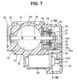
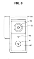
- FIG. 7 and 8 An example of the first embodiment that does not use metal plate 10, and has a throttle body made of resin, is described using Figs. 7 and 8.
- the same reference numerals are given to the same components as those of the first embodiment shown in Figs. 1 and 2.
- one end of the throttle shaft 12 is rotatably supported by throttle body 111 made of a resin via the bearing 15.
- the throttle body 111 holds the other end of the spring 26, the shaft 29 and the motor 40.
- the dimensional accuracy between the throttle shaft 12, shaft 29 or the rotary shaft 1 is much lower than in the first embodiment due to insufficient rigidity of the throttle body 111. Consequently, gear teeth 42a, large-diameter gear teeth 28b, small-diameter gear teeth 28a, or gear teeth 20a may wear during use. This results in torque loss of motor 40 and transmission loss of driving force of motor 40 to throttle valve 13. Further, when dimensional accuracy between throttle shaft 12 and shaft 29 or rotary shaft 41 largely deteriorates, the gear teeth 42a, large-diameter gear teeth 28b, small-diameter gear teeth 28a, or gear teeth 20a lock and the throttle valve 13 cannot be driven.
- the metal plate 10 because of the metal plate 10, one end of the throttle shaft 12 is supported, the other end of the spring 26 and the shaft 29 are fixed, and the motor 40 is held. Consequently, even when the throttle body 11 is made of resin material, the rigidity of the throttle apparatus 1 is enhanced, and high dimensional accuracy among the throttle shaft 12, shaft 29, and rotary shaft 41 can be assured.
- the driving force of the motor 40 can be therefore effectively transmitted to the throttle valve 13 via the rotary shaft 41, gear teeth 42a, large-diameter gear teeth 28b, small-diameter gear teeth 28a, gear teeth 20a, and throttle shaft 12.
- the weight and cost of the throttle apparatus can be reduced.
- the metal plate 10 made of a material having strength higher than the resin material for forming the throttle body 11, the rigidity of the throttle apparatus 1 is enhanced and durability can be therefore improved.
- Figs. 3 and 4 show a second embodiment of the invention.
- the metal plate 10 in the first embodiment shown in Figs. 1 and 2 also serves as a housing of the motor 40, and the same components as those in the first embodiment are designated by the same reference numerals.
- a metal plate 60 As shown in Figs. 3 and 4, a metal plate 60, a holding member, is provided by insertion molding in the throttle body 11 and is made of a material having strength higher than the resin material. Such material may be aluminum, and the throttle body is preferably an integral member containing the housing of the motor 40.
- the metal plate 60 has a supporting hole 60a and a fixing hole 60b. One end of the throttle shaft 12 is supported by the inner wall of the supporting hole 60a via the bearing 15, and the shaft 29 is fixed to the inner wall of the fixing hole 60b.
- the motor 40 is housed and held in the metal plate 60.
- the rigidity of the throttle apparatus is enhanced and high dimensional accuracy among the throttle shaft 12, shaft 29, and rotary shaft 41 is assured.
- the motor 40 is housed in the metal plate 60. Consequently, by allowing the metal plate 60 to serve as the housing of the motor 40, the number of parts is reduced and the number of assembling steps is decreased. Thus, the construction is simplified and the manufacturing cost is reduced.
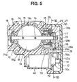
- Figs. 5 and 6 show a third embodiment of the invention.
- the inner wall of the intake path 11a near the throttle valve 13 is formed by the metal plate 10 of the first embodiment shown in Figs. 1 and 2, and the same components as those of the first embodiment are designated by the same reference numerals.
- a metal plate 70 is a holding member provided by insertion molding in throttle body 91 made of a resin.
- Metal plate 70 is made of a higher strength material than the resin material.
- Plate 70 can be aluminum, and is an integral member having a ring portion 71 and a plate portion 72.
- the ring portion 71 is provided on the inner circumference of bore 91a of the throttle body 91 and serves as the inner wall of the intake path 11a near the throttle valve 13.
- the ring portion 71 has supporting holes 70a and 71a.
- One end of the throttle shaft 12 is supported on the inner wall of the supporting hole 70a via the bearing 15, and the other end of the throttle shaft 12 is supported by the inner wall of the supporting hole 71a via the -bearing 16.
- the plate portion 72 has a fixing hole 70b and a holding hole 70c.
- the shaft 29 is fixed on the inner wall of the fixing hole 70b, and the motor 40 is held on the inner wall of the holding hole 70c.
- the rigidity of the throttle apparatus is enhanced and high dimensional accuracy among the throttle shaft 12, shaft 29, and rotary shaft 41 is assured.
- the inner wall of the intake path 11a near the throttle valve 13 is formed by the ring portion 71, so that the throttle shaft 12, shaft 29, and rotary shaft 41 are parallel and held with high precision. Therefore, the driving force of the motor 40 is reliably transmitted to the throttle valve 13 and the controllability of the throttle valve 13 is increased. Further, by integrating the ring portion 71 and the plate portion 72, without increasing the number of parts and the number of assembling steps, the manufacturing cost can be reduced while maintaining simple construction.
- the metal plate is provided by insertion molding in the throttle body.
- part of the metal plate may be exposed to the outside of the throttle body, or the metal plate may be fit to the throttle body.
- the plate may be made of resin provided that the resin has a strength higher than the resin material used for forming the throttle body.
- the plate may also be any suitable hard metal such as magnesium.
- a metal plate (10) is made of a material having strength higher than a resin material for forming a throttle body (11) and is disposed in the throttle body (11).
- the plate supports one end of a throttle shaft (12), fixes a shaft (29), and holds a motor (40).
- the throttle body (11) is made of a resin material, therefore, the rigidity of the throttle apparatus (1) (1) is enhanced and high dimensional accuracy among the throttle shaft (12), the shaft (29), and a rotary shaft (41) can be assured.
Landscapes
- Engineering & Computer Science (AREA)
- Chemical & Material Sciences (AREA)
- Combustion & Propulsion (AREA)
- Mechanical Engineering (AREA)
- General Engineering & Computer Science (AREA)
- Control Of Throttle Valves Provided In The Intake System Or In The Exhaust System (AREA)
Abstract
Description
Claims (13)
- A throttle apparatus (1) for adjusting an air flow rate through an air path formed in an internal combustion engine, said throttle apparatus (1) characterized by:a resin throttle body (11) material having an air path formed therein;a valve member (13) provided in the throttle body (11) that controls an opening angle of the air path;electric driving device (40) housed in the throttle body (11), said electric driving device (40) generating a driving force that drives the valve member (13); anda holding member (10) provided in the throttle body (11) that rotatably supports the valve member (13), said holding member (10) holding the electric driving device, said holding member (10) being made of a material having strength higher than a resin material used for forming the throttle body (11).
- The throttle apparatus (1) according to claim 1, further characterized by:a transmitting device (28) connected to the electric driving device (40), said transmitting device (28) transmitting a driving force from the electric driving device (40) to the valve member (13); anda supporting member fixed to the holding member (10), said supporting member rotatably supporting the transmitting device (28).
- The throttle apparatus (1) according to claim 1 or 2, characterized in that the holding member (10) houses the electric driving device (40).
- The throttle apparatus (1) according to claim 1, 2, or 3, characterized in that an inner wall of the air path near the valve member (13) is formed by the holding member (10).
- A throttle apparatus (1) for adjusting an air flow rate through an air path formed in an internal combustion engine, said throttle apparatus (1)
characterized by:a resin throttle body (11) material and having an air path formed therein;a valve member (13) provided in the throttle body (11) so as to control an opening angle of the air path;an electric driving device (40) housed in the throttle body (11), said electric driving device (40) generating a driving force that drives the valve member (13);a transmitting device (28) connected to the electric driving device (40), said transmitting device (28) transmitting the driving force from the electric driving device (40) to the valve member (13);a supporting member that rotatably supports the transmitting device (28); anda holding member (10) provided in the throttle body (11) that affixes the supporting member and holds the electric driving device (40), said holding member (10) being made of a material having strength higher than a resin material used for forming the throttle body (11). - The throttle apparatus (1) according to claim 5, characterized in that the holding member (10) houses the electric driving device (40).
- The throttle apparatus (1) according to Claim 5, wherein said holding member is made of metal.
- The throttle apparatus (1) according to Claim 5, wherein said holding member is made of magnesium.
- The throttle apparatus (1) according to Claim 1, wherein said holding member is made from magnesium
- The throttle apparatus (1) according to Claim 1, wherein said holding member is made of metal.
- A retaining member for retaining a position between elements of a throttle body, comprising:a plate made of a material, wherein said plate has:a first bore having a diameter sized to support a throttle shaft of a throttle valve;a second bore having a diameter sized to support an electric driving device, a centerline of said second bore being positioned a predetermined distance from a centerline of said first bore; andan outer periphery of said plate sized to fit within a recess of a resin throttle body, said material having a strength higher than that of said resin throttle body.
- The retaining member as claimed in Claim 11, further comprising a transmission device, said transmission device supported by a third aperture in said plate, wherein a centerline of said third aperture is positioned a predetermined distance from said first aperture and said second aperture.
- A retaining member for retaining a position between a throttle shaft, electric driving device, and a transmitting device of a resin throttle body, said retaining member comprising:a plate made of a material having:a first bore with a diameter sized to support a bearing, said bearing having a diameter sized to support a throttle shaft of a throttle valve;a second bore having a diameter sized to support an electric driving device;a third bore having a diameter sized to support a transmission member;wherein centerlines of said first bore, said second bore and said third bore are positioned in said plate at predetermined distances from each other; andwhereby said throttle shaft, said electric driving device and said transmission member are maintained at a predetermined relationship with each other when said plate is assembled in said resin throttle body;an outer periphery of said plate that fits within a recess of said resin throttle body, said material having a strength higher than that of said resin throttle body.
Applications Claiming Priority (4)
| Application Number | Priority Date | Filing Date | Title |
|---|---|---|---|
| JP2000039709 | 2000-02-17 | ||
| JP2000039709 | 2000-02-17 | ||
| JP2001009000A JP2001303983A (en) | 2000-02-17 | 2001-01-17 | Throttle device for internal combustion engine |
| JP2001009000 | 2001-01-17 |
Publications (2)
| Publication Number | Publication Date |
|---|---|
| EP1126147A2 true EP1126147A2 (en) | 2001-08-22 |
| EP1126147A3 EP1126147A3 (en) | 2002-08-14 |
Family
ID=26585568
Family Applications (1)
| Application Number | Title | Priority Date | Filing Date |
|---|---|---|---|
| EP01103743A Withdrawn EP1126147A3 (en) | 2000-02-17 | 2001-02-15 | Throttle apparatus for internal combustion engine |
Country Status (3)
| Country | Link |
|---|---|
| US (1) | US6295968B2 (en) |
| EP (1) | EP1126147A3 (en) |
| JP (1) | JP2001303983A (en) |
Cited By (3)
| Publication number | Priority date | Publication date | Assignee | Title |
|---|---|---|---|---|
| EP1925797A1 (en) * | 2006-11-23 | 2008-05-28 | Robert Bosch Gmbh | Actuating drive for an actuator |
| WO2009024369A1 (en) * | 2007-08-22 | 2009-02-26 | Pierburg Gmbh | Electrical internal combustion engine adjusting arrangement |
| DE102004049451B4 (en) * | 2003-10-31 | 2016-06-23 | Denso Corporation | A throttle control device having an internal support structure and a method of manufacturing a throttle control device |
Families Citing this family (17)
| Publication number | Priority date | Publication date | Assignee | Title |
|---|---|---|---|---|
| US6491019B1 (en) * | 1999-01-29 | 2002-12-10 | Ab Elektronik Gmbh | Angular rotation sensor |
| DE10007611A1 (en) * | 2000-02-18 | 2001-08-23 | Mannesmann Vdo Ag | Throttle body |
| US6508455B2 (en) * | 2000-12-28 | 2003-01-21 | Visteon Global Technologies, Inc. | Electronic throttle body gear train module |
| US6789526B2 (en) * | 2001-02-08 | 2004-09-14 | Denso Corporation | Apparatus for controlling throttle valve and manufacturing method for the same and motor |
| JP2003083095A (en) * | 2001-07-05 | 2003-03-19 | Denso Corp | Engine throttle device |
| US6736368B2 (en) * | 2002-07-22 | 2004-05-18 | Eagle Industry Co., Ltd. | Gate valve |
| JP2004162680A (en) | 2002-11-08 | 2004-06-10 | Aisan Ind Co Ltd | Electric type throttle body |
| JP4055547B2 (en) * | 2002-10-25 | 2008-03-05 | 株式会社デンソー | Electronically controlled throttle control device |
| JP2004263734A (en) * | 2003-02-28 | 2004-09-24 | Denso Corp | Rolling bearing |
| JP4376017B2 (en) * | 2003-08-01 | 2009-12-02 | 株式会社デンソー | Electronically controlled throttle control device |
| JP2005054627A (en) | 2003-08-01 | 2005-03-03 | Denso Corp | Throttle body |
| JP4412963B2 (en) * | 2003-10-10 | 2010-02-10 | 旭有機材工業株式会社 | Plastic parts for valves |
| JP4457038B2 (en) * | 2005-04-14 | 2010-04-28 | 日立オートモティブシステムズ株式会社 | Motor driven throttle control device for internal combustion engine |
| KR102146657B1 (en) | 2017-12-27 | 2020-08-21 | 주식회사 현대케피코 | Throttle valve assembly |
| KR102096245B1 (en) * | 2018-12-21 | 2020-04-03 | 주식회사 현대케피코 | Electronic controlled throttle valve device |
| KR102185008B1 (en) * | 2019-07-22 | 2020-12-01 | (주)현대케피코 | Housing of electronic throttle valve and electronic throttle valve including the same |
| KR102185007B1 (en) * | 2019-11-28 | 2020-12-01 | (주)현대케피코 | Housing of electronic throttle valve and manufacturing method thereof |
Family Cites Families (16)
| Publication number | Priority date | Publication date | Assignee | Title |
|---|---|---|---|---|
| JP2758535B2 (en) * | 1992-07-16 | 1998-05-28 | 株式会社日立製作所 | Electronic throttle control |
| DE4334180A1 (en) * | 1993-10-07 | 1995-04-13 | Bosch Gmbh Robert | Throttling device |
| JPH07324636A (en) * | 1994-04-04 | 1995-12-12 | Nippondenso Co Ltd | Throttle valve control device |
| DE69627506T3 (en) * | 1995-01-17 | 2014-03-06 | Hitachi, Ltd. | Airflow control device |
| JPH1047520A (en) | 1996-07-31 | 1998-02-20 | Toyota Autom Loom Works Ltd | Throttle body |
| EP1512857A3 (en) * | 1996-09-03 | 2011-04-20 | Hitachi Automotive Systems, Ltd. | A throttle valve control device for an internal combustion engine |
| JP3364873B2 (en) * | 1997-03-13 | 2003-01-08 | 株式会社日立ユニシアオートモティブ | Electronically controlled throttle valve device for internal combustion engine |
| JP3361030B2 (en) * | 1997-03-19 | 2003-01-07 | 株式会社日立ユニシアオートモティブ | Electronically controlled throttle valve device for internal combustion engine |
| JP3404254B2 (en) * | 1997-05-07 | 2003-05-06 | 株式会社日立製作所 | Engine throttle device |
| JPH1162637A (en) | 1997-08-26 | 1999-03-05 | Denso Corp | Intake device for internal combustion engine |
| DE19848594C2 (en) * | 1997-10-21 | 2002-11-14 | Hitachi Ltd | Electrically controlled throttle device |
| JPH11132062A (en) | 1997-10-30 | 1999-05-18 | Denso Corp | Throttle device |
| US5979871A (en) * | 1998-03-30 | 1999-11-09 | Ford Motor Company | Clamshell throttle valve assembly |
| US6129071A (en) * | 1998-07-20 | 2000-10-10 | Ford Global Technologies, Inc. | Throttle valve system |
| US6155533C1 (en) * | 1999-01-29 | 2002-07-30 | Visteon Global Tech Inc | Default mechanism for electronic throttle control system |
| JP2000265861A (en) * | 1999-03-15 | 2000-09-26 | Aisan Ind Co Ltd | Intake device for internal combustion engine |
-
2001
- 2001-01-17 JP JP2001009000A patent/JP2001303983A/en not_active Withdrawn
- 2001-02-09 US US09/779,741 patent/US6295968B2/en not_active Expired - Fee Related
- 2001-02-15 EP EP01103743A patent/EP1126147A3/en not_active Withdrawn
Cited By (5)
| Publication number | Priority date | Publication date | Assignee | Title |
|---|---|---|---|---|
| DE102004049451B4 (en) * | 2003-10-31 | 2016-06-23 | Denso Corporation | A throttle control device having an internal support structure and a method of manufacturing a throttle control device |
| EP1925797A1 (en) * | 2006-11-23 | 2008-05-28 | Robert Bosch Gmbh | Actuating drive for an actuator |
| WO2009024369A1 (en) * | 2007-08-22 | 2009-02-26 | Pierburg Gmbh | Electrical internal combustion engine adjusting arrangement |
| US8156922B2 (en) | 2007-08-22 | 2012-04-17 | Pierburg Gmbh | Electrical actuating arrangement for an internal combustion engine |
| CN101802370B (en) * | 2007-08-22 | 2013-10-30 | 皮尔伯格有限责任公司 | Electrical internal combustion engine adjusting arrangement |
Also Published As
| Publication number | Publication date |
|---|---|
| EP1126147A3 (en) | 2002-08-14 |
| US6295968B2 (en) | 2001-10-02 |
| US20010015195A1 (en) | 2001-08-23 |
| JP2001303983A (en) | 2001-10-31 |
Similar Documents
| Publication | Publication Date | Title |
|---|---|---|
| US6295968B2 (en) | Throttle apparatus for internal combustion engine | |
| EP2005031B1 (en) | Actuator with integrated drive mechanism | |
| US5687691A (en) | Throttle device and method for producing a throttle device | |
| EP1170487B1 (en) | Electronic throttle control mechanism with reduced friction and wear | |
| EP1515022A1 (en) | A servo-assisted butterfly valve provided with a flat leaf spring and a spiral spring to establish the limp-home position | |
| EP1099841A2 (en) | Electric throttle control system with two-spring failsafe mechanism | |
| US20050155575A1 (en) | Throttle contol devices | |
| US6279535B1 (en) | Throttle control device | |
| JP2004150324A (en) | Electronically controlled throttle control | |
| EP1948966A1 (en) | Actuator with integrated drive mechanism | |
| US6109240A (en) | Apparatus for controlling a throttle valve electronically in an internal combustion engine | |
| JP2005133655A (en) | Throttle control device for internal combustion engine | |
| EP1515023A1 (en) | An electronically controlled butterfly valve provided with a flat leaf spring and a spiral spring to establish the limp-home position | |
| EP1170486B1 (en) | Electronic throttle control mechanism with integrated modular construction | |
| JP4356610B2 (en) | Intake air amount control device | |
| JP5447266B2 (en) | Electric actuator | |
| JP4831085B2 (en) | Electronic throttle device for internal combustion engines | |
| EP1375869B1 (en) | Throttle device | |
| JPH11173169A (en) | Throttle valve device | |
| JP2007278123A (en) | Throttle valve control device | |
| JP2004162680A (en) | Electric type throttle body | |
| JP5429080B2 (en) | Throttle device | |
| JP2000265861A (en) | Intake device for internal combustion engine | |
| JP2003512571A (en) | Electronic throttle control link device with limp home mechanism | |
| KR101498818B1 (en) | Electronic throttle assembly |
Legal Events
| Date | Code | Title | Description |
|---|---|---|---|
| PUAI | Public reference made under article 153(3) epc to a published international application that has entered the european phase |
Free format text: ORIGINAL CODE: 0009012 |
|
| AK | Designated contracting states |
Kind code of ref document: A2 Designated state(s): AT BE CH CY DE DK ES FI FR GB GR IE IT LI LU MC NL PT SE TR |
|
| AX | Request for extension of the european patent |
Free format text: AL;LT;LV;MK;RO;SI |
|
| PUAL | Search report despatched |
Free format text: ORIGINAL CODE: 0009013 |
|
| AK | Designated contracting states |
Kind code of ref document: A3 Designated state(s): AT BE CH CY DE DK ES FI FR GB GR IE IT LI LU MC NL PT SE TR |
|
| AX | Request for extension of the european patent |
Free format text: AL;LT;LV;MK;RO;SI |
|
| RIC1 | Information provided on ipc code assigned before grant |
Free format text: 7F 02D 11/10 A, 7F 02D 9/10 B |
|
| 17P | Request for examination filed |
Effective date: 20020823 |
|
| AKX | Designation fees paid |
Designated state(s): DE FR GB IT |
|
| GRAP | Despatch of communication of intention to grant a patent |
Free format text: ORIGINAL CODE: EPIDOSNIGR1 |
|
| STAA | Information on the status of an ep patent application or granted ep patent |
Free format text: STATUS: THE APPLICATION IS DEEMED TO BE WITHDRAWN |
|
| 18D | Application deemed to be withdrawn |
Effective date: 20070124 |