EP1126003A1 - Resin bonded abrasive tool - Google Patents
Resin bonded abrasive tool Download PDFInfo
- Publication number
- EP1126003A1 EP1126003A1 EP01103513A EP01103513A EP1126003A1 EP 1126003 A1 EP1126003 A1 EP 1126003A1 EP 01103513 A EP01103513 A EP 01103513A EP 01103513 A EP01103513 A EP 01103513A EP 1126003 A1 EP1126003 A1 EP 1126003A1
- Authority
- EP
- European Patent Office
- Prior art keywords
- resin
- amorphous carbon
- abrasive tool
- resin bonded
- bonded abrasive
- Prior art date
- Legal status (The legal status is an assumption and is not a legal conclusion. Google has not performed a legal analysis and makes no representation as to the accuracy of the status listed.)
- Granted
Links
- 229920005989 resin Polymers 0.000 title claims abstract description 219
- 239000011347 resin Substances 0.000 title claims abstract description 219
- 239000002245 particle Substances 0.000 claims abstract description 123
- 229910003481 amorphous carbon Inorganic materials 0.000 claims abstract description 112
- 239000011230 binding agent Substances 0.000 claims abstract description 79
- 239000000945 filler Substances 0.000 claims abstract description 60
- 229910052751 metal Inorganic materials 0.000 claims abstract description 21
- 239000002184 metal Substances 0.000 claims abstract description 21
- 239000011521 glass Substances 0.000 claims abstract description 18
- 229910052802 copper Inorganic materials 0.000 claims abstract description 6
- OKTJSMMVPCPJKN-UHFFFAOYSA-N Carbon Chemical group [C] OKTJSMMVPCPJKN-UHFFFAOYSA-N 0.000 claims description 20
- 229910002804 graphite Inorganic materials 0.000 claims description 17
- 239000010439 graphite Substances 0.000 claims description 17
- 239000011148 porous material Substances 0.000 claims description 12
- VYPSYNLAJGMNEJ-UHFFFAOYSA-N Silicium dioxide Chemical compound O=[Si]=O VYPSYNLAJGMNEJ-UHFFFAOYSA-N 0.000 claims description 8
- 229910052759 nickel Inorganic materials 0.000 claims description 6
- 229910052709 silver Inorganic materials 0.000 claims description 6
- 229910052681 coesite Inorganic materials 0.000 claims description 4
- 229910052906 cristobalite Inorganic materials 0.000 claims description 4
- 229910003465 moissanite Inorganic materials 0.000 claims description 4
- 229910010271 silicon carbide Inorganic materials 0.000 claims description 4
- 239000000377 silicon dioxide Substances 0.000 claims description 4
- 229910052682 stishovite Inorganic materials 0.000 claims description 4
- 229910052905 tridymite Inorganic materials 0.000 claims description 4
- 239000000956 alloy Substances 0.000 claims description 3
- 229910045601 alloy Inorganic materials 0.000 claims description 3
- 150000002739 metals Chemical class 0.000 claims 1
- 239000010410 layer Substances 0.000 abstract description 72
- 239000005011 phenolic resin Substances 0.000 abstract description 10
- 239000011247 coating layer Substances 0.000 abstract description 7
- 229910003460 diamond Inorganic materials 0.000 abstract description 7
- 239000010432 diamond Substances 0.000 abstract description 7
- 238000000227 grinding Methods 0.000 description 90
- 230000000052 comparative effect Effects 0.000 description 37
- 239000000463 material Substances 0.000 description 21
- 230000003247 decreasing effect Effects 0.000 description 16
- 230000000694 effects Effects 0.000 description 15
- 239000006061 abrasive grain Substances 0.000 description 11
- 230000001965 increasing effect Effects 0.000 description 10
- 239000000314 lubricant Substances 0.000 description 10
- 238000005520 cutting process Methods 0.000 description 9
- 230000007423 decrease Effects 0.000 description 9
- 238000009826 distribution Methods 0.000 description 7
- 238000003754 machining Methods 0.000 description 7
- 239000007787 solid Substances 0.000 description 6
- WUKWITHWXAAZEY-UHFFFAOYSA-L calcium difluoride Chemical compound [F-].[F-].[Ca+2] WUKWITHWXAAZEY-UHFFFAOYSA-L 0.000 description 5
- 229910001634 calcium fluoride Inorganic materials 0.000 description 5
- 238000012986 modification Methods 0.000 description 5
- 230000004048 modification Effects 0.000 description 5
- 230000003746 surface roughness Effects 0.000 description 5
- KXGFMDJXCMQABM-UHFFFAOYSA-N 2-methoxy-6-methylphenol Chemical compound [CH]OC1=CC=CC([CH])=C1O KXGFMDJXCMQABM-UHFFFAOYSA-N 0.000 description 4
- 229910052799 carbon Inorganic materials 0.000 description 4
- 229920001568 phenolic resin Polymers 0.000 description 4
- 238000005452 bending Methods 0.000 description 3
- 239000013078 crystal Substances 0.000 description 3
- 239000000203 mixture Substances 0.000 description 3
- 235000012239 silicon dioxide Nutrition 0.000 description 3
- 239000004604 Blowing Agent Substances 0.000 description 2
- 230000006378 damage Effects 0.000 description 2
- 239000007788 liquid Substances 0.000 description 2
- XUIMIQQOPSSXEZ-UHFFFAOYSA-N Silicon Chemical compound [Si] XUIMIQQOPSSXEZ-UHFFFAOYSA-N 0.000 description 1
- 239000010953 base metal Substances 0.000 description 1
- 230000015556 catabolic process Effects 0.000 description 1
- 238000009833 condensation Methods 0.000 description 1
- 230000005494 condensation Effects 0.000 description 1
- 238000006731 degradation reaction Methods 0.000 description 1
- 230000006866 deterioration Effects 0.000 description 1
- 238000005516 engineering process Methods 0.000 description 1
- 239000003822 epoxy resin Substances 0.000 description 1
- 125000001153 fluoro group Chemical group F* 0.000 description 1
- 239000004088 foaming agent Substances 0.000 description 1
- 229910021397 glassy carbon Inorganic materials 0.000 description 1
- -1 hBN Chemical compound 0.000 description 1
- 230000001939 inductive effect Effects 0.000 description 1
- 238000012423 maintenance Methods 0.000 description 1
- 238000004519 manufacturing process Methods 0.000 description 1
- 238000005259 measurement Methods 0.000 description 1
- 238000000034 method Methods 0.000 description 1
- 229920000647 polyepoxide Polymers 0.000 description 1
- 239000000843 powder Substances 0.000 description 1
- 230000002265 prevention Effects 0.000 description 1
- 230000002035 prolonged effect Effects 0.000 description 1
- 239000002994 raw material Substances 0.000 description 1
- 239000004065 semiconductor Substances 0.000 description 1
- 229910052710 silicon Inorganic materials 0.000 description 1
- 239000010703 silicon Substances 0.000 description 1
- 230000002195 synergetic effect Effects 0.000 description 1
- 229920001187 thermosetting polymer Polymers 0.000 description 1
- 239000002699 waste material Substances 0.000 description 1
Images



Classifications
-
- C—CHEMISTRY; METALLURGY
- C09—DYES; PAINTS; POLISHES; NATURAL RESINS; ADHESIVES; COMPOSITIONS NOT OTHERWISE PROVIDED FOR; APPLICATIONS OF MATERIALS NOT OTHERWISE PROVIDED FOR
- C09K—MATERIALS FOR MISCELLANEOUS APPLICATIONS, NOT PROVIDED FOR ELSEWHERE
- C09K3/00—Materials not provided for elsewhere
- C09K3/14—Anti-slip materials; Abrasives
- C09K3/1436—Composite particles, e.g. coated particles
- C09K3/1445—Composite particles, e.g. coated particles the coating consisting exclusively of metals
-
- B—PERFORMING OPERATIONS; TRANSPORTING
- B24—GRINDING; POLISHING
- B24D—TOOLS FOR GRINDING, BUFFING OR SHARPENING
- B24D3/00—Physical features of abrasive bodies, or sheets, e.g. abrasive surfaces of special nature; Abrasive bodies or sheets characterised by their constituents
- B24D3/02—Physical features of abrasive bodies, or sheets, e.g. abrasive surfaces of special nature; Abrasive bodies or sheets characterised by their constituents the constituent being used as bonding agent
- B24D3/20—Physical features of abrasive bodies, or sheets, e.g. abrasive surfaces of special nature; Abrasive bodies or sheets characterised by their constituents the constituent being used as bonding agent and being essentially organic
- B24D3/28—Resins or natural or synthetic macromolecular compounds
-
- B—PERFORMING OPERATIONS; TRANSPORTING
- B24—GRINDING; POLISHING
- B24D—TOOLS FOR GRINDING, BUFFING OR SHARPENING
- B24D3/00—Physical features of abrasive bodies, or sheets, e.g. abrasive surfaces of special nature; Abrasive bodies or sheets characterised by their constituents
- B24D3/34—Physical features of abrasive bodies, or sheets, e.g. abrasive surfaces of special nature; Abrasive bodies or sheets characterised by their constituents characterised by additives enhancing special physical properties, e.g. wear resistance, electric conductivity, self-cleaning properties
- B24D3/342—Physical features of abrasive bodies, or sheets, e.g. abrasive surfaces of special nature; Abrasive bodies or sheets characterised by their constituents characterised by additives enhancing special physical properties, e.g. wear resistance, electric conductivity, self-cleaning properties incorporated in the bonding agent
- B24D3/344—Physical features of abrasive bodies, or sheets, e.g. abrasive surfaces of special nature; Abrasive bodies or sheets characterised by their constituents characterised by additives enhancing special physical properties, e.g. wear resistance, electric conductivity, self-cleaning properties incorporated in the bonding agent the bonding agent being organic
Definitions
- This invention relates to the resin bonded abrasive tool using for particularly miller grinding of hard and brittle materials for example.
- the disclosure of Japanese Application No. H11-230909 , H11-246748 ,and 2000-038653 is hereby incorporated by reference into the present application .
- the resin bonded abrasive tool is produced by the following method.
- the raw powders of thermosetting resin such as, for example, an epoxy resin and phenol resin are mixed with the super abrasive grains of a diamond and CBN etc. , and is molded independently, or with the base metal if needed, after that, it is pressed and sintered.
- the resin bonded abrasive tool formed the super abrasive grains layer is produced.
- the resin bonded phase holding super abrasive grains is crushed or worn out, and super abrasive grains drop out rather than the sharpness falls by the wear in a tip of the super abrasive grain, because, in resin bonded tool, the resin bonded phase holding the super abrasive grains is comparatively elastic and brittle.
- the resin bonded tool in which the solid lubricant, such as hBN and graphite for example, as filler is dispersed inside of the resin bonded phase in order to control the frictional heat generated by grinding resistance .
- the solid lubricant such as hBN and graphite for example
- This invention aims at offering resin bonded abrasive tool which can raise wear resistance and reduce the grinding resistance .
- the resin bonded abrasive tool of this invention is characterized by distributing amorphous carbon in the above stated resin binder phase in resin bonded abrasive tool which comes to distribute super abrasive particle in resin binder phase .
- the amorphous carbon (herein after, same to glassy carbon ) has the characteristics that the bending strength is at about 16 kg/mm2 and the value is large about 5 times to graphite ( crystal carbon ) ,and the compressive strength is at about 120 kg / mm2 and the value is about large about 20 times to graphite ,and the modulus of elasticity is at about 3 times to graphite ,and the shoa hardness Hs is at about 110 and the value is about 3 times to graphite .
- the binder phase of resin bonded abrasive tool is made , for example, from phenol resin, the modulus of elasticity of the phenol resin is at about 7 ⁇ 102 kg / mm2, it can raise the rate of modulus of elasticity of abrasive particle layer of resin bonded abrasive tool by adding and distributing amorphous carbon in resin binder phase of resin bonded abrasive tool .
- the compressive rigidity of abrasive particle layer can be raised, the abrasive particle layer can carry out compressive deformation by grinding resistance at the time of grinding machining , or it can prevent that the super abrasive particle is buried into resin binder phase even if it is the case where the super abrasive particle projects from the surface of abrasive particle layer and is made into the cutting tooth of resin bonded abrasive tool and is received the grinding resistance , the mechanical strength of abrasive particle layer holding super abrasive particle can be raised .
- the amorphous carbon distributed in resin binder phase acts as lubricant, can reduce the grinding resistance between work materials, can control the generation of grinding heat , in addition, for example, it can control more effectively the deformation of resin bonded abrasive tool, or the wear of the tool because the hardness , compressive strength and bending strength of amorphous carbon is large compared with solid lubricant such as graphite .
- the resin bonded abrasive tool in this invention has the characteristics that the above mentioned amorphous carbon is the shape of spherical type.
- resin bonded abrasive tool it can be raised the compressive strength of resin binder phase by the spherical amorphous carbon, and also possible to relieve the stress which acts to the abrasive particle layer at the time of grinding machining .
- the frictional resistance is small and the generation of frictional heat is suppressed small even if the friction with the work materials arises .
- the resin binder phase which holds spherical amorphous carbon on the surface of abrasive particle layer is worn out and approximately half grade of the whole volume of the spherical amorphous carbon comes to project from the surface of abrasive particle layer , this amorphous carbon will be omitted from the surface of abrasive particle layer , and a tip pocket will be formed in the position where the amorphous carbon was held .
- the holding force by resin binder phase is decreased and the omission from resin binder phase are promoted by that the amorphous carbon is spherical.
- the discharge ability of scraps improves by that the grinding liquid is introduced at the time of grinding machining or grinding waste etc. enters into the formed tip pockets .
- the amorphous carbon is spherical, the compressive strength is high compared with non uniform type, the grinding load and the deformation by grinding can be controlled , or it can prevent effectively burying into the resin binder phase of super abrasive particle which exists in the outside surface. Furthermore , the mobility and formability of raw materials can be raised in case that the abrasive particle layer is formed . Furthermore, the resin bonded abrasive tool has the characteristics that the above mentioned amorphous carbon is non uniform shape .
- the holding force can be raised by using the amorphous carbon of non uniform shape.
- the resin bonded abrasive tool in this invention has the characteristics that the amorphous carbon of the above mentioned non uniform shape is by coming to grind spherical amorphous carbon .
- the minute and spherical amorphous carbon has the problem that the manufacture is difficult and moreover tends to drop out from resin binder phase
- the non uniform shape amorphous carbon which has a particle size distribution which is shown in Figure 7 can be obtained easily by crushing the spherical amorphous carbon against that the mean particle diameter about 20 ⁇ 30 ⁇ m shown in Table 1 and Figure 10 is general , the holding force by resin binder phase can be raised and the wear resistance of resin bonded abrasive tool can be raised .
- the spherical amorphous carbon is the most precise and the precise and minute shape amorphous carbon can be obtained by crushing the spherical amorphous carbon .
- the resin bonded abrasive tool in this invention has the characteristics that the particle diameter of above mentioned non uniform shape amorphous carbon is 20 ⁇ m or less .
- the contact length of work material and resin may increase and the grinding resistance may increase , however, by setting particle diameter to 20 ⁇ m or less, the amorphous carbon is arranged in a narrow pitch and the contact of the work material and resin is controlled, as the results, the grinding resistance is reduced and the generation of grinding heat is controlled , and also the wear resistance of resin bonded abrasive tool can be raised .
- the resin bonded abrasive tool of this invention has a characteristics that the metal of Cu or Ag or Ni or Co or the alloy including these metal is coated on a surface of above mentioned amorphous carbon .
- the amorphous carbon coated by metal which is a high thermal conductivity is distributed in abrasive particle layer , as the results, the thermal conductivity of abrasive particle layer can be raised , the heat which occurs at the time of grinding machining can be made to be able to emit quickly from abrasive particle layer, and the deterioration of resin binder phase can be prevented .
- the resin bonded abrasive tool in this invention has a characteristics that the volume ratio of above mentioned amorphous carbon to the above mentioned resin binder phase except super abrasive particle is 5 ⁇ 60 vol % .
- the amorphous carbon is produced by baking phenol formaldehyde resin at 600 °C ⁇ 3000 ° C , if it is baked below 600 ° C, the shore hardness becomes less than 100, and since the hardness of amorphous carbon is small, the deformation of the resin bonded abrasive tool and inclination wear can not be controlled and also since the lubricity is low, the generation of grinding heat by the decreasing grinding resistance between work materials can not be controlled .
- hardness is as high as which was baked at high temperature, and it serves as amorphous carbon excellent in lubricity .
- the resin bonded abrasive tool in this invention has a characteristics that the wear resistant filler more than a kind at least in the above mentioned resin binder phase.
- the resin bonded abrasive tool in this invention has a characteristics that the above mentioned wear resistant filler includes more than a kind at least of SiC, SiO2, Ag, Cu, Ni .
- the wear of abrasive particle layer is controlled much more, and can be controlled prolongation of abrasive tool life .
- the resin bonded abrasive tool in this invention ha a characteristics that the lubricative filler more than a kind at least is distributed in resin binder phase .
- the resin bonded abrasive tool since the lubricative filler is distributed, the grinding resistance is reduced , and the grinding ratio can be raised without increasing grinding resistance by distributing amorphous carbon to resin bonded abrasive tool with the sufficient sharpness planned so that the grinding of the work material by super abrasive particle could be smoothly performed at the time of grinding . Furthermore, the resin bonded abrasive tool in this invention has a characteristics that the above mentioned lubricative filler includes more than a kind at least of graphite , hBN, fluoro -resin .
- the resin bonded abrasive tool in this invention has a characteristics that preferably pores are included 5 ⁇ 40 vol % in resin binder phase .
- the pores can be formed by adding a blowing agent to the phenol-formaldehyde resin. During baking the phenol-formaldehyde resin, the blowing agent decomposes evolving gas.
- the pores have effects such as inducing the grinding liquid on a surface of abrasive particle layer , and improvement in the discharge ability of tip, and prevention of condensation with work material, as the results, by the synergistic effect with the amorphous carbon, reduces the grinding resistance much more and has an remarkable effect in an improvement of the grounded surface roughness of work material.
- the resin bonded abrasive tool in this invention has a characteristics that the hollow glass is distributed in resin binder phase .
- the part of the hollow glass which exposed from the surface of the abrasive particle layer is destroyed by the contact with work material at a time of grinding , and as the results, the tip pocket is formed and the discharge ability of the tip can be improved , and in addition, the strength of the abrasive layer that was decreased by the addition of hollow glass can be raised by the addition of amorphous carbon simultaneously , it can be possible to obtain the resin bonded abrasive tool excellent to the sharpness .
- Table 1 is a particle size distribution of spherical amorphous carbon .
- Table 2 is a particle size distribution of non- uniform shape amorphous carbon .
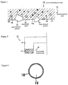
- Figure 1 is an enlarged sectional view of the principal part shown as one example of resin bonded abrasive tool concerning this invention .
- Figure 2 is a part of the sectional view of cup type abrasive tool in which an abrasive particle layer is equipped to the base plate shown in Figure 1.
- Figure 3 is a sectional view of amorphous carbon which has the metal coating layer shown in Figure 1 .
- Figure 4 is an enlarged sectional view of the principal part shown as the 1st modification of resin bonded abrasive tool of this example .
- Figure 5 is an enlarged sectional view of the principal part shown as the 2nd modification of resin bonded abrasive tool of this example .
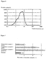
- Figure 6 is the particle size distribution of the non- uniform shape amorphous carbon which forms the filler shown in Figure 5 .
- Figure 7 is the wear ratio of resin bonded abrasive tool by the case of the example in this invention and comparative example 1, 2, 3 ..
- Figure 8 is the wear ratio of resin bonded abrasive tool by the case of the example in this invention and the comparative example 1,4.
- Figure 9 is a sectional view shown about the conventional resin bonded abrasive tool.
- Figure 10 is a particle size distribution of the spherical amorphous carbon used as filler for resin bonded abrasive tool by one example of conventional technology .
- Figure 1 is an enlarged sectional view of a principal part of one example of resin bonded abrasive tool 10 concerning to this invention
- Figure 2 is a sectional view of a part of cup type abrasive tool 12 in which the abrasive particle layer 11 is equipped with the base plate shown in Figure 1
- Figure 3 is a sectional view of an amorphous carbon 19 which has the metal coating layer 18 shown in Figure 1 .
- Resin bonded abrasive tool 10 by the example in this invention is , for example , the abrasive tool using for miller grinding of hard and brittle material, and the abrasive particle layer may be fixed to the tip part of almost ring like of the base plate 13 in cup type abrasive tool 12 shown in Figure 2 for example and the abrasive tool may be constituted by only abrasive particle layer 11 without forming base plate 13 .
- the abrasive particle layer 11 is equipped with resin binder phase 14 which consists from heat-hardening resin such as phenol resin etc., for example, and super abrasive particle 15 of diamond ( or cBN etc. ) which is distributed in this resin binder phase 14 .
- resin binder phase 14 which consists from heat-hardening resin such as phenol resin etc., for example, and super abrasive particle 15 of diamond ( or cBN etc. ) which is distributed in this resin binder phase 14 .
- wear resistant filler 16 and hollow glass 17 and amorphous carbon 19 that has the metal coating layer 18 are distributed in resin binder phase 14 respectively .
- the wear resistant filler 16 is not particularly limited , it is desirable to consists of hard filler of SiC , SiO2, Ag, Cu , Ni which is more than a kind at least, and it is set to SiC ,for example .
- it consists of the metal coating layer 18 on a surface of amorphous carbon 19 , this metal coating layer 18 is consisted from the metal of either of Cu , Ag, Ni, Co or the metal including these alloy , and it is referred to as Cu.
- the amorphous carbon 19 is spherical , for example, and although the particle diameter is not particularly limited , the particle diameter is set preferably in the range of 1 / 10 ⁇ 2 of the particle diameter of super abrasive particle 15 .
- the particle diameter of amorphous carbon 19 is less than 1 / 10 of the particle diameter of super abrasive particle 15 , the effect that decrease the grinding resistance and control the generation of grinding heat and also the effect that increase the wear resistance are weak, conversely , if it is more than 2 times of the particle diameter of super abrasive particle 15, the distributed pitch of amorphous carbon19 will be extended , and the contact length between work material and resin binder phase 14 will be increased, and the increasing of grinding resistance will be brought .
- the total amount of amorphous carbon 19 is made into 5 ⁇ 60 vol % by the volume ratio of resin binder phase 14 except super abrasive particle 15 of abrasive particle layer 11 .
- the quantity of amorphous carbon 19 is less than 5 vol % , the effect which include amorphous carbon 19 , for example, the decreasing of grinding heat and the increasing of wear resistance are not enough . Moreover, if the quantity of amorphous carbon 19 exceeds 60 vol % , the rate of resin binder phase 14 occupied in abrasive particle layer 11 will fall, as the results, the strength of abrasive particle layer 11 falls sharply and wear resistance of abrasive particle layer 11 drops .
- amorphous carbon 19 is produced by baking of phenol- formaldehyde resin at the temperature of 600 °C ⁇ 3000 ° C .
- the baking temperature is under than 600 ° C , the shore hardness Hs becomes less than 100, and the amorphous carbon 19 baked at more high temperature has higher hardness and it is excellent to lubricity , preferably, the baking temperature is more than 700 ° C, in that case, it can be possible to get amorphous carbon 19 which the shore hardness Hs is 100 ⁇ 120.
- the amorphous carbon 19 has the higher elastic modulus than that of phenol resin, for example, which forms resin binder phase 14, therefore, it can be raised the elastic modulus of abrasive particle layer 11, and also it can be raised compressive rigidity of abrasive particle layer 11, and it can be raised the mechanical strength of abrasive particle layer 14 which hold the super abrasive particle 15 .
- the amorphous carbon 19 is spherical shape , it can be relieved the stress which acts to the abrasive particle layer 11 . Furthermore , adding that the amorphous carbon 19 acts as lubricant and decrease the grinding resistance between works , as the results, control the generation of grinding heat , for example, it can be efficiently control the deformation of resin bonded abrasive tool 10 and partial wear as the hardness and compressive strength , bending strength etc. is higher than that of solid lubricants such as graphite for example etc.
- the spherical amorphous carbon 19 which exposed from the surface of abrasive particle layer 11 carries out point contact with grinding surface of work, even if the friction with work is occurred , the wear resistance is small and the generation of frictional heat is suppressed small . Furthermore, for example, comparing to the non-uniform type lubricant which unevenness is formed on a outer surface , the holding force by resin binder phase 14 is decreased, as the results, the omission from resin binder phase 14 are promoted , and the tip pocket 14a is formed , and the discharge ability of chip can be raised . Moreover , as the amorphous carbon 19 which is coated by metal such as Cu etc.
- amorphous carbon 19 is made into the range of 5 ⁇ 60 vol % in a volume ratio of resin binder phase 14 except super abrasive particle 15 of abrasive particle layer 11, it can be prevent to become not enough the effect of decreasing of grinding heat and increasing of wear resistance as in case of below 5 vol % and to be occurred the fault which the wear resistance of abrasive particle layer 11 by decreasing sharply of the strength of abrasive particle layer 11 as in case of exceed 60 vol % .
- wear resistant filler 16 is distributed in resin binder phase 14, but it may not be limited to this, as the enlarged sectional view of a principal part of resin bonded abrasive tool 20 regarding to 1 st modification of this example is shown in Figure 4, the lubricative filler 22 and hollow glass 17 and amorphous carbon 19 having metal coated layer 18 are distributed in a resin binder phase 14 .
- the lubricative filler 22 is not especially limited , but more than a kind of filler of graphite ,and hBN ,and fluoro-resin is desirable, and for example, it considers as graphite .
- the grinding resistance is reduced by lubricative filler 22 distributed in resin binder phase 14 and the resin bonded abrasive tool 20 has excellent sharpness that is planned smoothly the grinding of work by super abrasive particle 15 in a time of grinding.
- the amorphous carbon 19 is also added , it can be raised the grinding ratio without increasing of grinding resistance .
- the strength of abrasive particle layer 21 which has decreased by the addition of hollow glass 17 can be raised by amorphous carbon 19 , as the results, it can be possible to obtain resin bonded abrasive tool 20 which is excellent in sharpness and also is improved in the strength of abrasive tool , particularly , in compressive strength .
- hollow glass 17 and wear resistant filler 16 or lubricative filler 22 are distributed in a resin binder phase 14, it may not be limited to this, hollow glass 17 and wear resistant filler 16 and lubricative filler 22 may be omitted .
- metal coated layer 18 on a surface of amorphous carbon 19 is formed , it may not be limited to this, metal coating layer 18 may be omitted .
- the hollow glass 17 is distributed in a resin binder phase 14 , it may not be limited to this , the pore of 5 ⁇ 40 vol % in spite of hollow glass may be contained . Inthis case , the elasticity of abrasive particle layer 11, 21 can be raised , and it has a remarkable effect in an improvement of surface roughness in grinding of work .
- the pore is less than 5 vol % , the effect mentioned above is weak , conversely , in case that the pore exceed 40 vol % , the strength of abrasive particle layer will decrease .
- the results which grinding resistance and grinding ratio measured to each of this resin bonded abrasive tool in this invention and one example in conventional tool are described.
- the super abrasive particle of diamond 15 is distributed in a resin binder phase 14 which consist from heat hardenable resin such as phenol resin etc.
- This abrasive tool is called as 1st comparative example .
- the 1st example is the resin bonded abrasive tool that the amorphous carbon 19 is distributed in a resin binder phase 14 of resin bonded abrasive tool which is the 1st comparative example .
- the cutting resistance in the 1st example decreased to 1 / 2 of that in the 1st comparative example .
- the grinding ratio in the 1st example improved 50 % of that in the 1st comparative example .
- the 2nd comparative example is a resin bonded abrasive tool that the graphite as the lubricative filler 22 is distributed in a resin binder phase 14 of the resin bonded abrasive tool in 1st comparative example.
- the 2nd example is a resin bonded abrasive tool that amorphous carbon 19 is distributed in a resin binder phase 14 of resin bonded abrasive tool in 2nd comparative example .
- the cutting resistance in 2nd example became almost equivalent to that of 2nd comparative example , and the grinding ratio in 2nd example improved twice than that of 2nd comparative example , and also the maintenance nature of resin bonded abrasive tool improved .
- the 3 rd comparative example is a resin bonded abrasive tool that the hollow glass 17 is distributed in a resin binder phase 14 of the resin bonded abrasive tool in 2 nd comparative example .
- the 3 rd example is a resin bonded abrasive tool that the 1 /2 ⁇ 3 / 4 of the added content of graphite which is added as the lubricative filler 22 is distributed in a resin binder phase 14 of a resin bonded abrasive tool in the 3 rd comparative example is changed to amorphous carbon 19 .
- the strength of abrasive tool in3 rd comparative example is too mush weak and is not used in practically , however, in the 3 rd example , the strength of abrasive tool ,particularly, compressive strength were able to improve and the resin bonded abrasive tool excellent to sharpness was able to be obtained .
- the 4th comparative example is a resin bonded abrasive tool that SiC as wear resistant filler 16 is distributed in a resin binder phase 14 of resin bonded abrasive tool in the 1st comparative example .
- the 4 th example is a resin bonded abrasive tool that amorphous carbon 19 is distributed in a resin binder phase 14 of a resin bonded abrasive tool in this 4 th comparative example , the cutting resistance in this 4th example became to 1 /2 of that of 4th comparative example , and cutting ratio in 4th example is almost equivalent to that of 4th comparative example .
- the 5th comparative example is a resin bonded abrasive tool that SiC and Cu as the wear resistant filler 16 is distributed in resin binder phase 14 of resin bonded abrasive tool in the 1st comparative example .
- the 5th example is a resin bonded abrasive tool that the amorphous carbon 19 is distributed in a resin binder phase 14 of a resin bonded abrasive tool in the 5th comparative example , the cutting resistance in 5th example became to 2 / 5 of that in 5th comparative example , and the grinding ratio was almost equivalent .
- the 6th comparative example is a resin bonded abrasive tool that the hollow glass 17 as pore is distributed in a resin binder phase 14 of resin bonded abrasive tool in4th comparative example .
- the 6th example is a resin bonded abrasive tool that the amorphous carbon 19 is distributed in a resin binder phase 14 of a resin bonded abrasive tool in this 6th comparative example, the cutting resistance in the 6 th example became to 3 / 5 of that in the 6th comparative example , and the grinding ratio was almost equivalent .
- the 7th example is a resin bonded abrasive tool that the pore is formed by using the foaming agent etc. in forming of resin binder phase 14 in spite of the hollow glass 17 in resin bonded abrasive tool in 6th example .
- the surface roughness in the surface of grinding in 7th example was improved 10 % compared to that in 6 the example , and the surface roughness in 7 th example was improved 30 % of that in 6th comparative example .
- From the results mentioned above by distributing the amorphous carbon 19 in a resin binder phase 14 , it can be possible to decrease the cutting resistance , and it can be possible to improve the grinding ratio without increasing the grinding resistance for the resin bonded abrasive tool which is excellent in sharpness , on the other hand, it can check that grinding resistance can be reduced without reducing a grinding ratio for a resin bonded abrasive tool which the life of abrasive tool is long .
- it explains about a resin bonded abrasive tool 30 by the 2nd modification of this example referring to an appended drawings .
- FIG. 5 is enlarged sectional view of a principal part showing resin bonded abrasive tool 30 by 2nd modification in this example and Figure 6 is a particle diameter distribution of non -uniform amorphous carbon which is a filler shown in Figure 5 , and Table 2 is a particle distribution of non-uniform amorphous carbon shown in Figure 6 .
- This resin bonded abrasive tool 30 for example, is formed as cup type abrasive tool for miller grinding of hard and brittle materials , the abrasive particle layer 31 is constructed from a resin binder phase 14 and a super abrasive particle 15 of diamond (or cBN etc. ) distributed in this resin binder phase 14, and also amorphous carbon as filler 36 is distributed in a resin binder phase 14 .
- the filler 36 including resin binder phase 14 for example, consist from non-uniform shape amorphous carbon, for example, as shown in Table 1 and in Figure 10 , it comes to grind practicaly spherical amorphous carbon which the particle diameter is about 20 ⁇ 30 ⁇ m.
- the particle diameter of non-uniform shape amorphous carbon as the filler 36 is made preferably as 20 ⁇ m or less , average particle diameter is made preferably as 4.0 ⁇ m.
- the total amount of filler 36 is made into 5 ⁇ 60 vol % by the volume ratio of resin binder phase 14 except super abrasive particle 15 of abrasive particle layer 31 for example .
- the quantity of filler 36 when the quantity of filler 36 is less than 5 vol % , the effect by containing the filler 36 , for example, the reducing of grinding heat by grinding resistance and the increasing of wear resistance are not enough . Moreover, if the quantity of filler 36 exceeds 60 vol % ,the rate of resin binder phase 14 occupied in abrasive particle layer 31 will fall, and the strength of abrasive particle layer 31 falls sharply , the wear resistance of abrasive particle layer 31 falls.
- the non-uniform amorphous carbon is distributed in resin binder phase 14 of abrasive particle layer 31 as filler 36.
- This filler 36 is formed by crushing prcticaly spherical amorphous carbon which the particle diameter is 20 ⁇ 30 ⁇ m , the particle diameter is preferably set to 20 ⁇ m or less. Therefore , the affinity with resin binder phase 14 is high , and the residual ability within abrasive particle layer 31is high.
- the frictional resistance between working face in a time of grinding machining and the surface of abrasive particle layer 31 can be suppressed , the lubricity the resin binder phase 14 for work material will be secured , and the rise of grinding heat can be controlled , and also the wear resistance of abrasive particle layer 31 can be raised .
- the amorphous carbon is the most minute at the spherical shape ,and the minute and small and non-uniform shape amorphous carbon can be obtained by crushing this spherical shape amorphous carbon .
- the CaF2 which the mean particle diameter is about 2 ⁇ m as the filler 36 in the comparative example 1, the CaF2 which the mean particle diameter is about 2 ⁇ m as the filler 36 .
- the hBN which the mean particle diameter is about 3 ⁇ m was used as filler
- the graphite (crystal carbon)which the mean particle diameter is about 7 ⁇ m was used as filler .
- the spherical shape amorphous carbon which the mean particle diameter is about 20 ⁇ 30 ⁇ m was used as filler .
- the non-uniform shape amorphous carbon by crushing spherical amorphous carbon of comparative example 4 which the mean particle diameter is 20 ⁇ m or less was used as filler .
- the amount of wear of resin bonded abrasive tool 30 at the time of performing the miller grinding of silicon wafer was measured about the comparative example 1, 2, 3, 4 and the example.
- the measured results is shown in Figure 7 and Figure 8 .
- the measurement results of the wear ratio to CaF2 was shown about the comparative example 2, 3, 4 and the example as that the amount of wear in CaF2 of comparative example 1 is 1 .
- the wear resistance of resin bonded abrasive tool 30 can be raised by using the non-uniform shape amorphous carbon compared with the case where CaF2, hBN, Graphite (crystal carbon ) was used as filler .
- the wear resistance of resin bonded abrasive tool 30 can be raised by using the non-uniform shape amorphous carbon which the mean particle diameter is 20 ⁇ m or less obtained by crushing the spherical shape amorphous carbon compared with the case where the spherical shape amorphous carbon which the mean particle diameter is about 20 ⁇ 30 ⁇ m as filler .
Landscapes
- Chemical & Material Sciences (AREA)
- Engineering & Computer Science (AREA)
- Mechanical Engineering (AREA)
- Composite Materials (AREA)
- Materials Engineering (AREA)
- Organic Chemistry (AREA)
- Polishing Bodies And Polishing Tools (AREA)
Abstract
Description
- This invention relates to the resin bonded abrasive tool using for particularly miller grinding of hard and brittle materials for example. The disclosure of Japanese Application No. H11-230909 , H11-246748 ,and 2000-038653 is hereby incorporated by reference into the present application .
- The resin bonded abrasive tool is produced by the following method. The raw powders of thermosetting resin, such as, for example, an epoxy resin and phenol resin are mixed with the super abrasive grains of a diamond and CBN etc. , and is molded independently, or with the base metal if needed, after that, it is pressed and sintered. As the results, the resin bonded abrasive tool formed the super abrasive grains layer is produced.
- When the grinding is performed to comparatively hard work materials, the resin bonded phase holding super abrasive grains is crushed or worn out, and super abrasive grains drop out rather than the sharpness falls by the wear in a tip of the super abrasive grain, because, in resin bonded tool, the resin bonded phase holding the super abrasive grains is comparatively elastic and brittle. Therefore, although resin bonded tool has a fault with intense wear, however, the clogging on a surface of grinding and the drop of the sharpness of a super abrasive grain by wear is difficult to occur, and is able to perform grinding efficiently as compared with metal bonded tool etc., and moreover, the damage of work materials is small and the finished surface is good ,since the elastic effect is in a super abrasive grains held by resin bonded phase. Therefore, it has the advantage of being used for the grinding as which small surface roughness such as miller grinding of work materials of semi conductor wafer for example is required. By the way, in the conventional resin bonded tool, there is the resin bonded tool in which the solid lubricant, such as hBN and graphite for example, as filler is dispersed inside of the resin bonded phase in order to control the frictional heat generated by grinding resistance .
- For example, in resin bonded
tool 1 shown in Figure 9, diamondabrasive grain 4 dispersed inside of resin bondedphase 3 consisted of phenol resin asgrain layer 2 , and also the solid lubricant 5 such asCaF2 (calcium fluoride) etc. is added and further distributed. In case of the grinding by using these resin bonded abrasive tool, the solid lubricant 5 is inside of resin bondedphase 3 has a function as lubricant in omitting one by one with resin bondedphase 3 andabrasive grain 4 and is smoothly performed the grinding by a superabrasive grain 4, and also may be controlled the friction heat ofgrain layer 2 and work material . - However, although cutting resistance can be reduced by the addition of solid lubricant which distributed as filler in resin bonded abrasive tool of above mentioned composition ,it occurs the problem that the life of abrasive tool becomes short by the reason that the binder phase of resin is easy to be brittle itself and the effect to increase the wear resistance of abrasive particle layer is luck .
- This invention aims at offering resin bonded abrasive tool which can raise wear resistance and reduce the grinding resistance .
- In order to attain the purpose which solves the above mentioned subject, the resin bonded abrasive tool of this invention is characterized by distributing amorphous carbon in the above mentined resin binder phase in resin bonded abrasive tool which comes to distribute super abrasive particle in resin binder phase . At resin bonded abrasive tool of the above mentioned composition, The amorphous carbon (herein after, same to glassy carbon ) has the characteristics that the bending strength is at about 16 kg/mm2 and the value is large about 5 times to graphite ( crystal carbon ) ,and the compressive strength is at about 120 kg / mm2 and the value is about large about 20 times to graphite ,and the modulus of elasticity is at about 3 times to graphite ,and the shoa hardness Hs is at about 110 and the value is about 3 times to graphite . Here, the binder phase of resin bonded abrasive tool is made , for example, from phenol resin, the modulus of elasticity of the phenol resin is at about 7 × 10² kg / mm2, it can raise the rate of modulus of elasticity of abrasive particle layer of resin bonded abrasive tool by adding and distributing amorphous carbon in resin binder phase of resin bonded abrasive tool . By this , the compressive rigidity of abrasive particle layer can be raised, the abrasive particle layer can carry out compressive deformation by grinding resistance at the time of grinding machining , or it can prevent that the super abrasive particle is buried into resin binder phase even if it is the case where the super abrasive particle projects from the surface of abrasive particle layer and is made into the cutting tooth of resin bonded abrasive tool and is received the grinding resistance , the mechanical strength of abrasive particle layer holding super abrasive particle can be raised . Furthermore, the amorphous carbon distributed in resin binder phase acts as lubricant, can reduce the grinding resistance between work materials, can control the generation of grinding heat , in addition, for example, it can control more effectively the deformation of resin bonded abrasive tool, or the wear of the tool because the hardness , compressive strength and bending strength of amorphous carbon is large compared with solid lubricant such as graphite . Furthermore, the resin bonded abrasive tool in this invention has the characteristics that the above mentioned amorphous carbon is the shape of spherical type. In above mentioned resin bonded abrasive tool , it can be raised the compressive strength of resin binder phase by the spherical amorphous carbon, and also possible to relieve the stress which acts to the abrasive particle layer at the time of grinding machining .
- Moreover, as the spherical amorphous carbon which exposed from the surface of abrasive particle layer contacts point with the grinding surface of work materials, the frictional resistance is small and the generation of frictional heat is suppressed small even if the friction with the work materials arises . Moreover , if the resin binder phase which holds spherical amorphous carbon on the surface of abrasive particle layer is worn out and approximately half grade of the whole volume of the spherical amorphous carbon comes to project from the surface of abrasive particle layer , this amorphous carbon will be omitted from the surface of abrasive particle layer , and a tip pocket will be formed in the position where the amorphous carbon was held . That is , compared with the thing of the non uniform shape by which unevenness was formed , for example , on the outside surface, the holding force by resin binder phase is decreased and the omission from resin binder phase are promoted by that the amorphous carbon is spherical. The discharge ability of scraps improves by that the grinding liquid is introduced at the time of grinding machining or grinding waste etc. enters into the formed tip pockets .
- On the other hand , as the amorphous carbon is spherical, the compressive strength is high compared with non uniform type, the grinding load and the deformation by grinding can be controlled , or it can prevent effectively burying into the resin binder phase of super abrasive particle which exists in the outside surface. Furthermore , the mobility and formability of raw materials can be raised in case that the abrasive particle layer is formed . Furthermore, the resin bonded abrasive tool has the characteristics that the above mentioned amorphous carbon is non uniform shape .
- In resin bonded abrasive tool mentioned above , particularly , in case that the minute amorphous carbon is dispersed in resin binder phase , the spherical amorphous carbon is in the tendency of dropping out from resin binder phase, the holding force can be raised by using the amorphous carbon of non uniform shape. Furthermore, the resin bonded abrasive tool in this invention has the characteristics that the amorphous carbon of the above mentioned non uniform shape is by coming to grind spherical amorphous carbon . Although the minute and spherical amorphous carbon has the problem that the manufacture is difficult and moreover tends to drop out from resin binder phase, for example, the non uniform shape amorphous carbon which has a particle size distribution which is shown in Figure 7 can be obtained easily by crushing the spherical amorphous carbon against that the mean particle diameter about 20 ~30 µ m shown in Table 1 and Figure 10 is general , the holding force by resin binder phase can be raised and the wear resistance of resin bonded abrasive tool can be raised .
- And the spherical amorphous carbon is the most precise and the precise and minute shape amorphous carbon can be obtained by crushing the spherical amorphous carbon . Furthermore, the resin bonded abrasive tool in this invention has the characteristics that the particle diameter of above mentioned non uniform shape amorphous carbon is 20 µ m or less .
- If the particle diameter of the amorphous carbon of non uniform shape distributed in resin binder phase exceeds 20 µ m in above mentioned resin bonded abrasive tool, the contact length of work material and resin may increase and the grinding resistance may increase , however, by setting particle diameter to 20 µ m or less, the amorphous carbon is arranged in a narrow pitch and the contact of the work material and resin is controlled, as the results, the grinding resistance is reduced and the generation of grinding heat is controlled , and also the wear resistance of resin bonded abrasive tool can be raised . Furthermore , the resin bonded abrasive tool of this invention has a characteristics that the metal of Cu or Ag or Ni or Co or the alloy including these metal is coated on a surface of above mentioned amorphous carbon . In above mentioned resin bonded abrasive tool , the amorphous carbon coated by metal which is a high thermal conductivity is distributed in abrasive particle layer , as the results, the thermal conductivity of abrasive particle layer can be raised , the heat which occurs at the time of grinding machining can be made to be able to emit quickly from abrasive particle layer, and the deterioration of resin binder phase can be prevented . Furthermore , the resin bonded abrasive tool in this invention has a characteristics that the volume ratio of above mentioned amorphous carbon to the above mentioned resin binder phase except super abrasive particle is 5 ∼60 vol % . In above mentioned resin bonded abrasive tool, if the amorphous carbon becomes less than 5 vol % , the effect which controlls the generation of the wear heat based on the decreasing of grinding resistance and improve the wear resistance of abrasive particle layer is weak , in case that the volume exceed 60 % conversely, since the the ratio of resin binder phase which occupies in abrasive particle layer will decrease, the strength of the abrasive particle layer decreases , and the wear resistance of abrasive particle layer also decrease, and economical efficiency falls . Furthermore , the resin bonded abrasive tool in this invention has a characteristics that the hardness of amorphous carbon is Hs=100~120 in shore hardness scale. In above mentioned resin bonded abrasive tool, the amorphous carbon is produced by baking phenol formaldehyde resin at 600 °C ∼ 3000 ° C , if it is baked below 600 ° C, the shore hardness becomes less than 100, and since the hardness of amorphous carbon is small, the deformation of the resin bonded abrasive tool and inclination wear can not be controlled and also since the lubricity is low, the generation of grinding heat by the decreasing grinding resistance between work materials can not be controlled . On the other hand , hardness is as high as which was baked at high temperature, and it serves as amorphous carbon excellent in lubricity . Furthermore, the resin bonded abrasive tool in this invention has a characteristics that the wear resistant filler more than a kind at least in the above mentioned resin binder phase.
- In this resin bonded abrasive tool , hard wear resistant filler is also distributed ,as the results, the strength of the abrasive particle layer is raised and can be reduced the wear and amorphous carbon is distributed, as the results, the decreasing of grinding resistance without the decreasing grinding ratio . Furthermore , the resin bonded abrasive tool in this invention has a characteristics that the above mentioned wear resistant filler includes more than a kind at least of SiC, SiO2, Ag, Cu, Ni .
- In above mentioned resin bonded abrasive tool, since more than a kind at least of SiC, SiO2, Ag, Cu, Ni as the filler is included , the wear of abrasive particle layer is controlled much more, and can be controlled prolongation of abrasive tool life . Furthermore, the resin bonded abrasive tool in this invention ha a characteristics that the lubricative filler more than a kind at least is distributed in resin binder phase . In above mentioned resin bonded abrasive tool, since the lubricative filler is distributed, the grinding resistance is reduced , and the grinding ratio can be raised without increasing grinding resistance by distributing amorphous carbon to resin bonded abrasive tool with the sufficient sharpness planned so that the grinding of the work material by super abrasive particle could be smoothly performed at the time of grinding . Furthermore, the resin bonded abrasive tool in this invention has a characteristics that the above mentioned lubricative filler includes more than a kind at least of graphite , hBN, fluoro -resin . In above mentioned resin bonded abrasive tool, since more than a kind at least of graphite , hBN , fluoro-resin as lubricative filler , the grinding resistance is reduced much more and can be obtained the resin bonded abrasive tool which is excellent in sharpness ,which can perform the grinding of work material smoothly . Furthermore, the resin bonded abrasive tool in this invention has a characteristics that preferably pores are included 5 ~ 40 vol % in resin binder phase . The pores can be formed by adding a blowing agent to the phenol-formaldehyde resin. During baking the phenol-formaldehyde resin, the blowing agent decomposes evolving gas. In this resin bonded abrasive tool , the pores have effects such as inducing the grinding liquid on a surface of abrasive particle layer , and improvement in the discharge ability of tip, and prevention of condensation with work material, as the results, by the synergistic effect with the amorphous carbon, reduces the grinding resistance much more and has an remarkable effect in an improvement of the grounded surface roughness of work material.
- Here, if the pore volume is less than 5 vol % , the effect mentioned above is weak , in case that the pore volume exceed 40 vol %, the strength of the abrasive particle layer will decrease . Furthermore, the resin bonded abrasive tool in this invention has a characteristics that the hollow glass is distributed in resin binder phase . In this composition , the part of the hollow glass which exposed from the surface of the abrasive particle layer is destroyed by the contact with work material at a time of grinding , and as the results, the tip pocket is formed and the discharge ability of the tip can be improved , and in addition, the strength of the abrasive layer that was decreased by the addition of hollow glass can be raised by the addition of amorphous carbon simultaneously , it can be possible to obtain the resin bonded abrasive tool excellent to the sharpness . In addition , In case that the lubricative filler is distributed in resin binder phase adding to hollow glass , Although there are the case where the strength decreases even to the state where the strength of abrasive particle layer becomes weak much more and practical use is not possible , for example, by exchanging a part of lubricative filler such as graphite to amorphous carbon , the strength of abrasive particle layer ,in particular , the compressive strength can be raised , and the resin bonded abrasive tool excellent to the sharpness can be obtained.
- Table 1 is a particle size distribution of spherical amorphous carbon .
- Table 2 is a particle size distribution of non- uniform shape amorphous carbon .
- Figure 1 is an enlarged sectional view of the principal part shown as one example of resin bonded abrasive tool concerning this invention .
- Figure 2 is a part of the sectional view of cup type abrasive tool in which an abrasive particle layer is equipped to the base plate shown in Figure 1.
- Figure 3 is a sectional view of amorphous carbon which has the metal coating layer shown in Figure 1 .
- Figure 4 is an enlarged sectional view of the principal part shown as the 1st modification of resin bonded abrasive tool of this example .
- Figure 5 is an enlarged sectional view of the principal part shown as the 2nd modification of resin bonded abrasive tool of this example .
- Figure 6 is the particle size distribution of the non- uniform shape amorphous carbon which forms the filler shown in Figure 5 .
- Figure 7 is the wear ratio of resin bonded abrasive tool by the case of the example in this invention and comparative example 1, 2, 3 ..
- Figure 8 is the wear ratio of resin bonded abrasive tool by the case of the example in this invention and the comparative example 1,4.
- Figure 9 is a sectional view shown about the conventional resin bonded abrasive tool.
- Figure 10 is a particle size distribution of the spherical amorphous carbon used as filler for resin bonded abrasive tool by one example of conventional technology .
-
10, 20, 30 Resin bonded tool 11 , 21 , 31 Abrasive particle layer 14 Resin binder phase 15 Super abrasive particle 16 wear resistant filler 17 Hollow glass 18 Metal coated layer 19 Amorphous carbon 22 Lubricative filler 36 Filler - It explains , hereafter , referring to an appending drawings about the example of resin bonded abrasive tool in this invention .
- Figure 1 is an enlarged sectional view of a principal part of one example of resin bonded
abrasive tool 10 concerning to this invention , and Figure 2 is a sectional view of a part of cup typeabrasive tool 12 in which theabrasive particle layer 11 is equipped with the base plate shown in Figure 1 , and Figure 3 is a sectional view of anamorphous carbon 19 which has themetal coating layer 18 shown in Figure 1 . - Resin bonded
abrasive tool 10 by the example in this invention is , for example , the abrasive tool using for miller grinding of hard and brittle material, and the abrasive particle layer may be fixed to the tip part of almost ring like of thebase plate 13 in cup typeabrasive tool 12 shown in Figure 2 for example and the abrasive tool may be constituted by onlyabrasive particle layer 11 without formingbase plate 13 . - And as shown in Figure 1 , the
abrasive particle layer 11 is equipped withresin binder phase 14 which consists from heat-hardening resin such as phenol resin etc., for example, and superabrasive particle 15 of diamond ( or cBN etc. ) which is distributed in thisresin binder phase 14 . - Furthermore , wear
resistant filler 16 andhollow glass 17 andamorphous carbon 19 that has themetal coating layer 18 are distributed inresin binder phase 14 respectively . Although the wearresistant filler 16 is not particularly limited , it is desirable to consists of hard filler of SiC , SiO2, Ag, Cu , Ni which is more than a kind at least, and it is set to SiC ,for example . As shown in Figure 3 , it consists of themetal coating layer 18 on a surface ofamorphous carbon 19 , thismetal coating layer 18 is consisted from the metal of either of Cu , Ag, Ni, Co or the metal including these alloy , and it is referred to as Cu. It is supposed that theamorphous carbon 19 is spherical , for example, and although the particle diameter is not particularly limited , the particle diameter is set preferably in the range of 1 / 10 ∼ 2 of the particle diameter of superabrasive particle 15 . - Here, if the particle diameter of
amorphous carbon 19 is less than 1 / 10 of the particle diameter of superabrasive particle 15 , the effect that decrease the grinding resistance and control the generation of grinding heat and also the effect that increase the wear resistance are weak, conversely , if it is more than 2 times of the particle diameter of superabrasive particle 15, the distributed pitch of amorphous carbon19 will be extended , and the contact length between work material andresin binder phase 14 will be increased, and the increasing of grinding resistance will be brought . The total amount ofamorphous carbon 19 is made into 5 ∼ 60 vol % by the volume ratio ofresin binder phase 14 except superabrasive particle 15 ofabrasive particle layer 11 . - Here , if the quantity of
amorphous carbon 19 is less than 5 vol % , the effect which includeamorphous carbon 19 , for example, the decreasing of grinding heat and the increasing of wear resistance are not enough . Moreover, if the quantity ofamorphous carbon 19 exceeds 60 vol % , the rate ofresin binder phase 14 occupied inabrasive particle layer 11 will fall, as the results, the strength ofabrasive particle layer 11 falls sharply and wear resistance ofabrasive particle layer 11 drops . - Furthermore , the shore hardness of
amorphous carbon 19 is set to Hs = 100∼120, if the shore hardness is less than 100, the deformation and partial wear of resin bondedabrasive tool 10 can not be control , because that the hardness ofamorphous carbon 19 is small , in addition, the decreasing of the generation of grinding heat by the decreasing of grinding resistance between works can not be controlled , because that the lubricity is low . In addition, althoughamorphous carbon 19 is produced by baking of phenol- formaldehyde resin at the temperature of 600 °C ∼3000 ° C . if the baking temperature is under than 600 ° C , the shore hardness Hs becomes less than 100, and theamorphous carbon 19 baked at more high temperature has higher hardness and it is excellent to lubricity , preferably, the baking temperature is more than 700 ° C, in that case, it can be possible to getamorphous carbon 19 which the shore hardness Hs is 100∼120. - Thus , in resin bonded
abrasive tool 10 in this example , the frictional resistance between working face and the surface ofabrasive particle layer 11 in case of grinding machining is controlled, and the lubricity ofresin binder phase 14 to work material can be held , and it is possible to control the increasing of grinding heat, and also can be raised the wear resistance ofabrasive particle layer 11 . Theamorphous carbon 19 has the higher elastic modulus than that of phenol resin, for example, which formsresin binder phase 14, therefore, it can be raised the elastic modulus ofabrasive particle layer 11, and also it can be raised compressive rigidity ofabrasive particle layer 11, and it can be raised the mechanical strength ofabrasive particle layer 14 which hold the superabrasive particle 15 . - And as the
amorphous carbon 19 is spherical shape , it can be relieved the stress which acts to theabrasive particle layer 11 . Furthermore , adding that theamorphous carbon 19 acts as lubricant and decrease the grinding resistance between works , as the results, control the generation of grinding heat , for example, it can be efficiently control the deformation of resin bondedabrasive tool 10 and partial wear as the hardness and compressive strength , bending strength etc. is higher than that of solid lubricants such as graphite for example etc. And as the sphericalamorphous carbon 19 which exposed from the surface ofabrasive particle layer 11 carries out point contact with grinding surface of work, even if the friction with work is occurred , the wear resistance is small and the generation of frictional heat is suppressed small . Furthermore, for example, comparing to the non-uniform type lubricant which unevenness is formed on a outer surface , the holding force byresin binder phase 14 is decreased, as the results, the omission fromresin binder phase 14 are promoted , and thetip pocket 14a is formed , and the discharge ability of chip can be raised . Moreover , as theamorphous carbon 19 which is coated by metal such as Cu etc. that has the high thermal conductivity is distributed inabrasive particle layer 11, it can be raised the thermal conductivity of the abrasive particle layer and it can be possible to emit quickly the grinding heat generated in a time of grinding machining from theabrasive particle layer 11 and it can be prevented the heat degradation ofresin binder phase 14 . Moreover , Moreover , as the total amount ofamorphous carbon 19 is made into the range of 5 ~ 60 vol % in a volume ratio ofresin binder phase 14 except superabrasive particle 15 ofabrasive particle layer 11, it can be prevent to become not enough the effect of decreasing of grinding heat and increasing of wear resistance as in case of below 5 vol % and to be occurred the fault which the wear resistance ofabrasive particle layer 11 by decreasing sharply of the strength ofabrasive particle layer 11 as in case of exceed 60 vol % . - Furthermore , as the shore hardness Hs of
amorphous carbon 19 is set to Hs = 100∼120 , it can be possible to prevent the deformation of resin bondedabrasive tool 10 and the partial wear in case of less than 100 of shore hardness , and also is possible to control the generation of grinding heat between works . Furthermore, the grinding resistance can be decreased without the decreasing of grinding ratio, because thatamorphous carbon 19 is distributed in case that the wear resistanthard filler 16 is added to theresin binder phase 14 and the wear ofabrasive particle layer 11 is reduced and the life of abrasive tool is prolonged . - In addition , in this example , wear
resistant filler 16 is distributed inresin binder phase 14, but it may not be limited to this, as the enlarged sectional view of a principal part of resin bondedabrasive tool 20 regarding to 1 st modification of this example is shown in Figure 4, thelubricative filler 22 andhollow glass 17 andamorphous carbon 19 having metal coatedlayer 18 are distributed in aresin binder phase 14 . Here , although thelubricative filler 22 is not especially limited , but more than a kind of filler of graphite ,and hBN ,and fluoro-resin is desirable, and for example, it considers as graphite . In this case , the grinding resistance is reduced bylubricative filler 22 distributed inresin binder phase 14 and the resin bondedabrasive tool 20 has excellent sharpness that is planned smoothly the grinding of work by superabrasive particle 15 in a time of grinding. in addition, as theamorphous carbon 19 is also added , it can be raised the grinding ratio without increasing of grinding resistance . - And adding that the discharge ability of chip can be raised by forming of chip pocket on a surface of
abrasive particle layer 21 based on the destruction ofhollow glass 17 , the strength ofabrasive particle layer 21 which has decreased by the addition ofhollow glass 17 can be raised byamorphous carbon 19 , as the results, it can be possible to obtain resin bondedabrasive tool 20 which is excellent in sharpness and also is improved in the strength of abrasive tool , particularly , in compressive strength . - In addition , in this example mentioned above , although the
hollow glass 17 and wearresistant filler 16 orlubricative filler 22 are distributed in aresin binder phase 14, it may not be limited to this,hollow glass 17 and wearresistant filler 16 andlubricative filler 22 may be omitted . - Furthermore , in this example , although the metal coated
layer 18 on a surface ofamorphous carbon 19 is formed , it may not be limited to this,metal coating layer 18 may be omitted . Moreover , in this example , although thehollow glass 17 is distributed in aresin binder phase 14 , it may not be limited to this , the pore of 5 ∼40 vol % in spite of hollow glass may be contained . Inthis case , the elasticity ofabrasive particle layer - Next, the results which grinding resistance and grinding ratio measured to each of this resin bonded abrasive tool in this invention and one example in conventional tool . First , the super abrasive particle of
diamond 15 is distributed in aresin binder phase 14 which consist from heat hardenable resin such as phenol resin etc. This abrasive tool is called as 1st comparative example . The 1st example is the resin bonded abrasive tool that theamorphous carbon 19 is distributed in aresin binder phase 14 of resin bonded abrasive tool which is the 1st comparative example . - The cutting resistance in the 1st example decreased to 1 / 2 of that in the 1st comparative example . And the grinding ratio in the 1st example improved 50 % of that in the 1st comparative example .
- Next, the 2nd comparative example is a resin bonded abrasive tool that the graphite as the
lubricative filler 22 is distributed in aresin binder phase 14 of the resin bonded abrasive tool in 1st comparative example. - The 2nd example is a resin bonded abrasive tool that amorphous
carbon 19 is distributed in aresin binder phase 14 of resin bonded abrasive tool in 2nd comparative example . The cutting resistance in 2nd example became almost equivalent to that of 2nd comparative example , and the grinding ratio in 2nd example improved twice than that of 2nd comparative example , and also the maintenance nature of resin bonded abrasive tool improved . Furthermore , the 3 rd comparative example is a resin bonded abrasive tool that thehollow glass 17 is distributed in aresin binder phase 14 of the resin bonded abrasive tool in 2 nd comparative example . The 3 rd example is a resin bonded abrasive tool that the 1 /2 ∼ 3 / 4 of the added content of graphite which is added as thelubricative filler 22 is distributed in aresin binder phase 14 of a resin bonded abrasive tool in the 3 rd comparative example is changed toamorphous carbon 19 . Next , the strength of abrasive tool in3 rd comparative example is too mush weak and is not used in practically , however, in the 3 rd example , the strength of abrasive tool ,particularly, compressive strength were able to improve and the resin bonded abrasive tool excellent to sharpness was able to be obtained . - Next, the 4th comparative example is a resin bonded abrasive tool that SiC as wear
resistant filler 16 is distributed in aresin binder phase 14 of resin bonded abrasive tool in the 1st comparative example . - The 4 th example is a resin bonded abrasive tool that amorphous
carbon 19 is distributed in aresin binder phase 14 of a resin bonded abrasive tool in this 4 th comparative example , the cutting resistance in this 4th example became to 1 /2 of that of 4th comparative example , and cutting ratio in 4th example is almost equivalent to that of 4th comparative example . Moreover, the 5th comparative example is a resin bonded abrasive tool that SiC and Cu as the wearresistant filler 16 is distributed inresin binder phase 14 of resin bonded abrasive tool in the 1st comparative example . The 5th example is a resin bonded abrasive tool that theamorphous carbon 19 is distributed in aresin binder phase 14 of a resin bonded abrasive tool in the 5th comparative example , the cutting resistance in 5th example became to 2 / 5 of that in 5th comparative example , and the grinding ratio was almost equivalent . And the 6th comparative example is a resin bonded abrasive tool that thehollow glass 17 as pore is distributed in aresin binder phase 14 of resin bonded abrasive tool in4th comparative example . The 6th example is a resin bonded abrasive tool that theamorphous carbon 19 is distributed in aresin binder phase 14 of a resin bonded abrasive tool in this 6th comparative example, the cutting resistance in the 6 th example became to 3 / 5 of that in the 6th comparative example , and the grinding ratio was almost equivalent . Moreover , the 7th example is a resin bonded abrasive tool that the pore is formed by using the foaming agent etc. in forming ofresin binder phase 14 in spite of thehollow glass 17 in resin bonded abrasive tool in 6th example . - The surface roughness in the surface of grinding in 7th example was improved 10 % compared to that in 6 the example , and the surface roughness in 7 th example was improved 30 % of that in 6th comparative example . From the results mentioned above , by distributing the
amorphous carbon 19 in aresin binder phase 14 , it can be possible to decrease the cutting resistance , and it can be possible to improve the grinding ratio without increasing the grinding resistance for the resin bonded abrasive tool which is excellent in sharpness , on the other hand, it can check that grinding resistance can be reduced without reducing a grinding ratio for a resin bonded abrasive tool which the life of abrasive tool is long . Next , it explains about a resin bondedabrasive tool 30 by the 2nd modification of this example , referring to an appended drawings . - Figure 5 is enlarged sectional view of a principal part showing resin bonded
abrasive tool 30 by 2nd modification in this example and Figure 6 is a particle diameter distribution of non -uniform amorphous carbon which is a filler shown in Figure 5 , and Table 2 is a particle distribution of non-uniform amorphous carbon shown in Figure 6 . This resin bondedabrasive tool 30 , for example, is formed as cup type abrasive tool for miller grinding of hard and brittle materials , theabrasive particle layer 31 is constructed from aresin binder phase 14 and a superabrasive particle 15 of diamond (or cBN etc. ) distributed in thisresin binder phase 14, and also amorphous carbon asfiller 36 is distributed in aresin binder phase 14 . - The
filler 36 includingresin binder phase 14 ,for example, consist from non-uniform shape amorphous carbon, for example, as shown in Table 1 and in Figure 10 , it comes to grind practicaly spherical amorphous carbon which the particle diameter is about 20 ~ 30 µ m. The particle diameter of non-uniform shape amorphous carbon as thefiller 36 is made preferably as 20 µ m or less , average particle diameter is made preferably as 4.0 µ m. - When the particle diameter of
filler 36 is less than 0.1 µ m , the effect which reduces the grinding resistance and controls generating of grinding heat ,and the effect of increasing wear resistance are weak, conversely , when the particle diameter offiller 36 exceeds 20 µ m , the distributed pitch of amorphous carbon will be extended, and the contact length between work and resin will increase, and the increase of grinding resistance will be brought. The total amount offiller 36 is made into 5~60 vol % by the volume ratio ofresin binder phase 14 except superabrasive particle 15 ofabrasive particle layer 31 for example . Here , when the quantity offiller 36 is less than 5 vol % , the effect by containing thefiller 36 , for example, the reducing of grinding heat by grinding resistance and the increasing of wear resistance are not enough . Moreover , if the quantity offiller 36 exceeds 60 vol % ,the rate ofresin binder phase 14 occupied inabrasive particle layer 31 will fall, and the strength ofabrasive particle layer 31 falls sharply , the wear resistance ofabrasive particle layer 31 falls. - In this resin bonded
abrasive tool 30 , the non-uniform amorphous carbon is distributed inresin binder phase 14 ofabrasive particle layer 31 asfiller 36. Thisfiller 36 , for example , is formed by crushing prcticaly spherical amorphous carbon which the particle diameter is 20 ~ 30 µ m , the particle diameter is preferably set to 20 µ m or less. Therefore , the affinity withresin binder phase 14 is high , and the residual ability within abrasive particle layer 31is high. As the results , the frictional resistance between working face in a time of grinding machining and the surface ofabrasive particle layer 31 can be suppressed , the lubricity theresin binder phase 14 for work material will be secured , and the rise of grinding heat can be controlled , and also the wear resistance ofabrasive particle layer 31 can be raised . And the amorphous carbon is the most minute at the spherical shape ,and the minute and small and non-uniform shape amorphous carbon can be obtained by crushing this spherical shape amorphous carbon . - Next , the grinding examination which followed this resin bonded
abrasive tool 30 is explained . In resin bondedabrasive tool 30 of this grinding examination , the phenol resin was used asresin binder phase 14 ofabrasive particle layer 11, and the diamond abrasive particle which the mean particle diameter is 3 ∼ 8 µ m as the superabrasive particle 15 was distributed in thisresin binder phase 14 . And Thefiller 36 of 35 vol % was added as a volume ratio to the resin binder phase 14 ( phenol resin ) . - Here , in the comparative example 1, the CaF2 which the mean particle diameter is about 2 µ m as the
filler 36 . In comparative example 2 , the hBN which the mean particle diameter is about 3 µ m was used as filler, and in comparative example 3 , the graphite (crystal carbon)which the mean particle diameter is about 7 µ m was used as filler . In comparative example 4, as shown in Table 1 and Figure 10 , the spherical shape amorphous carbon which the mean particle diameter is about 20 ∼ 30 µ m was used as filler . In example , as shown in Table 2 and Figure 6 , the non-uniform shape amorphous carbon by crushing spherical amorphous carbon of comparative example 4 which the mean particle diameter is 20 µ m or less was used as filler . In the grinding examination , the amount of wear of resin bondedabrasive tool 30 at the time of performing the miller grinding of silicon wafer was measured about the comparative example 1, 2, 3, 4 and the example. The measured results is shown in Figure 7 and Figure 8 . In addition , in Figure 7 and Figure 8 , the measurement results of the wear ratio to CaF2 was shown about the comparative example 2, 3, 4 and the example as that the amount of wear in CaF2 of comparative example 1 is 1 . From the results shown in Figure 7 , the wear resistance of resin bondedabrasive tool 30 can be raised by using the non-uniform shape amorphous carbon compared with the case where CaF2, hBN, Graphite (crystal carbon ) was used as filler . Furthermore , from the results shown in Figure 8 , the wear resistance of resin bondedabrasive tool 30 can be raised by using the non-uniform shape amorphous carbon which the mean particle diameter is 20 µ m or less obtained by crushing the spherical shape amorphous carbon compared with the case where the spherical shape amorphous carbon which the mean particle diameter is about 20 ∼30 µ m as filler . In addition , in above mentioned explanation , it is shown the example that the resin bondedabrasive tool abrasive tool 
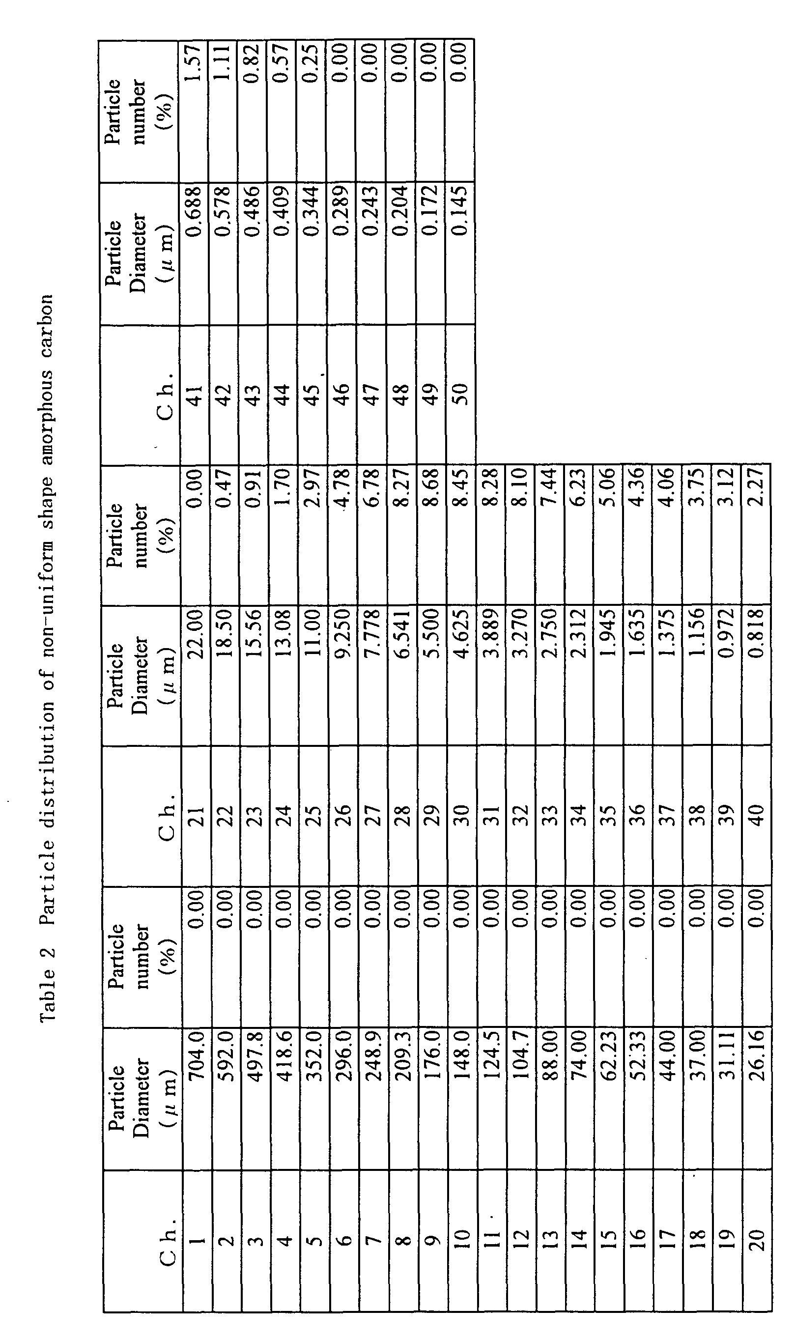
Claims (13)
- The resin bonded abrasive tool characterized in that super abrasive particles and amorphous carbon are distributed in a resin binder phase.
- The resin bonded abrasive tool according to claim 1 characterized in that the amorphous carbon has spherical shape and/or non-uniform shape.
- The resin bonded abrasive tool according to claim 2 characterized in that the non-uniform shape amorphous carbon is prepared by crushing the spherical shape amorphous carbon.
- The resin bonded abrasive tool according to claims 2 or 3 characterized in that the particle diameter of the non-uniform shape amorphous carbon is 20 µm or less.
- The resin bonded abrasive tool according to any of the claims 1 to 4 characterized in that any kind of metal of Cu, Ag, Ni, Co, or the alloy of such metals is coated on the surface of the amorphous carbon.
- The resin bonded abrasive tool according to any of the claims 1 to 5 characterized in that the amorphous carbon is contained in an amount of 5 - 60 vol% with respect to the total volume of the amorphous carbon and the resin binder phase (except super abrasive particles).
- The resin bonded abrasive tool according to any of the claims 1 to 6 characterized in that the hardness of the amorphous carbon Hs = 100 - 120 in shore hardness scale.
- The resin bonded abrasive tool according to any of the claims 1 to 7 characterized in that, additionally, a wear resistant filler is distributed in the resin binder phase.
- The resin bonded abrasive tool according to claim 8 characterized in that the wear resistant filler is selected from SiC, SiO2, Ag, Cu, Ni.
- The resin bonded abrasive tool according to any of the claims 1 to 7 characterized in that, additionally, a lubricative filler is distributed in the resin binder phase.
- The resin bonded abrasive tool according to claim 10 characterized in that the lubricative filler is selected from graphite, hBN, fluoro-resin.
- The resin bonded abrasive tool according to any of the claims 1 to 11 characterized in that pores of 5 - 40 vol% with respect to the total volume of the pores and the resin binder phase (except super abrasive particles).
- The resin bonded abrasive tool according to any of the claims 1 to 11 characterized in that, additionally, a hollow glass is distributed in the resin binder phase.
Applications Claiming Priority (2)
| Application Number | Priority Date | Filing Date | Title |
|---|---|---|---|
| JP2000038653 | 2000-02-16 | ||
| JP2000038653A JP2001138244A (en) | 1999-08-17 | 2000-02-16 | Resin bond whetstone |
Publications (2)
| Publication Number | Publication Date |
|---|---|
| EP1126003A1 true EP1126003A1 (en) | 2001-08-22 |
| EP1126003B1 EP1126003B1 (en) | 2004-04-28 |
Family
ID=18562352
Family Applications (1)
| Application Number | Title | Priority Date | Filing Date |
|---|---|---|---|
| EP01103513A Expired - Lifetime EP1126003B1 (en) | 2000-02-16 | 2001-02-15 | Resin bonded abrasive tool |
Country Status (3)
| Country | Link |
|---|---|
| EP (1) | EP1126003B1 (en) |
| AT (1) | ATE265509T1 (en) |
| DE (1) | DE60102951T2 (en) |
Cited By (4)
| Publication number | Priority date | Publication date | Assignee | Title |
|---|---|---|---|---|
| KR100615896B1 (en) * | 1999-08-17 | 2006-08-28 | 미츠비시 마테리알 가부시키가이샤 | Resin bonded abresive tool |
| WO2011080328A3 (en) * | 2009-12-30 | 2011-09-01 | Sgl Carbon Se | Grinding wheel |
| CN112476257A (en) * | 2019-09-12 | 2021-03-12 | 株式会社迪思科 | Cutting tool, method for manufacturing cutting tool, and method for cutting wafer |
| EP3991915A4 (en) * | 2019-06-27 | 2023-07-19 | Tokyo Diamond Tools Mfg. Co., Ltd. | SYNTHETIC GRINDING STONE |
Families Citing this family (1)
| Publication number | Priority date | Publication date | Assignee | Title |
|---|---|---|---|---|
| DE102019117796A1 (en) | 2019-07-02 | 2021-01-07 | WIKUS-Sägenfabrik Wilhelm H. Kullmann GmbH & Co. KG | Cutting tool with buffer particles |
Citations (5)
| Publication number | Priority date | Publication date | Assignee | Title |
|---|---|---|---|---|
| JPH01188272A (en) * | 1988-01-22 | 1989-07-27 | Semiconductor Energy Lab Co Ltd | Abrasive tool coated with carbon film and manufacture therefor |
| US5095665A (en) * | 1988-06-16 | 1992-03-17 | Noritake Co., Limited | Vitrified super abrasive grain grinding tool |
| JPH04250981A (en) * | 1990-12-27 | 1992-09-07 | Toyoda Mach Works Ltd | Super abrasive grain grinding wheel |
| JPH05277956A (en) * | 1992-03-30 | 1993-10-26 | Mitsubishi Materials Corp | Resin bond grinding wheel |
| JPH10330732A (en) * | 1997-06-04 | 1998-12-15 | Hitachi Chem Co Ltd | Friction material composition and friction material made therefrom |
-
2001
- 2001-02-15 EP EP01103513A patent/EP1126003B1/en not_active Expired - Lifetime
- 2001-02-15 DE DE60102951T patent/DE60102951T2/en not_active Expired - Fee Related
- 2001-02-15 AT AT01103513T patent/ATE265509T1/en not_active IP Right Cessation
Patent Citations (5)
| Publication number | Priority date | Publication date | Assignee | Title |
|---|---|---|---|---|
| JPH01188272A (en) * | 1988-01-22 | 1989-07-27 | Semiconductor Energy Lab Co Ltd | Abrasive tool coated with carbon film and manufacture therefor |
| US5095665A (en) * | 1988-06-16 | 1992-03-17 | Noritake Co., Limited | Vitrified super abrasive grain grinding tool |
| JPH04250981A (en) * | 1990-12-27 | 1992-09-07 | Toyoda Mach Works Ltd | Super abrasive grain grinding wheel |
| JPH05277956A (en) * | 1992-03-30 | 1993-10-26 | Mitsubishi Materials Corp | Resin bond grinding wheel |
| JPH10330732A (en) * | 1997-06-04 | 1998-12-15 | Hitachi Chem Co Ltd | Friction material composition and friction material made therefrom |
Non-Patent Citations (4)
| Title |
|---|
| DATABASE WPI Section Ch Week 199347, Derwent World Patents Index; Class A88, AN 1993-374032, XP002167885 * |
| PATENT ABSTRACTS OF JAPAN vol. 013, no. 477 (M - 885) 27 October 1989 (1989-10-27) * |
| PATENT ABSTRACTS OF JAPAN vol. 017, no. 026 (M - 1354) 19 January 1993 (1993-01-19) * |
| PATENT ABSTRACTS OF JAPAN vol. 1999, no. 03 31 March 1999 (1999-03-31) * |
Cited By (5)
| Publication number | Priority date | Publication date | Assignee | Title |
|---|---|---|---|---|
| KR100615896B1 (en) * | 1999-08-17 | 2006-08-28 | 미츠비시 마테리알 가부시키가이샤 | Resin bonded abresive tool |
| WO2011080328A3 (en) * | 2009-12-30 | 2011-09-01 | Sgl Carbon Se | Grinding wheel |
| EP3991915A4 (en) * | 2019-06-27 | 2023-07-19 | Tokyo Diamond Tools Mfg. Co., Ltd. | SYNTHETIC GRINDING STONE |
| CN112476257A (en) * | 2019-09-12 | 2021-03-12 | 株式会社迪思科 | Cutting tool, method for manufacturing cutting tool, and method for cutting wafer |
| TWI902708B (en) * | 2019-09-12 | 2025-11-01 | 日商迪思科股份有限公司 | Manufacturing method of cutting blade |
Also Published As
| Publication number | Publication date |
|---|---|
| EP1126003B1 (en) | 2004-04-28 |
| DE60102951T2 (en) | 2005-03-31 |
| ATE265509T1 (en) | 2004-05-15 |
| DE60102951D1 (en) | 2004-06-03 |
Similar Documents
| Publication | Publication Date | Title |
|---|---|---|
| US6383238B1 (en) | Resin bonded abrasive tool | |
| US8882868B2 (en) | Abrasive slicing tool for electronics industry | |
| US4671021A (en) | Grinding tool | |
| JP4443870B2 (en) | Super abrasive wheel and manufacturing method thereof | |
| JP2002001668A (en) | Metal bond whetstone | |
| JP4419299B2 (en) | Hybrid grinding wheel and manufacturing method thereof | |
| EP1126003B1 (en) | Resin bonded abrasive tool | |
| KR101861890B1 (en) | A grinding tool for machining brittle materials and a method of making a grinding tool | |
| JP2762661B2 (en) | Porous metal bond whetstone and method of manufacturing the same | |
| JPS6359827B2 (en) | ||
| JP4586704B2 (en) | Resin bond grinding wheel | |
| JPH0790468B2 (en) | Cutter for cutting castings | |
| JP2000288943A (en) | Grindstone containing fibrous hollow graphite | |
| JP2010076094A (en) | Metal bond diamond grinding wheel and method of manufacturing the same | |
| JP4592207B2 (en) | Super abrasive wheel and manufacturing method thereof | |
| JP2022136788A (en) | Metal bond grindstone and method for manufacturing same | |
| JP4318678B2 (en) | Grinding wheel | |
| CN113474123B (en) | Metal bonded grindstone with glass filler | |
| JP4215525B2 (en) | Super Abrasive Metal Bond Wheel | |
| KR101158303B1 (en) | Diamond Tools for Grinding Brittle Materials Having High Hardness | |
| JP2744856B2 (en) | Titanium boride composite silicon carbide sintered body for mechanical seal and mechanical seal | |
| JP5230474B2 (en) | Metal bond wheel | |
| JP2000233374A (en) | METAL BOND DIAMOND GRINDING WHEEL AND ITS MANUFACTURING METHOD | |
| JP2002113665A (en) | Resin bond whetstone | |
| JPH11300623A (en) | Resin bond whetstone |
Legal Events
| Date | Code | Title | Description |
|---|---|---|---|
| PUAI | Public reference made under article 153(3) epc to a published international application that has entered the european phase |
Free format text: ORIGINAL CODE: 0009012 |
|
| AK | Designated contracting states |
Kind code of ref document: A1 Designated state(s): AT BE CH CY DE DK ES FI FR GB GR IE IT LI LU MC NL PT SE TR |
|
| AX | Request for extension of the european patent |
Free format text: AL;LT;LV;MK;RO;SI |
|
| 17P | Request for examination filed |
Effective date: 20010918 |
|
| AKX | Designation fees paid |
Free format text: AT BE CH CY DE DK ES FI FR GB GR IE IT LI LU MC NL PT SE TR |
|
| 17Q | First examination report despatched |
Effective date: 20021002 |
|
| GRAP | Despatch of communication of intention to grant a patent |
Free format text: ORIGINAL CODE: EPIDOSNIGR1 |
|
| GRAS | Grant fee paid |
Free format text: ORIGINAL CODE: EPIDOSNIGR3 |
|
| GRAA | (expected) grant |
Free format text: ORIGINAL CODE: 0009210 |
|
| AK | Designated contracting states |
Kind code of ref document: B1 Designated state(s): AT BE CH CY DE DK ES FI FR GB GR IE IT LI LU MC NL PT SE TR |
|
| PG25 | Lapsed in a contracting state [announced via postgrant information from national office to epo] |
Ref country code: CH Free format text: LAPSE BECAUSE OF FAILURE TO SUBMIT A TRANSLATION OF THE DESCRIPTION OR TO PAY THE FEE WITHIN THE PRESCRIBED TIME-LIMIT Effective date: 20040428 Ref country code: AT Free format text: LAPSE BECAUSE OF FAILURE TO SUBMIT A TRANSLATION OF THE DESCRIPTION OR TO PAY THE FEE WITHIN THE PRESCRIBED TIME-LIMIT Effective date: 20040428 Ref country code: FI Free format text: LAPSE BECAUSE OF FAILURE TO SUBMIT A TRANSLATION OF THE DESCRIPTION OR TO PAY THE FEE WITHIN THE PRESCRIBED TIME-LIMIT Effective date: 20040428 Ref country code: LI Free format text: LAPSE BECAUSE OF FAILURE TO SUBMIT A TRANSLATION OF THE DESCRIPTION OR TO PAY THE FEE WITHIN THE PRESCRIBED TIME-LIMIT Effective date: 20040428 Ref country code: BE Free format text: LAPSE BECAUSE OF FAILURE TO SUBMIT A TRANSLATION OF THE DESCRIPTION OR TO PAY THE FEE WITHIN THE PRESCRIBED TIME-LIMIT Effective date: 20040428 Ref country code: TR Free format text: LAPSE BECAUSE OF FAILURE TO SUBMIT A TRANSLATION OF THE DESCRIPTION OR TO PAY THE FEE WITHIN THE PRESCRIBED TIME-LIMIT Effective date: 20040428 Ref country code: NL Free format text: LAPSE BECAUSE OF FAILURE TO SUBMIT A TRANSLATION OF THE DESCRIPTION OR TO PAY THE FEE WITHIN THE PRESCRIBED TIME-LIMIT Effective date: 20040428 |
|
| REG | Reference to a national code |
Ref country code: GB Ref legal event code: FG4D |
|
| REG | Reference to a national code |
Ref country code: CH Ref legal event code: EP |
|
| REG | Reference to a national code |
Ref country code: IE Ref legal event code: FG4D |
|
| REF | Corresponds to: |
Ref document number: 60102951 Country of ref document: DE Date of ref document: 20040603 Kind code of ref document: P |
|
| PG25 | Lapsed in a contracting state [announced via postgrant information from national office to epo] |
Ref country code: DK Free format text: LAPSE BECAUSE OF FAILURE TO SUBMIT A TRANSLATION OF THE DESCRIPTION OR TO PAY THE FEE WITHIN THE PRESCRIBED TIME-LIMIT Effective date: 20040728 Ref country code: SE Free format text: LAPSE BECAUSE OF FAILURE TO SUBMIT A TRANSLATION OF THE DESCRIPTION OR TO PAY THE FEE WITHIN THE PRESCRIBED TIME-LIMIT Effective date: 20040728 Ref country code: GR Free format text: LAPSE BECAUSE OF FAILURE TO SUBMIT A TRANSLATION OF THE DESCRIPTION OR TO PAY THE FEE WITHIN THE PRESCRIBED TIME-LIMIT Effective date: 20040728 |
|
| PG25 | Lapsed in a contracting state [announced via postgrant information from national office to epo] |
Ref country code: ES Free format text: LAPSE BECAUSE OF FAILURE TO SUBMIT A TRANSLATION OF THE DESCRIPTION OR TO PAY THE FEE WITHIN THE PRESCRIBED TIME-LIMIT Effective date: 20040808 |
|
| NLV1 | Nl: lapsed or annulled due to failure to fulfill the requirements of art. 29p and 29m of the patents act | ||
| REG | Reference to a national code |
Ref country code: CH Ref legal event code: PL |
|
| ET | Fr: translation filed | ||
| PG25 | Lapsed in a contracting state [announced via postgrant information from national office to epo] |
Ref country code: IE Free format text: LAPSE BECAUSE OF NON-PAYMENT OF DUE FEES Effective date: 20050215 Ref country code: LU Free format text: LAPSE BECAUSE OF NON-PAYMENT OF DUE FEES Effective date: 20050215 Ref country code: CY Free format text: LAPSE BECAUSE OF FAILURE TO SUBMIT A TRANSLATION OF THE DESCRIPTION OR TO PAY THE FEE WITHIN THE PRESCRIBED TIME-LIMIT Effective date: 20050215 |
|
| PG25 | Lapsed in a contracting state [announced via postgrant information from national office to epo] |
Ref country code: MC Free format text: LAPSE BECAUSE OF NON-PAYMENT OF DUE FEES Effective date: 20050228 |
|
| PLBE | No opposition filed within time limit |
Free format text: ORIGINAL CODE: 0009261 |
|
| STAA | Information on the status of an ep patent application or granted ep patent |
Free format text: STATUS: NO OPPOSITION FILED WITHIN TIME LIMIT |
|
| 26N | No opposition filed |
Effective date: 20050131 |
|
| REG | Reference to a national code |
Ref country code: IE Ref legal event code: MM4A |
|
| PG25 | Lapsed in a contracting state [announced via postgrant information from national office to epo] |
Ref country code: PT Free format text: LAPSE BECAUSE OF NON-PAYMENT OF DUE FEES Effective date: 20040928 |
|
| PGFP | Annual fee paid to national office [announced via postgrant information from national office to epo] |
Ref country code: DE Payment date: 20090219 Year of fee payment: 9 |
|
| PGFP | Annual fee paid to national office [announced via postgrant information from national office to epo] |
Ref country code: GB Payment date: 20090219 Year of fee payment: 9 |
|
| PGFP | Annual fee paid to national office [announced via postgrant information from national office to epo] |
Ref country code: IT Payment date: 20090223 Year of fee payment: 9 |
|
| PGFP | Annual fee paid to national office [announced via postgrant information from national office to epo] |
Ref country code: FR Payment date: 20090213 Year of fee payment: 9 |
|
| GBPC | Gb: european patent ceased through non-payment of renewal fee |
Effective date: 20100215 |
|
| REG | Reference to a national code |
Ref country code: FR Ref legal event code: ST Effective date: 20101029 |
|
| PG25 | Lapsed in a contracting state [announced via postgrant information from national office to epo] |
Ref country code: FR Free format text: LAPSE BECAUSE OF NON-PAYMENT OF DUE FEES Effective date: 20100301 |
|
| PG25 | Lapsed in a contracting state [announced via postgrant information from national office to epo] |
Ref country code: DE Free format text: LAPSE BECAUSE OF NON-PAYMENT OF DUE FEES Effective date: 20100901 |
|
| PG25 | Lapsed in a contracting state [announced via postgrant information from national office to epo] |
Ref country code: GB Free format text: LAPSE BECAUSE OF NON-PAYMENT OF DUE FEES Effective date: 20100215 Ref country code: IT Free format text: LAPSE BECAUSE OF NON-PAYMENT OF DUE FEES Effective date: 20100215 |