EP1125856A2 - Fluid dispenser - Google Patents
Fluid dispenser Download PDFInfo
- Publication number
- EP1125856A2 EP1125856A2 EP01300910A EP01300910A EP1125856A2 EP 1125856 A2 EP1125856 A2 EP 1125856A2 EP 01300910 A EP01300910 A EP 01300910A EP 01300910 A EP01300910 A EP 01300910A EP 1125856 A2 EP1125856 A2 EP 1125856A2
- Authority
- EP
- European Patent Office
- Prior art keywords
- container
- support plate
- fluid dispenser
- head
- dispenser according
- Prior art date
- Legal status (The legal status is an assumption and is not a legal conclusion. Google has not performed a legal analysis and makes no representation as to the accuracy of the status listed.)
- Granted
Links
Images

Classifications
-
- B—PERFORMING OPERATIONS; TRANSPORTING
- B05—SPRAYING OR ATOMISING IN GENERAL; APPLYING FLUENT MATERIALS TO SURFACES, IN GENERAL
- B05B—SPRAYING APPARATUS; ATOMISING APPARATUS; NOZZLES
- B05B11/00—Single-unit hand-held apparatus in which flow of contents is produced by the muscular force of the operator at the moment of use
- B05B11/01—Single-unit hand-held apparatus in which flow of contents is produced by the muscular force of the operator at the moment of use characterised by the means producing the flow
- B05B11/10—Pump arrangements for transferring the contents from the container to a pump chamber by a sucking effect and forcing the contents out through the dispensing nozzle
- B05B11/1042—Components or details
- B05B11/1059—Means for locking a pump or its actuation means in a fixed position
-
- B—PERFORMING OPERATIONS; TRANSPORTING
- B05—SPRAYING OR ATOMISING IN GENERAL; APPLYING FLUENT MATERIALS TO SURFACES, IN GENERAL
- B05B—SPRAYING APPARATUS; ATOMISING APPARATUS; NOZZLES
- B05B11/00—Single-unit hand-held apparatus in which flow of contents is produced by the muscular force of the operator at the moment of use
- B05B11/01—Single-unit hand-held apparatus in which flow of contents is produced by the muscular force of the operator at the moment of use characterised by the means producing the flow
- B05B11/10—Pump arrangements for transferring the contents from the container to a pump chamber by a sucking effect and forcing the contents out through the dispensing nozzle
- B05B11/1001—Piston pumps
-
- B—PERFORMING OPERATIONS; TRANSPORTING
- B05—SPRAYING OR ATOMISING IN GENERAL; APPLYING FLUENT MATERIALS TO SURFACES, IN GENERAL
- B05B—SPRAYING APPARATUS; ATOMISING APPARATUS; NOZZLES
- B05B11/00—Single-unit hand-held apparatus in which flow of contents is produced by the muscular force of the operator at the moment of use
- B05B11/01—Single-unit hand-held apparatus in which flow of contents is produced by the muscular force of the operator at the moment of use characterised by the means producing the flow
- B05B11/10—Pump arrangements for transferring the contents from the container to a pump chamber by a sucking effect and forcing the contents out through the dispensing nozzle
- B05B11/1042—Components or details
- B05B11/1052—Actuation means
Definitions
- the invention relates to fluid dispensers, and particularly though not exclusively to dispensers for liquid soaps and similar products.
- Liquid soaps and products of a similar type are sold to consumers in a variety of different types of container.
- the soap or other product is typically contained in a container having a pump actuator head that is depressed to dispense the product onto the hand of the consumer.
- the containers can be a wide variety of shapes, and there are different actuator heads and pumping means available, but the dispensers all operate on similar principles, with the actuator head being depressed, the product being drawn up a feed pipe and dispensed through a nozzle in the actuator head onto the user's hand.
- the dispensers are generally simple and convenient to use, but can cause problems when a consumer tries to operate the actuator head and dispense the contents with.only one hand, with the other hand being possibly unavailable to provide support to the dispenser, possibly because of stickiness, greasiness or other problems, or simply where the user simply desires to use only one hand for dispensing the composition.
- many of the designs of dispenser container are not sufficiently stable, especially when they have been emptied to a significant extent, to enable a consumer to operate the actuator head without using the other hand to support the dispenser to prevent it tipping or moving during operation of the actuator head.
- An advantage of the invention is to allow more effective one-handed operation of a fluid dispenser, in particular a pump actuated fluid dispenser.
- the invention provides a manually actuated fluid dispenser comprising:
- the user generally operate fluid dispensers with the thumb or one or more fingers on one hand on the pump actuator head, whilst usually having to catch the dispensed fluid with the other hand, and optionally holding the fluid dispenser steady with the fingers of one or both hands.
- the user may conveniently position one or more fingers or at least part of the palm of the hand to catch dispensed fluid and co-operate with operation of the pump actuator by the thumb of the same hand. In doing this, the dispenser is steadied by virtue of being effectively gripped by the compressive action of the thumb on the pump actuator, and the fingers and/or palm of the same hand on the support plate.
- the thumb may co-operate with operation by one or more fingers, the dispensed fluid being caught on part of the thumb or hand, with the dispenser being generally steadied in a similar manner.
- part of the hand or one or more of the fingers is employed under the support plate to hold the dispenser steady as the pump is actuated to dispense the product onto the same hand that the user is using to operate the pump.
- the support plate may be advantageously formed from injection moulded plastics material.
- the support plate comprises a separate collar portion which can be located adjacent or actually on the neck portion of the container, which has depending therefrom a projecting support plate portion.
- the collar portion and the projecting plate portion are integrally formed together.
- the support plate may be integrally moulded with the container and located on or closely adjacent the neck portion of the container bottle, using for example conventional blow moulding techniques which are used to manufacture the container bottle itself.
- the support plate may conveniently be located within about 5 cm, more conveniently within about 3 cm of the bottom of the neck, i.e. where the neck of the container joins the container bottle.
- the neck of the container will be a distinct and readily identifiable part of the container, often at or near the top of the container when it is stood in its normal manner on a horizontal surface. Often it takes the form of a substantially tubular opening through which the contents of the container may be dosed into and dispensed from the container. However in the absence of such a readily identifiable (e.g. tubular) portion, the neck of the container can be regarded as the opening through which the contents of the container are dosed and dispensed.
- the projecting plate portion is sufficiently rigid so that it does not bend under the co-operating action of the fingers and thumb of the user.
- the support plate is provided as part of a separate collar, preferably the collar is mounted on the neck portion of the container so that it does not move relative to the container bottle when the user operates the actuator head.
- the support plate depends from only a portion of the periphery of the neck, though embodiments are envisaged where the support plate may entirely surround the periphery of the neck.
- the support plate may take any of a variety of configurations, and may for example have minimal (e.g. 3 mm or so) width. It need not necessarily be generally planar (though it may be in preferred embodiments), as embodiments are envisaged where it may comprise for example a gently curved, generally smooth, downwardly pointing hook or lip. It is however important that it fulfils its functional requirements, which is to facilitate a compressive action between the part of the hand actuating the dispenser and the part of the hand onto which the dispensed substance is dispensed, whilst simultaneously allowing the dispenser to be steadied.
- the pump actuator head comprises an internal mounting recess for mounting the head on the neck portion, the recess having a region towards its lower edge having a diameter greater than the external diameter of the collar portion of the support plate such that the pump actuator head moves down over the collar when the head is depressed to dispense the product in the container bottle.
- the alternative embodiment is specifically envisaged, in which on dispensing the pump actuator head moves within the collar on depression of the actuator head.
- the support plate is mounted on the container in a position which is in general alignment with the pump actuator head when it is in the operable position.
- Many commercially available dispenser pumps operate in such a manner that the pump means, which in use is located inside the dispensing container (or the container neck), has its relative position releasably secured during assembly and manufacture of the commercial product.
- it is necessary to release and reconfigure the pump actuator relative to the pump means. This may typically be done by depressing or raising the pump actuator from a first position relative to the secured pump means, and twisting the pump actuator by e.g. one quarter or one half of a turn to a second position. In the first position the pump cannot be depressed or actuated, whilst in the second it can.
- an added advantage of the invention may lie in that the positioning of the support plate, which may provide an indication to the user of whether the actuator head is in an open position or a closed position.
- the dispenser head and the support plate may be in general alignment, whereas when the dispenser is in the inoperable or closed position, they are not.
- This can be used to simplify opening of the container, as the user does not have to consult instructions or consider which way to rotate the dispenser head to prime the container for use, but simply to rotate it to generally align with the support plate.
- the support plate may take the form of a plurality (e.g. two, or possibly more) projecting plate portions on generally opposing sides of the collar. This is particularly advantageous if the user needs to apply a greater amount of force than usual to the actuator head, or if the container is small such that the user can hold it in one hand and dispense the product at the same time.
- the container contents may be dispensed by engaging the first two fingers of a given hand underneath the projecting support plate.portions on either side of the collar, and the thumb may then be used to depress the actuator head and dispense the contents.
- a dispenser 1 comprises a container bottle 2 having a neck portion 3 and a body portion 4.
- a liquid product 5 such as liquid soap is contained within the container body 4.
- a pump 6 extends into the container body portion 4, is operated by the depression of a pump actuator head 7, and has depending therefrom a diptube which extends to the bottom of body portion 4, through which liquid product 5 to be dispensed may pass. Pump 6 is secured relative to neck portion 3 by any convenient means.
- a support plate 8 Mounted on the neck portion 3 of the container 2, below the head 7 is a support plate 8 comprising a collar portion 9 and a projecting plate portion 10.
- the projecting plate portion 10 is rigid, and the support plate 8 is securely mounted via the collar portion 9 on the neck portion 3 of the container 2 so that is does not move relative to the container bottle 2 when the actuator head 7 is depressed, even if it is grasped e.g. in the manner described herein in depressing head 7 and dispensing the liquid product.
- the pump actuator head 7 comprises a depressor face 11 that in use is typically contacted by a user's thumb to depress the head 7 to dispense product 5, a nozzle 12 through which product 5 is dispensed, and a mounting portion 13 having an internal mounting recess 14 for mounting the head 7 on the neck portion 3.
- the recess 14 has a region 15 having a diameter greater than the external diameter of the collar portion 9 of the support plate 8 such that the pump actuator head 7 can move down over the collar 9 when the head 7 is depressed to dispense the product 5 in the container 2, as shown in Figure 5.
- the projecting plate portion 10 of the support plate 8 can be used to provide an indication to a user of whether the actuator head 7 is in an open or operable position, or a closed or inoperable position, and in which direction it is necessary to rotate the head 7 to move it from a closed to an open position.
- Figure 1 shows the head 7 in a closed position. To move the head 7 to an open position such that the product 5 can be dispensed, it is unlocked and rotated in the direction of the projecting plate portion 10, as shown in Figures 3, 4 and 5, optionally in conjunction with at least partially raising or depressing the actuator head 7 relative to the container bottle 2. This is easy for a user to determine, without having to examine the top of the head 7 or the back of the container for instructions on which way to rotate the head 7. Such instructions can be difficult to decipher, particularly for those with poor eyesight.
- the body portion 4 of the container also preferably has located adjacent and underneath the projecting plate 10 a depression 16, which depression 16 is conveniently integrally moulded with the container body 4 in general alignment with projecting plate 10.
- Depression 16 may act to accommodate a finger of the user, typically the index finger when the user is dispensing the contents of the container using a thumb to depress the actuator, and may enable the user to obtain better purchase on the underside of the projecting plate 10 during dispensing.
- the dispenser of the invention can readily be operated with one hand by a user, with the support plate enabling the user to use the thumb and finger or fingers of one hand to operate the pump and stabilise the dispenser while dispensing the product onto the same hand.
Landscapes
- Closures For Containers (AREA)
- Containers And Packaging Bodies Having A Special Means To Remove Contents (AREA)
- Transition And Organic Metals Composition Catalysts For Addition Polymerization (AREA)
- Nozzles (AREA)
- Details Of Rigid Or Semi-Rigid Containers (AREA)
Abstract
Description
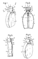
- Figure 1 shows a perspective view of a dispenser according to the invention with the actuator head in a closed position;
- Figure 2 shows a cross-sectional view of the dispenser of Figure 1 along the line A-A;
- Figure 3 shows a side view of the dispenser of Figure 1;
- Figure 4 shows a perspective view of the dispenser according to the invention with the actuator head in an open position; and
- Figure 5 shows a perspective view of the dispenser of Figure 4 with the head depressed to dispense a product.
Claims (11)
- A manually actuated fluid dispenser comprising:a container bottle having a neck portion;a pump;a pump actuator head mounted on the container neck portion; anda support plate located on the container neck portion below the pump actuator head.
- A fluid dispenser according to claim 1 wherein the support plate is formed from injection moulded plastics material.
- A fluid dispenser according to claim 1 or claim 2 wherein the support plate comprises a collar portion for mounting on the neck portion of the container and a projecting plate portion.
- A fluid dispenser according to claim 3 wherein the collar portion and the projecting plate portion are integrally formed together.
- A fluid dispenser according to any of the preceding claims wherein the support plate is rigid.
- A fluid dispenser according to any one of the preceding claims wherein the collar of the support plate is mounted on the neck portion of the container so that it does not move relative to the container bottle when the user operates the actuator head.
- A fluid dispenser according to any one of the preceding claims wherein the pump actuator head comprises an internal mounting recess for mounting the head on the neck portion, the recess having a region towards its lower edge having a diameter greater than the external diameter of the collar portion of the support plate such that the pump actuator head moves down over the collar when the head is depressed to dispense the product in the container.
- A fluid dispenser according to any one of the preceding claims wherein the support plate is mounted on the container with the projecting plate in a position corresponding to the open position of the pump actuator head.
- A fluid dispenser according to any one of the preceding claims wherein the support plate has a second projecting plate portion on the opposite side of the collar to the first projecting plate portion.
- A fluid dispenser according to any of the preceding claims, wherein the container bottle has located therein adjacent the neck portion a depression.
- A fluid dispenser as herein before described with reference to the accompanying drawings.
Applications Claiming Priority (2)
| Application Number | Priority Date | Filing Date | Title |
|---|---|---|---|
| GBGB0002751.6A GB0002751D0 (en) | 2000-02-07 | 2000-02-07 | Fluid dispenser |
| GB0002751 | 2000-02-07 |
Publications (3)
| Publication Number | Publication Date |
|---|---|
| EP1125856A2 true EP1125856A2 (en) | 2001-08-22 |
| EP1125856A3 EP1125856A3 (en) | 2003-12-10 |
| EP1125856B1 EP1125856B1 (en) | 2009-10-28 |
Family
ID=9885088
Family Applications (1)
| Application Number | Title | Priority Date | Filing Date |
|---|---|---|---|
| EP01300910A Expired - Lifetime EP1125856B1 (en) | 2000-02-07 | 2001-02-01 | Fluid dispenser |
Country Status (7)
| Country | Link |
|---|---|
| US (1) | US6533144B2 (en) |
| EP (1) | EP1125856B1 (en) |
| AT (1) | ATE446920T1 (en) |
| CA (1) | CA2334077C (en) |
| DE (1) | DE60140281D1 (en) |
| ES (1) | ES2334881T3 (en) |
| GB (1) | GB0002751D0 (en) |
Cited By (2)
| Publication number | Priority date | Publication date | Assignee | Title |
|---|---|---|---|---|
| JP2015145251A (en) * | 2014-01-31 | 2015-08-13 | 株式会社吉野工業所 | Pump type extractor |
| JP2015145250A (en) * | 2014-01-31 | 2015-08-13 | 株式会社吉野工業所 | Pump type extractor |
Families Citing this family (23)
| Publication number | Priority date | Publication date | Assignee | Title |
|---|---|---|---|---|
| US7191920B2 (en) * | 2002-09-25 | 2007-03-20 | Conopco, Inc. | Motorized household liquid dispenser |
| US7762427B2 (en) * | 2005-06-10 | 2010-07-27 | Kranson Industries, Inc. | Pump dispensing mechanism |
| USD538665S1 (en) | 2006-02-14 | 2007-03-20 | Conopco, Inc. | Bottle |
| NL2000206C2 (en) * | 2006-08-31 | 2008-03-03 | Robert Veeger | Dispensing device for dispensing a liquid substance. |
| US7735688B2 (en) * | 2006-10-10 | 2010-06-15 | Meadwestvaco Calmar, Inc. | Rotating collar and locking and venting closure connector for an air foaming pump dispenser |
| WO2009075687A1 (en) * | 2007-12-13 | 2009-06-18 | Colgate-Palmolive Company | A fragrance dispensing pump head |
| US8167220B2 (en) * | 2009-09-21 | 2012-05-01 | Berlin Packaging, Llc | Headpiece for actuator |
| CA139564S (en) | 2010-09-15 | 2011-10-18 | Unilever Plc | Container cover |
| CA139562S (en) * | 2010-09-15 | 2011-10-20 | Unilever Plc | Bottle with pump |
| CA139563S (en) | 2010-09-15 | 2011-10-20 | Unilever Plc | Bottle with pump |
| CA139561S (en) * | 2010-09-15 | 2011-10-20 | Unilever Plc | Bottle with pump |
| CA139565S (en) | 2010-09-15 | 2011-10-18 | Unilever Plc | Container with pump |
| US8814007B2 (en) | 2010-12-31 | 2014-08-26 | Medline Industries, Inc. | Dispenser with directional flow controlling flange and corresponding systems |
| JP6165648B2 (en) * | 2014-01-31 | 2017-07-19 | 株式会社吉野工業所 | Pump type dispenser |
| US9730502B2 (en) | 2014-07-24 | 2017-08-15 | Eman Naura | Substance applicator |
| WO2017010955A1 (en) | 2015-07-15 | 2017-01-19 | Şahsan Maki̇na Kalip Elektrik Ve Elektronik Sanayi̇ Ve Ti̇caret Li̇mi̇ted Şi̇rketi̇ | Claw skip mechanism with level adjustment |
| USD826720S1 (en) | 2016-12-22 | 2018-08-28 | Conopco, Inc. | Bottle |
| USD824779S1 (en) * | 2016-12-22 | 2018-08-07 | 800 Sylvan Avenue | Package |
| USD830840S1 (en) | 2016-12-22 | 2018-10-16 | Conopco, Inc. | Container |
| JP6901369B2 (en) * | 2017-09-29 | 2021-07-14 | 株式会社吉野工業所 | Container with pump |
| WO2020072750A1 (en) * | 2018-10-04 | 2020-04-09 | Flocon, Inc. | Container appendage |
| DE102021003171A1 (en) | 2020-06-25 | 2021-12-30 | Thomas Götz | Dispenser head for a disinfectant dispenser, disinfectant dispenser, disinfectant container and method for dispensing disinfectant |
| USD1114628S1 (en) * | 2024-05-03 | 2026-02-24 | Method Products, Pbc | Dispenser |
Family Cites Families (11)
| Publication number | Priority date | Publication date | Assignee | Title |
|---|---|---|---|---|
| GB648490A (en) | 1947-07-18 | 1951-01-03 | British Thomson Houston Co Ltd | Improvements in and relating to dynamo electric machines |
| US2837247A (en) * | 1956-09-24 | 1958-06-03 | Drackett Co | Dispensing pump units |
| US4124148A (en) | 1975-12-24 | 1978-11-07 | Firma Carl Vieler | Apparatus for a container with an atomizer for, in particular, cosmetic fluids |
| US4434917A (en) | 1981-05-26 | 1984-03-06 | Yoshino Kogyosho Co., Ltd. | Trigger-actuated atomizer |
| JPS58122065A (en) * | 1982-01-13 | 1983-07-20 | Canyon Corp | Dispenser |
| US4615476A (en) * | 1982-07-26 | 1986-10-07 | Huntington Laboratories, Inc. | Fluid-dispensing apparatus |
| KR920000591A (en) | 1990-06-15 | 1992-01-29 | 데쓰야 다다 | Combination of vessels and manual push dispensers with push buttons |
| FR2690422B1 (en) * | 1992-04-22 | 1995-03-31 | Sofab | Dispenser for fluid products. |
| US5405057A (en) * | 1993-10-21 | 1995-04-11 | Moore; David G. | Manually actuated pump |
| JPH08100762A (en) * | 1994-10-03 | 1996-04-16 | Hironori Handa | Hand pump which can be used by one hand |
| FR2740431B1 (en) * | 1995-10-30 | 1997-12-12 | Sofab | PERMEABLE WALL LIQUID DISPENSING BOTTLE |
-
2000
- 2000-02-07 GB GBGB0002751.6A patent/GB0002751D0/en not_active Ceased
-
2001
- 2001-02-01 DE DE60140281T patent/DE60140281D1/en not_active Expired - Lifetime
- 2001-02-01 ES ES01300910T patent/ES2334881T3/en not_active Expired - Lifetime
- 2001-02-01 EP EP01300910A patent/EP1125856B1/en not_active Expired - Lifetime
- 2001-02-01 AT AT01300910T patent/ATE446920T1/en not_active IP Right Cessation
- 2001-02-02 CA CA002334077A patent/CA2334077C/en not_active Expired - Fee Related
- 2001-02-07 US US09/778,167 patent/US6533144B2/en not_active Expired - Fee Related
Cited By (2)
| Publication number | Priority date | Publication date | Assignee | Title |
|---|---|---|---|---|
| JP2015145251A (en) * | 2014-01-31 | 2015-08-13 | 株式会社吉野工業所 | Pump type extractor |
| JP2015145250A (en) * | 2014-01-31 | 2015-08-13 | 株式会社吉野工業所 | Pump type extractor |
Also Published As
| Publication number | Publication date |
|---|---|
| DE60140281D1 (en) | 2009-12-10 |
| GB0002751D0 (en) | 2000-03-29 |
| US6533144B2 (en) | 2003-03-18 |
| ES2334881T3 (en) | 2010-03-17 |
| EP1125856B1 (en) | 2009-10-28 |
| CA2334077A1 (en) | 2001-08-07 |
| ATE446920T1 (en) | 2009-11-15 |
| CA2334077C (en) | 2008-08-19 |
| EP1125856A3 (en) | 2003-12-10 |
| US20010052528A1 (en) | 2001-12-20 |
Similar Documents
| Publication | Publication Date | Title |
|---|---|---|
| EP1125856B1 (en) | Fluid dispenser | |
| JP5576871B2 (en) | Portable aerosol dispenser | |
| US4765515A (en) | Liquid dispensing combination | |
| AU777805B2 (en) | Ergonomic trigger sprayer having side saddle supports | |
| US7137536B2 (en) | Inverted aerosol dispenser | |
| JP4201985B2 (en) | Liquid spray device | |
| US8640926B2 (en) | Dispenser with flexible cover | |
| US20010032864A1 (en) | Fluid container for pump or spray device | |
| EP2451724B1 (en) | Spray through cap for a pressurised fluid container | |
| US20050098584A1 (en) | Dispensing device with pivoting spray nozzle | |
| EP0759007A1 (en) | Container cover and dispensing device | |
| US7261268B2 (en) | Wall mountable holder for a container | |
| US7762427B2 (en) | Pump dispensing mechanism | |
| US7093741B2 (en) | Applicator and integrated concentrate system | |
| JP2566859Y2 (en) | Dispensing container | |
| WO1998022008A1 (en) | Dosing dispenser for liquid soap or the like | |
| JP3937279B2 (en) | Liquid container | |
| GB2342407A (en) | Dispensing pump usable with one hand | |
| JP7619904B2 (en) | Pump with saucer and pump container with saucer | |
| JP2008508990A (en) | Dispensers, especially metering dispensers | |
| JP7830175B2 (en) | Liquid dispensing actuator and dispensing vessel | |
| JP2020050372A (en) | Measuring cup and combination of measuring cup and push cock | |
| JPH09249248A (en) | Fixed amount discharge container | |
| JP7770370B2 (en) | Push Bottles and Push Kits | |
| JP7849194B2 (en) | Liquid discharge actuators, liquid discharge containers, and liquid discharge products |
Legal Events
| Date | Code | Title | Description |
|---|---|---|---|
| PUAI | Public reference made under article 153(3) epc to a published international application that has entered the european phase |
Free format text: ORIGINAL CODE: 0009012 |
|
| AK | Designated contracting states |
Kind code of ref document: A2 Designated state(s): AT BE CH CY DE DK ES FI FR GB GR IE IT LI LU MC NL PT SE TR |
|
| AX | Request for extension of the european patent |
Free format text: AL;LT;LV;MK;RO;SI |
|
| PUAL | Search report despatched |
Free format text: ORIGINAL CODE: 0009013 |
|
| AK | Designated contracting states |
Kind code of ref document: A3 Designated state(s): AT BE CH CY DE DK ES FI FR GB GR IE IT LI LU MC NL PT SE TR |
|
| AX | Request for extension of the european patent |
Extension state: AL LT LV MK RO SI |
|
| 17P | Request for examination filed |
Effective date: 20040301 |
|
| RAP1 | Party data changed (applicant data changed or rights of an application transferred) |
Owner name: UNILEVER N.V. Owner name: UNILEVER PLC |
|
| RAP1 | Party data changed (applicant data changed or rights of an application transferred) |
Owner name: UNILEVER N.V. Owner name: UNILEVER PLC |
|
| AKX | Designation fees paid |
Designated state(s): AT BE CH CY DE DK ES FI FR GB GR IE IT LI LU MC NL PT SE TR |
|
| 17Q | First examination report despatched |
Effective date: 20080221 |
|
| RAP1 | Party data changed (applicant data changed or rights of an application transferred) |
Owner name: UNILEVER N.V. Owner name: UNILEVER PLC |
|
| GRAP | Despatch of communication of intention to grant a patent |
Free format text: ORIGINAL CODE: EPIDOSNIGR1 |
|
| GRAS | Grant fee paid |
Free format text: ORIGINAL CODE: EPIDOSNIGR3 |
|
| GRAA | (expected) grant |
Free format text: ORIGINAL CODE: 0009210 |
|
| RIN1 | Information on inventor provided before grant (corrected) |
Inventor name: SCHUEDDEKOPF, HOLGER Inventor name: DAVIES, JONATHAN NEIL |
|
| AK | Designated contracting states |
Kind code of ref document: B1 Designated state(s): AT BE CH CY DE DK ES FI FR GB GR IE IT LI LU MC NL PT SE TR |
|
| REG | Reference to a national code |
Ref country code: GB Ref legal event code: FG4D |
|
| REG | Reference to a national code |
Ref country code: CH Ref legal event code: EP |
|
| REG | Reference to a national code |
Ref country code: IE Ref legal event code: FG4D |
|
| REF | Corresponds to: |
Ref document number: 60140281 Country of ref document: DE Date of ref document: 20091210 Kind code of ref document: P |
|
| REG | Reference to a national code |
Ref country code: ES Ref legal event code: FG2A Ref document number: 2334881 Country of ref document: ES Kind code of ref document: T3 |
|
| NLV1 | Nl: lapsed or annulled due to failure to fulfill the requirements of art. 29p and 29m of the patents act | ||
| PG25 | Lapsed in a contracting state [announced via postgrant information from national office to epo] |
Ref country code: SE Free format text: LAPSE BECAUSE OF FAILURE TO SUBMIT A TRANSLATION OF THE DESCRIPTION OR TO PAY THE FEE WITHIN THE PRESCRIBED TIME-LIMIT Effective date: 20091028 Ref country code: FI Free format text: LAPSE BECAUSE OF FAILURE TO SUBMIT A TRANSLATION OF THE DESCRIPTION OR TO PAY THE FEE WITHIN THE PRESCRIBED TIME-LIMIT Effective date: 20091028 Ref country code: PT Free format text: LAPSE BECAUSE OF FAILURE TO SUBMIT A TRANSLATION OF THE DESCRIPTION OR TO PAY THE FEE WITHIN THE PRESCRIBED TIME-LIMIT Effective date: 20100301 |
|
| PG25 | Lapsed in a contracting state [announced via postgrant information from national office to epo] |
Ref country code: CY Free format text: LAPSE BECAUSE OF FAILURE TO SUBMIT A TRANSLATION OF THE DESCRIPTION OR TO PAY THE FEE WITHIN THE PRESCRIBED TIME-LIMIT Effective date: 20091028 |
|
| PG25 | Lapsed in a contracting state [announced via postgrant information from national office to epo] |
Ref country code: BE Free format text: LAPSE BECAUSE OF FAILURE TO SUBMIT A TRANSLATION OF THE DESCRIPTION OR TO PAY THE FEE WITHIN THE PRESCRIBED TIME-LIMIT Effective date: 20091028 Ref country code: AT Free format text: LAPSE BECAUSE OF FAILURE TO SUBMIT A TRANSLATION OF THE DESCRIPTION OR TO PAY THE FEE WITHIN THE PRESCRIBED TIME-LIMIT Effective date: 20091028 |
|
| PG25 | Lapsed in a contracting state [announced via postgrant information from national office to epo] |
Ref country code: DK Free format text: LAPSE BECAUSE OF FAILURE TO SUBMIT A TRANSLATION OF THE DESCRIPTION OR TO PAY THE FEE WITHIN THE PRESCRIBED TIME-LIMIT Effective date: 20091028 |
|
| PLBE | No opposition filed within time limit |
Free format text: ORIGINAL CODE: 0009261 |
|
| STAA | Information on the status of an ep patent application or granted ep patent |
Free format text: STATUS: NO OPPOSITION FILED WITHIN TIME LIMIT |
|
| REG | Reference to a national code |
Ref country code: CH Ref legal event code: PL |
|
| 26N | No opposition filed |
Effective date: 20100729 |
|
| PG25 | Lapsed in a contracting state [announced via postgrant information from national office to epo] |
Ref country code: LI Free format text: LAPSE BECAUSE OF NON-PAYMENT OF DUE FEES Effective date: 20100228 Ref country code: MC Free format text: LAPSE BECAUSE OF NON-PAYMENT OF DUE FEES Effective date: 20100301 Ref country code: GR Free format text: LAPSE BECAUSE OF FAILURE TO SUBMIT A TRANSLATION OF THE DESCRIPTION OR TO PAY THE FEE WITHIN THE PRESCRIBED TIME-LIMIT Effective date: 20100129 Ref country code: CH Free format text: LAPSE BECAUSE OF NON-PAYMENT OF DUE FEES Effective date: 20100228 |
|
| PG25 | Lapsed in a contracting state [announced via postgrant information from national office to epo] |
Ref country code: IE Free format text: LAPSE BECAUSE OF NON-PAYMENT OF DUE FEES Effective date: 20100201 |
|
| PG25 | Lapsed in a contracting state [announced via postgrant information from national office to epo] |
Ref country code: LU Free format text: LAPSE BECAUSE OF NON-PAYMENT OF DUE FEES Effective date: 20100201 Ref country code: NL Free format text: LAPSE BECAUSE OF FAILURE TO SUBMIT A TRANSLATION OF THE DESCRIPTION OR TO PAY THE FEE WITHIN THE PRESCRIBED TIME-LIMIT Effective date: 20091028 |
|
| PG25 | Lapsed in a contracting state [announced via postgrant information from national office to epo] |
Ref country code: TR Free format text: LAPSE BECAUSE OF FAILURE TO SUBMIT A TRANSLATION OF THE DESCRIPTION OR TO PAY THE FEE WITHIN THE PRESCRIBED TIME-LIMIT Effective date: 20091028 |
|
| PGFP | Annual fee paid to national office [announced via postgrant information from national office to epo] |
Ref country code: DE Payment date: 20140227 Year of fee payment: 14 |
|
| PGFP | Annual fee paid to national office [announced via postgrant information from national office to epo] |
Ref country code: FR Payment date: 20140220 Year of fee payment: 14 Ref country code: ES Payment date: 20140226 Year of fee payment: 14 Ref country code: IT Payment date: 20140226 Year of fee payment: 14 |
|
| PGFP | Annual fee paid to national office [announced via postgrant information from national office to epo] |
Ref country code: GB Payment date: 20140227 Year of fee payment: 14 |
|
| REG | Reference to a national code |
Ref country code: DE Ref legal event code: R119 Ref document number: 60140281 Country of ref document: DE |
|
| GBPC | Gb: european patent ceased through non-payment of renewal fee |
Effective date: 20150201 |
|
| REG | Reference to a national code |
Ref country code: FR Ref legal event code: ST Effective date: 20151030 |
|
| PG25 | Lapsed in a contracting state [announced via postgrant information from national office to epo] |
Ref country code: IT Free format text: LAPSE BECAUSE OF NON-PAYMENT OF DUE FEES Effective date: 20150201 |
|
| PG25 | Lapsed in a contracting state [announced via postgrant information from national office to epo] |
Ref country code: DE Free format text: LAPSE BECAUSE OF NON-PAYMENT OF DUE FEES Effective date: 20150901 Ref country code: GB Free format text: LAPSE BECAUSE OF NON-PAYMENT OF DUE FEES Effective date: 20150201 |
|
| PG25 | Lapsed in a contracting state [announced via postgrant information from national office to epo] |
Ref country code: FR Free format text: LAPSE BECAUSE OF NON-PAYMENT OF DUE FEES Effective date: 20150302 |
|
| REG | Reference to a national code |
Ref country code: ES Ref legal event code: FD2A Effective date: 20160329 |
|
| PG25 | Lapsed in a contracting state [announced via postgrant information from national office to epo] |
Ref country code: ES Free format text: LAPSE BECAUSE OF NON-PAYMENT OF DUE FEES Effective date: 20150202 |