EP1125786A2 - Engine speed control for assisting shift synchronisation - Google Patents
Engine speed control for assisting shift synchronisation Download PDFInfo
- Publication number
- EP1125786A2 EP1125786A2 EP01103397A EP01103397A EP1125786A2 EP 1125786 A2 EP1125786 A2 EP 1125786A2 EP 01103397 A EP01103397 A EP 01103397A EP 01103397 A EP01103397 A EP 01103397A EP 1125786 A2 EP1125786 A2 EP 1125786A2
- Authority
- EP
- European Patent Office
- Prior art keywords
- engine
- torque
- speed
- engine speed
- value
- Prior art date
- Legal status (The legal status is an assumption and is not a legal conclusion. Google has not performed a legal analysis and makes no representation as to the accuracy of the status listed.)
- Granted
Links
- 238000000034 method Methods 0.000 claims abstract description 14
- 230000005540 biological transmission Effects 0.000 claims description 13
- 230000007423 decrease Effects 0.000 description 10
- 230000001360 synchronised effect Effects 0.000 description 5
- 230000009347 mechanical transmission Effects 0.000 description 4
- 230000007246 mechanism Effects 0.000 description 2
- 238000013459 approach Methods 0.000 description 1
- 238000002485 combustion reaction Methods 0.000 description 1
- 230000001419 dependent effect Effects 0.000 description 1
- 238000006073 displacement reaction Methods 0.000 description 1
- 239000000446 fuel Substances 0.000 description 1
- 230000006872 improvement Effects 0.000 description 1
- 230000008569 process Effects 0.000 description 1
- 230000004044 response Effects 0.000 description 1
- 238000004904 shortening Methods 0.000 description 1
Images

Classifications
-
- B—PERFORMING OPERATIONS; TRANSPORTING
- B60—VEHICLES IN GENERAL
- B60W—CONJOINT CONTROL OF VEHICLE SUB-UNITS OF DIFFERENT TYPE OR DIFFERENT FUNCTION; CONTROL SYSTEMS SPECIALLY ADAPTED FOR HYBRID VEHICLES; ROAD VEHICLE DRIVE CONTROL SYSTEMS FOR PURPOSES NOT RELATED TO THE CONTROL OF A PARTICULAR SUB-UNIT
- B60W10/00—Conjoint control of vehicle sub-units of different type or different function
- B60W10/04—Conjoint control of vehicle sub-units of different type or different function including control of propulsion units
- B60W10/06—Conjoint control of vehicle sub-units of different type or different function including control of propulsion units including control of combustion engines
-
- B—PERFORMING OPERATIONS; TRANSPORTING
- B60—VEHICLES IN GENERAL
- B60W—CONJOINT CONTROL OF VEHICLE SUB-UNITS OF DIFFERENT TYPE OR DIFFERENT FUNCTION; CONTROL SYSTEMS SPECIALLY ADAPTED FOR HYBRID VEHICLES; ROAD VEHICLE DRIVE CONTROL SYSTEMS FOR PURPOSES NOT RELATED TO THE CONTROL OF A PARTICULAR SUB-UNIT
- B60W10/00—Conjoint control of vehicle sub-units of different type or different function
- B60W10/10—Conjoint control of vehicle sub-units of different type or different function including control of change-speed gearings
- B60W10/11—Stepped gearings
-
- B—PERFORMING OPERATIONS; TRANSPORTING
- B60—VEHICLES IN GENERAL
- B60W—CONJOINT CONTROL OF VEHICLE SUB-UNITS OF DIFFERENT TYPE OR DIFFERENT FUNCTION; CONTROL SYSTEMS SPECIALLY ADAPTED FOR HYBRID VEHICLES; ROAD VEHICLE DRIVE CONTROL SYSTEMS FOR PURPOSES NOT RELATED TO THE CONTROL OF A PARTICULAR SUB-UNIT
- B60W30/00—Purposes of road vehicle drive control systems not related to the control of a particular sub-unit, e.g. of systems using conjoint control of vehicle sub-units
- B60W30/18—Propelling the vehicle
-
- F—MECHANICAL ENGINEERING; LIGHTING; HEATING; WEAPONS; BLASTING
- F02—COMBUSTION ENGINES; HOT-GAS OR COMBUSTION-PRODUCT ENGINE PLANTS
- F02D—CONTROLLING COMBUSTION ENGINES
- F02D31/00—Use of speed-sensing governors to control combustion engines, not otherwise provided for
- F02D31/001—Electric control of rotation speed
- F02D31/007—Electric control of rotation speed controlling fuel supply
-
- B—PERFORMING OPERATIONS; TRANSPORTING
- B60—VEHICLES IN GENERAL
- B60W—CONJOINT CONTROL OF VEHICLE SUB-UNITS OF DIFFERENT TYPE OR DIFFERENT FUNCTION; CONTROL SYSTEMS SPECIALLY ADAPTED FOR HYBRID VEHICLES; ROAD VEHICLE DRIVE CONTROL SYSTEMS FOR PURPOSES NOT RELATED TO THE CONTROL OF A PARTICULAR SUB-UNIT
- B60W2710/00—Output or target parameters relating to a particular sub-units
- B60W2710/06—Combustion engines, Gas turbines
- B60W2710/0644—Engine speed
-
- B—PERFORMING OPERATIONS; TRANSPORTING
- B60—VEHICLES IN GENERAL
- B60W—CONJOINT CONTROL OF VEHICLE SUB-UNITS OF DIFFERENT TYPE OR DIFFERENT FUNCTION; CONTROL SYSTEMS SPECIALLY ADAPTED FOR HYBRID VEHICLES; ROAD VEHICLE DRIVE CONTROL SYSTEMS FOR PURPOSES NOT RELATED TO THE CONTROL OF A PARTICULAR SUB-UNIT
- B60W2710/00—Output or target parameters relating to a particular sub-units
- B60W2710/06—Combustion engines, Gas turbines
- B60W2710/0666—Engine torque
-
- F—MECHANICAL ENGINEERING; LIGHTING; HEATING; WEAPONS; BLASTING
- F02—COMBUSTION ENGINES; HOT-GAS OR COMBUSTION-PRODUCT ENGINE PLANTS
- F02D—CONTROLLING COMBUSTION ENGINES
- F02D2250/00—Engine control related to specific problems or objectives
- F02D2250/18—Control of the engine output torque
Definitions
- the present invention relates to automatic control of engine speed in a fully or partially automated vehicular transmission system including an electronically controlled engine, preferably communicating over an electronic data link and allowing control in at least a speed-limiting mode and in a torque-limiting mode.
- the present invention relates to control of engine speed for such systems when a relatively large decrease in engine speed is required, typically when synchronizing for an upshift.
- the current fully or partially automated transmission systems may include an electronically controlled engine having control logic conforming to and/or communicating over an electronic data link conforming to an industry standard protocol, such as SAE J-1922, SAE J-1939, ISO 11898 or the like.
- SAE J-1922, SAE J-1939, ISO 11898 or the like may be included in the current fully or partially automated transmission systems.
- U.S. Pats. No. 5,457,633 and 5,738,606 are illustrative of such electronically controlled internal combustion (usually diesel) engines.
- Such systems have an engine speed mode of operation wherein the engine is controlled to achieve a target engine speed.
- the engines are programmed to respond to engine speed mode commands by fueling the engine to achieve the target engine speed in a smooth, ramped manner.
- the prior art systems are subject to improvement, as when commanding a relatively large decrease in engine speed in the speed control mode of operation, usually during a single or skip upshift, a longer-than-desirable time may be required to achieve the target engine speed.
- the drawbacks of the prior art are minimized or overcome by shortening the time required to achieve a relatively large decrease in engine speed to a target engine speed.
- the foregoing is accomplished by operating in a torque control mode requesting a low torque, preferably zero torque, not in a speed control mode, when a significant decrease in engine speed is required.
- a torque control mode requesting a low torque, preferably zero torque, not in a speed control mode
- engine speed will decrease in an unmodulated manner according to the "decay rate" of the engine.
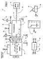
- Fig. 1 is a schematic illustration of a vehicular automated mechanical transmission system of the type with which the improved engine speed control of the present invention is particularly advantageously utilized.
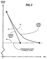
- Fig. 2 is a graphical representation of the rate of decrease in engine speed in a speed control mode versus a torque control mode of a typical heavy-duty diesel engine operating under an industry standard data link protocol such as SAE J-1922 or SAE J-1939.
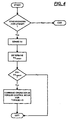
- Fig. 3 is a schematic illustration, in flow chart format, of the engine speed control of the present invention.
- Fig. 4 is a schematic illustration, in flow chart format, of an alternate embodiment of the present invention.
- the powertrain 10 includes a well-known diesel engine 12 and a multiple-speed, change-gear mechanical transmission 14 drivingly connected to the engine by means of a master friction clutch 16 and having an output shaft 18 connected to a final drive (such as a drive axle) 20, by means of a prop shaft 22 and universal joints.
- the crankshaft 24 of the engine drives the input elements 26 of the master clutch 16, which are frictionally engageable to and disengageable from output elements 28 carried by the transmission input shaft 30.
- a manual 32 or automatic 34 control controls the engagement and disengagement of the master friction clutch 16.
- Transmission 14 is preferably a 9-to-18-forward-speed transmission controlled by a manual shift lever 36 or an automatically controlled X-Y shifter 38 acting on a shift bar housing or shift shaft mechanism.
- Transmission 14 is preferably a compound-type transmission of the range, splitter or combined range-and-splitter type, as may be seen in greater detail by reference to U.S. Pats. No. 4,754,665 and 5,390,561, the disclosures of which are incorporated herein by reference.
- transmission 14 is of the mechanical type in which speed ratios are engaged and disengaged by means of engaging and disengaging one or more jaw clutches, which are preferably but not necessarily of the non-synchronized type.
- a throttle pedal monitor assembly 40 monitors the position or displacement of the throttle pedal 42 and provides a signal (THL) indicative thereof.
- the engine includes a controller, preferably a microprocessor-based controller 44, which communicates over an electronic data link and is effective to fuel the engine in accordance with commands over the data link. Typically, commands will request fueling to match operator throttle settings or to achieve a required engine speed and/or provide a maximum output (i.e., flywheel) torque.
- a microprocessor-based system controller 46 receives input signals 48 from the throttle pedal position sensor 40, the transmission shift actuator 38, signal GR T , from the driver command console 50, signal ES indicative of engine speed from sensor 52, signal IS from input shaft speed sensor 54, and/or signal OS from output shaft speed sensor 56.
- the input signals also may include a signal from the clutch actuator 34 indicative of the engaged or disengaged condition of master clutch 16 and/or the transmission operator 38.
- X-Y shift mechanisms and shift position sensors may be seen by reference to U.S. Pats. No. 5,729,110 and 5,743,143.
- the system controller will process these input signals in accordance with predetermined logic rules to issue command output signals 58 to various system actuators, including the engine controller 44.
- ECU 46 may be integral with the engine controller 44.
- Torque usually is requested as a percentage of the maximum rated gross, output or other torque rating of the engine.
- Applicants have discovered that when a significant decrease in engine speed is required, by using the torque control mode or the speed- and torque-limiting mode and requesting that maximum torque to set to a relatively low value (such as zero torque), the engine will decelerate toward the desired engine speed as quickly as possible without any attempt by the engine controller to smoothly ramp the value. This will assure that the maximum engine deceleration rate is obtained and shorten the time to complete an upshift.
- Line 64 in Fig. 2 schematically illustrates engine speed in the torque control mode with a zero torque command. A similar line would be seen in the speed- and torque-limiting mode of operation. As the speeds of the engaging jaw clutch members pass through synchronous, the jaw clutch members will engage.
- FIG. 3 is a schematic illustration, in flow chart format, of the upshift engine speed control method of the present invention. This is less desirable, as the system may cause engine speed to "chase" torsional vibrations in the driveline.
- the engine then may be commanded to operate in the engine speed control mode and to achieve the exact target engine speed.
Landscapes
- Engineering & Computer Science (AREA)
- Chemical & Material Sciences (AREA)
- Combustion & Propulsion (AREA)
- Mechanical Engineering (AREA)
- Transportation (AREA)
- General Engineering & Computer Science (AREA)
- Automation & Control Theory (AREA)
- Control Of Vehicle Engines Or Engines For Specific Uses (AREA)
- Control Of Transmission Device (AREA)
- Electrical Control Of Air Or Fuel Supplied To Internal-Combustion Engine (AREA)
- Combined Controls Of Internal Combustion Engines (AREA)
Abstract
Description
- The present invention relates to automatic control of engine speed in a fully or partially automated vehicular transmission system including an electronically controlled engine, preferably communicating over an electronic data link and allowing control in at least a speed-limiting mode and in a torque-limiting mode. In particular, the present invention relates to control of engine speed for such systems when a relatively large decrease in engine speed is required, typically when synchronizing for an upshift.
- Fully and partially automated mechanical transmission systems intended for medium- and heavy-duty vehicular use are well known in the prior art, as may be seen by reference to U.S. Pats. No. 4,361,060; 4,595,986; 4,648,290; 4,850,236; 5,582,558; 5,735,771; 5,755,639; 5,797,110; 5,894,758 and 5,904,635, the disclosures of which are incorporated herein by reference. Such systems typically involve some automatic control of engine speed to synchronize for engaging a target gear ratio.
- The current fully or partially automated transmission systems may include an electronically controlled engine having control logic conforming to and/or communicating over an electronic data link conforming to an industry standard protocol, such as SAE J-1922, SAE J-1939, ISO 11898 or the like. U.S. Pats. No. 5,457,633 and 5,738,606 are illustrative of such electronically controlled internal combustion (usually diesel) engines.
- Such systems have an engine speed mode of operation wherein the engine is controlled to achieve a target engine speed. In heavy-duty diesel engines, the engines are programmed to respond to engine speed mode commands by fueling the engine to achieve the target engine speed in a smooth, ramped manner.
- The prior art systems are subject to improvement, as when commanding a relatively large decrease in engine speed in the speed control mode of operation, usually during a single or skip upshift, a longer-than-desirable time may be required to achieve the target engine speed.
- In accordance with the present invention, the drawbacks of the prior art are minimized or overcome by shortening the time required to achieve a relatively large decrease in engine speed to a target engine speed.
- The foregoing is accomplished by operating in a torque control mode requesting a low torque, preferably zero torque, not in a speed control mode, when a significant decrease in engine speed is required. For the electronically controlled heavy-and medium-duty diesel engines produced by engine manufacturers, when in the torque control mode and when defueling to reduce torque, engine speed will decrease in an unmodulated manner according to the "decay rate" of the engine.
- Accordingly, it is an object of the present invention to provide an improved engine speed control when substantial decreases in engine speed are required, such as in upshifts, which will decrease the time required to reach the desired engine speed.
- This and other objects and advantages of the present invention will become apparent from a reading of the following description of the preferred embodiment taken in connection with the attached drawings.
- Fig. 1 is a schematic illustration of a vehicular automated mechanical transmission system of the type with which the improved engine speed control of the present invention is particularly advantageously utilized.
- Fig. 2 is a graphical representation of the rate of decrease in engine speed in a speed control mode versus a torque control mode of a typical heavy-duty diesel engine operating under an industry standard data link protocol such as SAE J-1922 or SAE J-1939.
- Fig. 3 is a schematic illustration, in flow chart format, of the engine speed control of the present invention.
- Fig. 4 is a schematic illustration, in flow chart format, of an alternate embodiment of the present invention.
- A typical
vehicular powertrain 10 for a land vehicle, such as a heavy-duty or medium-duty truck, is schematically illustrated in Fig. 1. Thepowertrain 10 includes a well-knowndiesel engine 12 and a multiple-speed, change-gearmechanical transmission 14 drivingly connected to the engine by means of amaster friction clutch 16 and having anoutput shaft 18 connected to a final drive (such as a drive axle) 20, by means of aprop shaft 22 and universal joints. Thecrankshaft 24 of the engine drives theinput elements 26 of themaster clutch 16, which are frictionally engageable to and disengageable fromoutput elements 28 carried by thetransmission input shaft 30. A manual 32 or automatic 34 control controls the engagement and disengagement of themaster friction clutch 16.Transmission 14 is preferably a 9-to-18-forward-speed transmission controlled by amanual shift lever 36 or an automatically controlledX-Y shifter 38 acting on a shift bar housing or shift shaft mechanism. -
Transmission 14 is preferably a compound-type transmission of the range, splitter or combined range-and-splitter type, as may be seen in greater detail by reference to U.S. Pats. No. 4,754,665 and 5,390,561, the disclosures of which are incorporated herein by reference. Preferably,transmission 14 is of the mechanical type in which speed ratios are engaged and disengaged by means of engaging and disengaging one or more jaw clutches, which are preferably but not necessarily of the non-synchronized type. - A throttle
pedal monitor assembly 40 monitors the position or displacement of thethrottle pedal 42 and provides a signal (THL) indicative thereof. The engine includes a controller, preferably a microprocessor-basedcontroller 44, which communicates over an electronic data link and is effective to fuel the engine in accordance with commands over the data link. Typically, commands will request fueling to match operator throttle settings or to achieve a required engine speed and/or provide a maximum output (i.e., flywheel) torque. - A microprocessor-based
system controller 46 receivesinput signals 48 from the throttlepedal position sensor 40, thetransmission shift actuator 38, signal GRT, from thedriver command console 50, signal ES indicative of engine speed fromsensor 52, signal IS from inputshaft speed sensor 54, and/or signal OS from outputshaft speed sensor 56. The input signals also may include a signal from theclutch actuator 34 indicative of the engaged or disengaged condition ofmaster clutch 16 and/or thetransmission operator 38. X-Y shift mechanisms and shift position sensors may be seen by reference to U.S. Pats. No. 5,729,110 and 5,743,143. The system controller will process these input signals in accordance with predetermined logic rules to issuecommand output signals 58 to various system actuators, including theengine controller 44. In certain systems, ECU 46 may be integral with theengine controller 44. - As is well known, electronically controlled, heavy-duty diesel engines conforming to industry standard protocols such as SAE J-1922 and/or SAE J-1939 will receive and obey commands to operate in at least four different modes:
- (1) a mode wherein engine fueling is under control of the vehicle
operator and the engine will be fueled in accordance with the operator's
positioning of the
throttle pedal 42; - (2) an engine speed control mode wherein the engine will be fueled to achieve a commanded engine speed;
- (3) a torque control mode wherein the engine will be fueled such that engine torque will achieve a requested maximum engine torque; and
- (4) a speed- and torque-limiting mode wherein the engine is fueled such that engine speed and engine torque will not exceed requested maximum values thereof.
-
- Torque usually is requested as a percentage of the maximum rated gross, output or other torque rating of the engine.
- To complete a desired single or skip upshift by engaging non-synchronized jaw clutches, it is required that the engine speed be lowered to a substantially synchronous value (ESTARGET = (OX x GRT) ± X). See, for example, U.S. Pat. No. 5,682,790, the disclosure of which is incorporated herein by reference.
- In the prior art automated mechanical transmission systems, when it was necessary to significantly reduce engine speed to synchronize for engaging an upshift target gear ratio, the engine was commanded to operate in the engine speed control mode to achieve the target engine speed (ES = ESTARGET). The engine then would implement the governor control required to reach this desired speed. The engine deceleration rate that occurs is dependent upon the engine manufacturer's implementation of the speed control mode and can sometimes be undesirably slow, as the implementation attempts to smoothly ramp to the target engine speed. "Ramped" is used to mean a modulated rate of deceleration less than the rate of unmodulated engine deceleration.
Line 62 in Fig. 2 schematically illustrates a typical response in the engine speed control mode to decrease engine speed to the desired engine speed to engage the target gear ratio. - According to the present invention, Applicants have discovered that when a significant decrease in engine speed is required, by using the torque control mode or the speed- and torque-limiting mode and requesting that maximum torque to set to a relatively low value (such as zero torque), the engine will decelerate toward the desired engine speed as quickly as possible without any attempt by the engine controller to smoothly ramp the value. This will assure that the maximum engine deceleration rate is obtained and shorten the time to complete an upshift.
Line 64 in Fig. 2 schematically illustrates engine speed in the torque control mode with a zero torque command. A similar line would be seen in the speed- and torque-limiting mode of operation. As the speeds of the engaging jaw clutch members pass through synchronous, the jaw clutch members will engage. This is especially true for engaging splitter clutches, which do require precision to engage. Fig. 3 is a schematic illustration, in flow chart format, of the upshift engine speed control method of the present invention. This is less desirable, as the system may cause engine speed to "chase" torsional vibrations in the driveline. - In another alternative mode, illustrated in Fig. 4, whenever current engine speed exceeds target engine speed (ES > ESTARGET), operation in the torque control mode or the speed- and torque-limiting mode may be commanded.
- Alternatively, as engine speed approaches within a relatively narrow band (about ± 10-20 RPM) of the target
synchronous speed 66, the engine then may be commanded to operate in the engine speed control mode and to achieve the exact target engine speed. - Although the present invention has been described with a certain degree of particularity, it is understood that the description of the preferred embodiment is by way of example only and that numerous changes to form and detail are possible without departing from the spirit and scope of the invention as hereinafter claimed.
Claims (14)
- A method for controlling engine speed in an automated transmission system including an electronically controlled engine having (i) a speed control mode of operation wherein the engine is fueled to cause engine speed to equal a desired engine speed value (ESTARGET) in a ramped manner and (ii) at least one of (a) a torque control mode of operation wherein the engine is fueled to cause engine torque to be a requested engine torque value and engine deceleration is not modulated, and (b) a speed- and torque-limiting mode wherein the engine is fueled to cause engine torque to be no greater than a requested engine torque value and engine deceleration is not modulated, said method characterized by the steps of:sensing current engine speed (ES);determining a desired engine speed (ESTARGET); andif the difference between current and desired engine speed exceeds a first reference value ((ES ESTARGET) > REF1), commanding operation in one of said torque control mode of operation to cause torque to equal a minimal engine torque value and said speed- and torque-limiting mode of operation to limit torque to a minimal engine torque value.
- The method of claim 1 including the further step of:
if a change in engine speed is required and the difference between current and desired engine speed is less than said first reference value ((ES-ESTARGET) < REF1), commanding operation in said speed control mode of operation to cause engine speed to equal a required engine speed. - The method of claim 1 wherein said minimal torque value is about zero torque.
- The method of claim 1 wherein said engine includes a microprocessor-based engine controller communicating over an electronic data link.
- The method of claim 4 wherein said data link conforms to an industry standard protocol corresponding to one of SAE J-1922, SAE J-1939 and/or ISO 11898.
- The method of claim 1 wherein said reference value is about 10-20 RPM.
- A control system for controlling engine speed in an automated transmission system including an electronically controlled engine, a microprocessor-based engine controller communicating over an electronic data link and including logic rules having (i) a speed control mode of operation wherein the engine is fueled to cause engine speed to equal a desired engine speed value (ESTARGET) in a ramped manner and (ii) at least one of (a) a torque control mode of operation wherein the engine is fueled to cause engine torque to be a requested engine torque value and engine deceleration is not modulated, and (b) a speed- and torque-limiting mode wherein the engine is fueled to cause engine torque to be no greater than a requested engine torque value and engine deceleration is not modulated, said control system characterized by said engine controller including logic rules for:sensing current engine speed (ES);determining a desired engine speed (ESTARGET); andif the difference between current and desired engine speed exceeds a first reference value ((ES ESTARGET) > REF1), commanding operation in one of said torque control mode of operation to cause torque to equal a minimal engine torque value and said speed- and torque-limiting mode of operation to limit torque to a minimal engine torque value.
- The control system of claim 7 wherein said logic rules are effective:
if a change in engine speed is required and the difference between current and desired engine speed is less than said first reference value ((ES-ESTARGET) < REF1), commanding operation in said speed control mode of operation to cause engine speed to equal a required engine speed. - The control system of claim 7 wherein said minimal torque value is about zero torque.
- The control system of claim 7 wherein said data link conforms to an industry standard protocol corresponding to one of SAE J-1922, SAE J-1939 and/or ISO 11898.
- The control system of claim 7 wherein said reference value (REF1) is about 10-20 RPM.
- A method for controlling engine speed in an automated transmission system including an electronically controlled engine having (i) a speed control mode of operation wherein the engine is fueled to cause engine speed to equal a desired engine speed value (ESTARGET) in a ramped manner and (ii) at least one of (a) a torque control mode of operation wherein the engine is fueled to cause engine torque to be a requested engine torque value and engine deceleration is not modulated, and (b) a speed- and torque-limiting mode wherein the engine is fueled to cause engine torque to be no greater than a requested engine torque value and engine deceleration is not modulated, said method characterized by the steps of:sensing current engine speed (ES);determining a desired engine speed (ESTARGET); andif current engine speed exceeds desired engine speed (ES > ESTARGET), commanding operation in one of said torque control mode of operation to cause torque to equal a minimal engine torque value and said speed- and torque-limiting mode of operation to limit torque to a minimal engine torque value.
- The method of claim 12 wherein said minimal torque value is about zero torque.
- The method of claim 13 wherein said engine includes a microprocessor-based engine controller communicating over an electronic data link.
Applications Claiming Priority (2)
| Application Number | Priority Date | Filing Date | Title |
|---|---|---|---|
| US09/504,426 US6220219B1 (en) | 2000-02-15 | 2000-02-15 | Engine speed control for decreasing engine speed |
| US504426 | 2000-02-15 |
Publications (3)
| Publication Number | Publication Date |
|---|---|
| EP1125786A2 true EP1125786A2 (en) | 2001-08-22 |
| EP1125786A3 EP1125786A3 (en) | 2005-04-20 |
| EP1125786B1 EP1125786B1 (en) | 2007-03-21 |
Family
ID=24006209
Family Applications (1)
| Application Number | Title | Priority Date | Filing Date |
|---|---|---|---|
| EP01103397A Expired - Lifetime EP1125786B1 (en) | 2000-02-15 | 2001-02-14 | Engine speed control for assisting shift synchronisation |
Country Status (5)
| Country | Link |
|---|---|
| US (1) | US6220219B1 (en) |
| EP (1) | EP1125786B1 (en) |
| JP (1) | JP2001271684A (en) |
| BR (1) | BR0100743B1 (en) |
| DE (1) | DE60127330T2 (en) |
Families Citing this family (12)
| Publication number | Priority date | Publication date | Assignee | Title |
|---|---|---|---|---|
| DE10392600D2 (en) * | 2002-12-23 | 2005-02-03 | Luk Lamellen & Kupplungsbau | Method and device for incorrect monitoring of an electronic control device of an automatic transmission arranged in the drive train of a motor vehicle |
| US6875155B2 (en) * | 2003-06-02 | 2005-04-05 | Eaton Corporation | Automatic splitter and governor control for manually shifted transmission |
| US6878097B2 (en) * | 2003-06-02 | 2005-04-12 | Eaton Corporation | Automatic splitter and governor control for manually shifted transmission |
| US7160224B2 (en) * | 2004-05-14 | 2007-01-09 | General Motors Corporation | Single motor recovery for an electrically variable transmission |
| JP5041974B2 (en) * | 2006-11-16 | 2012-10-03 | ヤマハ発動機株式会社 | Control system and vehicle |
| EP2367711B1 (en) * | 2008-11-21 | 2019-08-07 | Volvo Construction Equipment AB | Pedal map shift |
| BR112014004809A2 (en) | 2011-08-29 | 2017-03-21 | Crown Equip Corp | system method and vehicle |
| EP4167042A1 (en) * | 2011-08-29 | 2023-04-19 | Crown Equipment Corporation | Multimode vehicular navigation control |
| AU2012302054B2 (en) | 2011-08-29 | 2014-11-13 | Crown Equipment Corporation | Vehicular navigation control interface |
| JP5838829B2 (en) * | 2012-01-24 | 2016-01-06 | トヨタ自動車株式会社 | Internal combustion engine control device |
| DE102013223612A1 (en) * | 2013-11-20 | 2015-05-21 | Zf Friedrichshafen Ag | Method for adapting a calculated engine torque |
| CN104828066B (en) * | 2014-12-04 | 2017-07-11 | 北汽福田汽车股份有限公司 | Vehicle and its reversing protection control method |
Citations (17)
| Publication number | Priority date | Publication date | Assignee | Title |
|---|---|---|---|---|
| US4361060A (en) | 1978-01-24 | 1982-11-30 | Smyth Robert Ralston | Mechanical automatic transmission |
| US4595986A (en) | 1984-10-09 | 1986-06-17 | Eaton Corporation | Method for control of automatic mechanical transmission system utilizing a microprocessor based electronic controller |
| US4648290A (en) | 1984-07-23 | 1987-03-10 | Eaton Corporation | Semi-automatic mechanical transmission control |
| US4754665A (en) | 1986-02-05 | 1988-07-05 | Eaton Corporation | Auxiliary transmission section |
| US4850236A (en) | 1987-11-20 | 1989-07-25 | Eaton Corporation | Vehicle drive line shift control system and method |
| US5390561A (en) | 1993-05-20 | 1995-02-21 | Eaton Corporation | Compound transmission |
| US5457633A (en) | 1994-02-24 | 1995-10-10 | Caterpillar Inc. | Apparatus for limiting horsepower output of an engine and method of operating same |
| US5582558A (en) | 1995-07-27 | 1996-12-10 | Rockwell International Corporation | Combined system for assisting shifting of manual transmission |
| US5682790A (en) | 1996-04-30 | 1997-11-04 | Eaton Corporation | Synchronizing and gear engagement sensing logic for automated mechanical transmission system |
| US5729110A (en) | 1995-10-10 | 1998-03-17 | Eaton Corporation | Method for controlling an electronic X-Y shifting mechanism for a vehicle transmission |
| US5735771A (en) | 1996-04-30 | 1998-04-07 | Eaton Corporation | Semi-automatic shift implementation |
| US5738606A (en) | 1996-09-30 | 1998-04-14 | Cummins Engine Company, Inc. | Control system for regulating output torque of an internal combustion engine |
| US5743143A (en) | 1996-08-09 | 1998-04-28 | Eaton Corporation | Transmission shifting mechanism and position sensor |
| US5755639A (en) | 1996-04-30 | 1998-05-26 | Eaton Corporation | Semi-automatic shift implementation with automatic splitter shifting |
| US5797110A (en) | 1995-11-17 | 1998-08-18 | Eaton Corporation | Engine torque control |
| US5894758A (en) | 1997-12-15 | 1999-04-20 | Eaton Corporation | Assisted lever-shifted transmission |
| US5904635A (en) | 1997-08-07 | 1999-05-18 | Eaton Corporation | Partially automated lever-shifted mechanical transmission system |
Family Cites Families (5)
| Publication number | Priority date | Publication date | Assignee | Title |
|---|---|---|---|---|
| US4714144A (en) * | 1986-04-18 | 1987-12-22 | Eaton Corporation | Method for controlling AMT system start from stop operation |
| JPH0759214A (en) * | 1993-08-11 | 1995-03-03 | Mitsubishi Electric Corp | Shift shock prevention device for vehicles equipped with automatic transmission |
| SE502807C2 (en) * | 1994-05-13 | 1996-01-22 | Scania Cv Ab | Procedure for controlling the engine torque during shifting |
| US5498195A (en) * | 1994-11-10 | 1996-03-12 | Cummins Electronics Company, Inc. | Apparatus and method for verifying gear engagement in controlling the automatic shifting of a manual-automatic transmission |
| US5741202A (en) * | 1996-05-20 | 1998-04-21 | Meritor Heavy Vehicle Systems, Llc | Shift by wire transmission system |
-
2000
- 2000-02-15 US US09/504,426 patent/US6220219B1/en not_active Expired - Lifetime
-
2001
- 2001-02-14 DE DE60127330T patent/DE60127330T2/en not_active Expired - Lifetime
- 2001-02-14 EP EP01103397A patent/EP1125786B1/en not_active Expired - Lifetime
- 2001-02-14 BR BRPI0100743-2B1A patent/BR0100743B1/en not_active IP Right Cessation
- 2001-02-15 JP JP2001038524A patent/JP2001271684A/en active Pending
Patent Citations (17)
| Publication number | Priority date | Publication date | Assignee | Title |
|---|---|---|---|---|
| US4361060A (en) | 1978-01-24 | 1982-11-30 | Smyth Robert Ralston | Mechanical automatic transmission |
| US4648290A (en) | 1984-07-23 | 1987-03-10 | Eaton Corporation | Semi-automatic mechanical transmission control |
| US4595986A (en) | 1984-10-09 | 1986-06-17 | Eaton Corporation | Method for control of automatic mechanical transmission system utilizing a microprocessor based electronic controller |
| US4754665A (en) | 1986-02-05 | 1988-07-05 | Eaton Corporation | Auxiliary transmission section |
| US4850236A (en) | 1987-11-20 | 1989-07-25 | Eaton Corporation | Vehicle drive line shift control system and method |
| US5390561A (en) | 1993-05-20 | 1995-02-21 | Eaton Corporation | Compound transmission |
| US5457633A (en) | 1994-02-24 | 1995-10-10 | Caterpillar Inc. | Apparatus for limiting horsepower output of an engine and method of operating same |
| US5582558A (en) | 1995-07-27 | 1996-12-10 | Rockwell International Corporation | Combined system for assisting shifting of manual transmission |
| US5729110A (en) | 1995-10-10 | 1998-03-17 | Eaton Corporation | Method for controlling an electronic X-Y shifting mechanism for a vehicle transmission |
| US5797110A (en) | 1995-11-17 | 1998-08-18 | Eaton Corporation | Engine torque control |
| US5682790A (en) | 1996-04-30 | 1997-11-04 | Eaton Corporation | Synchronizing and gear engagement sensing logic for automated mechanical transmission system |
| US5755639A (en) | 1996-04-30 | 1998-05-26 | Eaton Corporation | Semi-automatic shift implementation with automatic splitter shifting |
| US5735771A (en) | 1996-04-30 | 1998-04-07 | Eaton Corporation | Semi-automatic shift implementation |
| US5743143A (en) | 1996-08-09 | 1998-04-28 | Eaton Corporation | Transmission shifting mechanism and position sensor |
| US5738606A (en) | 1996-09-30 | 1998-04-14 | Cummins Engine Company, Inc. | Control system for regulating output torque of an internal combustion engine |
| US5904635A (en) | 1997-08-07 | 1999-05-18 | Eaton Corporation | Partially automated lever-shifted mechanical transmission system |
| US5894758A (en) | 1997-12-15 | 1999-04-20 | Eaton Corporation | Assisted lever-shifted transmission |
Also Published As
| Publication number | Publication date |
|---|---|
| DE60127330T2 (en) | 2007-12-20 |
| JP2001271684A (en) | 2001-10-05 |
| BR0100743A (en) | 2002-02-05 |
| EP1125786B1 (en) | 2007-03-21 |
| DE60127330D1 (en) | 2007-05-03 |
| US6220219B1 (en) | 2001-04-24 |
| BR0100743B1 (en) | 2014-04-15 |
| EP1125786A3 (en) | 2005-04-20 |
Similar Documents
| Publication | Publication Date | Title |
|---|---|---|
| EP1059189B1 (en) | Engine output torque control for powertrain with engageable positive clutches | |
| US6042507A (en) | Torque converter lockup control | |
| EP1020663B1 (en) | Automated transmission upshift control | |
| EP0720929B1 (en) | Vehicle engine fuel control during start-up | |
| EP1125786B1 (en) | Engine speed control for assisting shift synchronisation | |
| EP1020664B1 (en) | Automated transmission downshift control | |
| EP1070625B1 (en) | Starting and driveline shock protection control method and system | |
| US7344474B2 (en) | Control for selecting automated transmission system shift strategy | |
| EP1152172B1 (en) | Automated transmission upshift control | |
| EP1070879B1 (en) | Adaptive automated transmission upshift control | |
| EP1069350A1 (en) | Inertia brake control | |
| AU3533900A (en) | Powertrain torque control | |
| US6375596B1 (en) | Control to determine input shaft direction of rotation | |
| CA1304473C (en) | Method for controlling amt system including after transmission gear change fuel control | |
| US6406403B1 (en) | Torque ramp down control | |
| US6461272B1 (en) | Vehicle synchronization algorithm for driveline protection | |
| EP1186808B1 (en) | Shift control method for an automatic transmission | |
| US6283892B1 (en) | Active in-gear positioning | |
| US6178366B1 (en) | Method/system for initiating automatic upshifting in an automated mechanical transmission system | |
| EP0985856B1 (en) | Method/system for controlling upshifting in an automated mechanical transmission system |
Legal Events
| Date | Code | Title | Description |
|---|---|---|---|
| PUAI | Public reference made under article 153(3) epc to a published international application that has entered the european phase |
Free format text: ORIGINAL CODE: 0009012 |
|
| AK | Designated contracting states |
Kind code of ref document: A2 Designated state(s): AT BE CH CY DE DK ES FI FR GB GR IE IT LI LU MC NL PT SE TR |
|
| AX | Request for extension of the european patent |
Free format text: AL;LT;LV;MK;RO;SI |
|
| PUAL | Search report despatched |
Free format text: ORIGINAL CODE: 0009013 |
|
| AK | Designated contracting states |
Kind code of ref document: A3 Designated state(s): AT BE CH CY DE DK ES FI FR GB GR IE IT LI LU MC NL PT SE TR |
|
| AX | Request for extension of the european patent |
Extension state: AL LT LV MK RO SI |
|
| 17P | Request for examination filed |
Effective date: 20050923 |
|
| AKX | Designation fees paid |
Designated state(s): DE FR GB IT |
|
| GRAP | Despatch of communication of intention to grant a patent |
Free format text: ORIGINAL CODE: EPIDOSNIGR1 |
|
| RIC1 | Information provided on ipc code assigned before grant |
Ipc: F16H 61/04 20060101ALN20060406BHEP Ipc: B60W 10/06 20060101ALI20060406BHEP Ipc: B60W 10/10 20060101AFI20060406BHEP |
|
| GRAS | Grant fee paid |
Free format text: ORIGINAL CODE: EPIDOSNIGR3 |
|
| GRAA | (expected) grant |
Free format text: ORIGINAL CODE: 0009210 |
|
| AK | Designated contracting states |
Kind code of ref document: B1 Designated state(s): DE FR GB IT |
|
| REG | Reference to a national code |
Ref country code: GB Ref legal event code: FG4D |
|
| REF | Corresponds to: |
Ref document number: 60127330 Country of ref document: DE Date of ref document: 20070503 Kind code of ref document: P |
|
| ET | Fr: translation filed | ||
| PLBE | No opposition filed within time limit |
Free format text: ORIGINAL CODE: 0009261 |
|
| STAA | Information on the status of an ep patent application or granted ep patent |
Free format text: STATUS: NO OPPOSITION FILED WITHIN TIME LIMIT |
|
| 26N | No opposition filed |
Effective date: 20071227 |
|
| PG25 | Lapsed in a contracting state [announced via postgrant information from national office to epo] |
Ref country code: IT Free format text: LAPSE BECAUSE OF FAILURE TO SUBMIT A TRANSLATION OF THE DESCRIPTION OR TO PAY THE FEE WITHIN THE PRESCRIBED TIME-LIMIT Effective date: 20070321 |
|
| REG | Reference to a national code |
Ref country code: FR Ref legal event code: PLFP Year of fee payment: 16 |
|
| REG | Reference to a national code |
Ref country code: FR Ref legal event code: PLFP Year of fee payment: 17 |
|
| REG | Reference to a national code |
Ref country code: FR Ref legal event code: PLFP Year of fee payment: 18 |
|
| PGFP | Annual fee paid to national office [announced via postgrant information from national office to epo] |
Ref country code: GB Payment date: 20180122 Year of fee payment: 18 Ref country code: DE Payment date: 20180122 Year of fee payment: 18 |
|
| PGFP | Annual fee paid to national office [announced via postgrant information from national office to epo] |
Ref country code: FR Payment date: 20180123 Year of fee payment: 18 |
|
| REG | Reference to a national code |
Ref country code: GB Ref legal event code: 732E Free format text: REGISTERED BETWEEN 20181115 AND 20181130 |
|
| REG | Reference to a national code |
Ref country code: DE Ref legal event code: R119 Ref document number: 60127330 Country of ref document: DE |
|
| GBPC | Gb: european patent ceased through non-payment of renewal fee |
Effective date: 20190214 |
|
| PG25 | Lapsed in a contracting state [announced via postgrant information from national office to epo] |
Ref country code: DE Free format text: LAPSE BECAUSE OF NON-PAYMENT OF DUE FEES Effective date: 20190903 Ref country code: GB Free format text: LAPSE BECAUSE OF NON-PAYMENT OF DUE FEES Effective date: 20190214 |
|
| PG25 | Lapsed in a contracting state [announced via postgrant information from national office to epo] |
Ref country code: FR Free format text: LAPSE BECAUSE OF NON-PAYMENT OF DUE FEES Effective date: 20190228 |