BACKGROUND OF THE INVENTION
Field of the Invention
-
The present invention relates to a liquid
discharge head to discharge a liquid by generating a
bubble by acting a thermal energy to the liquid, a
liquid discharge method using the liquid discharge
head, a recovery method, a liquid discharge apparatus,
and a fluid structure body.
-
The present invention is applicable to an
apparatus such as a printer to carry out recording to a
recording medium such as a paper, thread, fiber,
fabric, leather, metal, plastic, glass, wood, and
ceramic, copier, facsimile having a communication
system, and word processor having a printer part and an
industrial recording apparatus in composite combination
with various processing apparatus.
-
For reference, "recording" in the present
invention means not only attaching an image such as a
character and a figure having a meaning to the
recording medium, but also attaching the image such as
a pattern without any meaning.
Related Background Art
-
Conventionally, in a recording apparatus such as
printer, an ink jet recording method, namely, so-called
bubble jet recording method, in which such energy as
heat is applied to a liquid ink in a flow path to
generate the bubble and the ink is discharged from a
discharge port by an action force caused by an acute
volume change according to generation of the bubble to
form the image by attaching this to the recording
medium, has been known. In the recording apparatus
using the bubble jet recording method, as disclosed in
U. S. Patent No. 4723129, the discharge port to
discharge the ink, the flow path communicating with the
discharge port, and an electrothermal converting
element as energy generating means to discharge the ink
flown in the flow path is generally arranged.
-
According to such recording method, a high quality
image can be recorded in a high speed and with a low
noise and also in the head to do this recording method,
the discharge port to discharge the ink can be arranged
in a high density and thus, there are many advantageous
points in which a small apparatus can easily yield the
recorded image of a high resolution and a color image.
Therefore, the bubble jet recording method is recently
applied to many office instruments such as printer,
copier, and facsimile and besides, applied to the
industrial systems such as textile printing apparatus.
-
As described above, as the bubble jet technology
is increasingly applied to products of many fields,
various kinds of requirements have increased. For
example, in order to obtain the high quality image, a
driving condition was proposed to present the liquid
discharge method capable of better ink discharge with a
high speed ink discharge and a stable bubble generation
and in view of high speed recording, an improved shape
of flow path was proposed to realize the liquid
discharge head with the high speed to refill the
discharged liquid in the liquid flow path.
-
Among them, in the head to generate the bubble in
a nozzle to discharge the liquid according to growth of
the bubble, bubble growth toward an opposite direction
of the discharge port and a liquid flow caused thereby
have been known as factors to lower a discharge energy
efficiency and a refilling characteristic. An
invention of a structure to improve such discharge
energy efficiency and refilling characteristic was
proposed in European Patent Application Laid-Open No.
EP0436047A1.
-
In the invention described in the publication, a
first valve put between an area around the discharge
port and a bubble generating part to shut these and a
second valve put between the bubble generating part and
an ink supply part to shut these completely are
alternately opened and closed (Fig. 4 to Fig. 9 of
EP436047A1). For example, in Fig. 7 of the
publication, as shown in Fig. 133, a heat generating
body 110 is installed in almost center of the ink flow
path 112 between an ink vessel 116 on a substrate 125
forming an internal wall of the ink flow path 112 and a
nozzle 115. The heat generating body 110 is located in
a section 120, of which circumference is all closed,
inside the ink flow path 112. The ink flow path 112 is
configured by the substrate 125, thin films 123 and
126, directly layered on the substrate 125, and tongue
piece 113 and 130 as closing bodies. Tongue piece
released are shown by a broken line in Fig. 133.
Another thin film 123 extending in a plane parallel to
the substrate 125 and ending at a stopper 124 covers
over the ink flow path 112. When the bubble occurs in
the ink, a free end of the tongue piece 130, in the
area of the nozzle, closely contacting with the stopper
126 in a static status is displaced upward and an ink
liquid is ejected from the section 120 to the ink flow
path 112 subsequently through the nozzle 115. Here,
the tongue piece 113 installed in the area of the ink
vessel 116 closely contacts with the stopper 124 in the
static status and thus, the ink liquid in the section
120 does not go to an ink layer 116. When the bubble
in the ink disappears, the tongue piece 130 is
displaced downward to contact closely again with the
stopper 126. And, the tongue piece 113 falls down in
the section 120 and hence, the ink liquid flows in the
section 120.
SUMMARY OF THE INVENTION
-
However, in the invention described in EP436047A1,
three chambers of the area around the discharge port,
the bubble generating part, and the ink supply part are
divided in two parts and therefore, in discharge, the
ink following a liquid droplet largely tails resulting
in a considerable amount of a satellite dots in
comparison with a normal discharge system, in which
growing, shrinking, and disappearing of a bubble take
place (it is presumed that an effect of retreat of a
meniscus caused by disappearance of the bubble cannot
be employed). On the other hand, a valve in the
discharge port side for the bubble causes a great loss
of discharge energy. In addition, in replenishment
(refilling the ink in the nozzle), the liquid is
supplied to the bubble generating part in accordance
with disappearance of the bubble. However, the liquid
cannot be supplied to the area around the discharge
port until the next bubbling occurs and hence, not only
a size variation of the liquid droplets discharged is
large, but also a frequency responding to discharge is
very high and therefore it is not practical.
-
The present invention proposes the invention to
improve a suppressing efficiency of a component to grow
a bubble toward a direction opposite to the discharge
port and also, on the contrary thereto, improve a
discharge efficiency on the basis of a new idea to find
out an innovative method and head constitution to
realize a high efficiency of the refilling
characteristic.
-
The present inventors, as a result of an intensive
research, found that in a nozzle structure of the
liquid discharge head, by which a bubble is generated
in the nozzle formed linearly and the liquid is
discharged according to growth of the bubble, a
function of a special check valve allows suppressing
bubble growth in the direction opposite (backward) to
the discharge port and an effective use of the backward
discharge energy for the discharge port side.
Furthermore, the present inventors also found that the
function of the special check valve allows suppressing
a backward bubble growth component and realizing an
effective refilling characteristic to make the
frequency responding to discharge very high.
-
Consequently, an object of the present invention
is to realize both improvement of a discharge power and
improvement of discharge frequency by the nozzle
structure and the discharge method using a new valve
function and to establish a new discharge system
(structure) to achieve the head of the high speed and
high image quality of a level, which has not been
achieved so far.
-
To achieve the above described object, the liquid
discharge head according to the present invention is
characterized by having a plurality of discharge ports
to discharge a liquid, a plurality of liquid flow
paths, in which an end part is permanently communicated
with the respective discharge ports, having a bubble
generating area to generate a bubble in the liquid,
bubble generating means to generate energy to generate
and grow the above described bubble, a plurality of
liquid supply port arranged in the plurality of liquid
flow paths and communicated with a common liquid supply
chamber, and a movable member, having a free end,
supported with a very small gap by at least part of the
above described liquid flow path side of the above
described liquid supply port, and at least the free end
part of the above described movable member and an area
surrounded by both side parts continuing thereto
becomes larger than an opening area prepared in the
liquid flow path of the above described liquid supply
port, wherein in a status of the above described
movable member at rest, the part of the above described
discharge port side of the above described movable
member contacts with a member for forming the above
described liquid supply port and a very small gap is
placed between the part of a fulcrum side of the above
described movable member and the above described liquid
supply port.
-
Additionally, in the status of the above described
movable member at rest, the part of the above described
discharge port side of the above described movable
member may contact with the member for forming the
above described liquid supply port and the very small
gap may be placed between a side part in the part of a
fulcrum side of the above described movable member and
the member to form the above described liquid supply
port.
-
Further, in the status of the above described
movable member at rest, the part of the above described
discharge port side of the above described movable
member may press the member for forming the above
described liquid supply port to curve elastically
convexly the above described movable member toward the
above described liquid supply port side.
-
According to the above described invention, in the
liquid discharge head disposing the movable member by
generating the bubble in the bubble generating area by
the bubble generating means and discharge the liquid
from the discharge port after the liquid flow path is
closed almost tightly by closing almost the liquid
supply port of the liquid flow path with the movable
member, in the status in which the movable member at
rest, by contacting the part of the discharge port of
the movable member to the member to form the liquid
supply port, the time after the bubble generated until
the liquid flow path except the discharge port becomes
the almost tightly closing status is shortened to
suppress movement of the liquid from the liquid flow
path to the liquid supply port to a maximum limit. By
this, in discharge action, a loss of a discharge power
caused by movement of the liquid from the liquid flow
path to the liquid supply port reduces to improve
discharge efficiency of the liquid discharge head. In
addition, together with this, quick transition from the
isotropic growth of the bubble to the partial growing
and the partial shrinking period, while the part, of
the bubble, in the discharge port side grows and the
part, of the bubble, in the liquid supply port side
shrinks, becomes possible. Further, in the standing
status in which the movable member at rest, there is
the small gap between the part of the fulcrum side of
the movable member and the liquid supply port and there
is the very small gap between the side part in the part
of the fulcrum side of the movable member and the
member to form the liquid supply port and thus, in the
status in which the movable member at rest, the liquid
supply port communicates with the liquid flow path
through the small gap. By this, even in the case where
the movable member at rest before a meniscus in the
discharge port completely is recovered by the discharge
action and the movable member at rest through overshoot
in refilling the liquid in the liquid flow path in the
status in which the meniscus projects from the
discharge port, the liquid moves through the very small
gap between the fulcrum side of the movable member and
the liquid supply port to make displacement of the
meniscus to an appropriate position possible.
-
In the status of the movable member at rest, the
part of the discharge port side of the movable member
presses the member to form the liquid supply port to
curve elastically and convexly the movable member
toward the liquid supply port and thus, when a heat
generating body causes membrane boiling to grow the
bubble isotropically, by further curving of the movable
member convexly to the liquid supply port side, the
liquid supply port is closed by the movable member to
make the liquid flow path except the discharge port to
the substantially tightly closed status. At this time,
the movable member curves elastically and convexly
toward the an upstream before the bubble grows in
maximum size and then, an inconstant heating
characteristic of the heat generating body and an
inconstant bubbling status, which are caused by an
ambient temperature change, are canceled by curving of
the movable member. As a result, an inconstant
bubbling status caused by the heat generating body and
inconstant discharge caused by the ambient temperature
change is suppressed. In addition, in this case, the
movable member displaces downward in a high order
vibration mode and therefore, downward displacement of
the free end of the movable member is large and the
movable member opens quicker and close quicker and
hence, refilling time can be shortened.
-
Furthermore, the liquid discharge head of the
present invention is characterized by having the
discharge port to discharge the liquid, the liquid flow
path, in which the one end is permanently communicated
with the discharge port, having the bubble generating
area to generate the bubble in the liquid, the liquid
supply port opened in the above described liquid flow
path to communicate the liquid supply chamber to hold
the liquid supplied to the above described liquid flow
path and the above described liquid flow path, and the
movable member arranged oppositely to the above
described liquid supply port through the gap in the
above described liquid flow path, supported making one
end of one liquid flow path as the free end, and at
least the free end and the area surrounded by both side
parts continuing thereto becomes larger than the
opening area prepared in the above described liquid
flow path of the above described liquid supply port,
wherein in the free end of the above described movable
member, the flow path passing from the above described
liquid supply port formed by the gap to the above
described liquid flow path bends.
-
Such bent flow path can be yielded by having a
projected part in a position oppositely located to the
free end of the movable member through the gap.
Besides, the discharge port and the bubble generating
area are in a linear communication status.
-
The liquid discharge head of the present invention
is characterized by having the discharge port to
discharge the liquid, the liquid flow path, in which
the one end is permanently communicated with the above
described discharge port, having the bubble generating
area to generate the bubble in the liquid, the liquid
supply port opened in the above described liquid flow
path to communicate the liquid supply chamber to hold
the liquid supplied to the above described liquid flow
path and the liquid flow path, and the movable member
arranged oppositely to the above described liquid
supply port through the gap in the above described
liquid flow path, supported making one end of the above
described liquid flow path as the free end, and at
least the above described free end and the area
surrounded by both side parts continuing thereto
becomes larger than the opening area prepared in the
above described liquid flow path of the above described
liquid supply port, wherein the above described liquid
flow path has a projected part in the position
oppositely located to the above described free end of
the above described movable member through the gap.
-
Furthermore, the liquid discharge head according
to the present invention preferably is that the liquid
supply port is substantially shut by the above
described movable member during a period, while a whole
of the bubble generated in the bubble generating area
grows isotropically, and during subsequent period,
while the part, of the bubble, in the discharge port
side grows and the part in the movable member side
shrinks, the movable member displaces to the bubble
generating area to allow liquid supply from the liquid
supply chamber to the liquid flow path through the
liquid supply port, or the free end of the movable
member in an early period of the bubble displaces to
the liquid supply port to shut substantially the liquid
supply port toward the liquid flow path, and together
with disappearance of the bubble, the free end of the
movable member displaces toward the bubble generating
area to allow liquid supply from the liquid supply
chamber to the liquid flow path through the liquid
supply port, or from application of a driving voltage
to the bubble generating area until the period, while
whole of bubble is isotropically grown by the bubble
generating means, is terminated, the movable member
closes tightly the liquid supply port to shut
substantially and the movable member closes the opening
area is closed tightly to shut substantially, and
thereafter, during the part, of bubble generated by the
bubble generating means, in the discharge port side
part grows, the movable member starts to displace from
the position, in which the opening area is closed
tightly to shut substantially, to the above described
bubble generating means side to make liquid supply from
the common liquid supply chamber to the above described
liquid flow path possible. By this, in the free end of
the movable member, the flow path from the liquid
supply port to the liquid flow path bends and thus, the
flow of the liquid from the liquid flow path to the
liquid supply port in the early period of bubbling is
suppressed. By this, the substantially tightly closed
situation of the liquid flow path and the liquid supply
port is reliably created and hence, discharge
characteristics are more improved. In addition, by
suppressing the flow of the liquid from the liquid flow
path to the liquid supply port in the early period of
bubbling, a retreat distance of the meniscus in the
discharge port after a droplet is discharged can be
minimized. As the result, after discharge, the time
for recovery of the meniscus to the initial status is
very quick. In other words, the time, in which ink
replenishment (refilling) of a predetermined volume in
the liquid flow path is completed, is short and
therefore, in practicing ink discharge of a high
accuracy, (a predetermined volume) a discharge
frequency (driving frequency) can be greatly improved.
-
Furthermore, the liquid discharge apparatus of the
present invention has any one of the above described
liquid discharge heads according to the present
invention, and carrying means to carry the recording
medium to receive the liquid discharged from the liquid
discharge head.
-
Specifically, the above described liquid discharge
apparatus operates recording by discharging the ink
from the above described liquid discharge head to
attach the ink to the above described recording medium.
-
According to the above described liquid discharge
apparatus, recording can be operated by equipping with
the above described liquid discharge head to increase
the discharge efficiency of the liquid and suppress
inconstant discharge volume.
-
According to the above described configuration,
when the bubble occurs in the bubble generating area,
the liquid flow path and immediately in the early
period thereof, the liquid supply port are
substantially tightly closed by the movable member.
Therefore, a pressure wave generated by growth of the
bubble in the bubble generating area is not propagated
to the liquid supply port side and the liquid supply
chamber side, but a large part thereof is directed to
the discharge port and thus, a discharge power is
greatly improved. In the case where a high viscosity
recording liquid is used to fix the ink to a recording
paper in a high speed and prevent smearing in a
boundary between black and color areas, the great
improvement of the discharge power allows better
discharge. In addition, under an environmental change
in recording, particularly in a low temperature and a
low humidity environment, the following case may occur:
the area, in which the ink increases viscosity, spreads
in the discharge port to disturb normal ink discharge
on use, however, in the present invention, even a first
occasion of discharge is no problem. The discharge
power has been greatly increased and therefore, energy
consumed for discharge can be reduced by reducing the
size of the heat generating body used for the bubble
generating means.
-
The bubble in the bubble growing area is largely
grown toward the discharge port side and suppressed to
grow toward the liquid supply port side. Thus, by
locating a disappearing point in the part from near a
center of the bubble generating area to the discharge
port side and keeping a bubbling power, the bubble
disappearing power can be reduced. Therefore, a life
of the heat generating body influenced by a mechanical
and physical break caused by the bubble disappearing
power of the bubble generating area can be greatly
prolonged.
-
Other configuration and effect of the present
invention will be understood on the basis of a
description of each embodiment.
-
For reference, "upstream" and "downstream" used in
description of the present invention are used as
expressions concerning the direction of the flow from
the supply source of the liquid to the discharge port
through the bubble generating area (or, the movable
member) or the direction in this configuration.
-
The "downstream side" related to the bubble itself
means the downstream side related to the direction in
the above described flow direction to the center of the
bubble and the above described configuration, or the
bubble generated in the area of the downstream than the
center of the area of the heat generating body.
BRIEF DESCRIPTION OF THE DRAWINGS
-
- Fig. 1 is a sectional view taken along the
direction of one liquid flow path of a liquid discharge
head according to the first embodiment of the present
invention;
- Fig. 2 is a sectional view taken on line 2-2 of
Fig. 1;
- Fig. 3 is a sectional view taken on line 3-3 of
Fig. 1;
- Fig. 4 is a sectional view of a flow path for
explaining the "linear communication state";
- Figs. 5A and 5B are illustrations of the discharge
operation of the liquid discharge head of the structure
shown in Figs. 1 to 3, expressed in terms of sectional
views taken along the direction of one liquid flow path
and divided into characteristic phenomena;
- Figs. 6A and 6B are illustrations of the discharge
operation subsequent to that of Figs. 5A and 5B,
expressed in terms of sectional views taken along the
direction of one liquid flow path of a liquid discharge
head;
- Figs. 7A and 7B are illustrations of the discharge
operation subsequent to that of Figs. 6A and 6B,
expressed in terms of sectional views taken along the
direction of one liquid flow path of a liquid discharge
head;
- Figs. 8A and 8B are illustrations of the discharge
operation subsequent to that of Figs. 7A and 7B,
expressed in terms of sectional views taken along the
direction of one liquid flow path of a liquid discharge
head;
- Fig. 9 is a pictorial view showing the first order
vibrational mode of a cantilever with a free end at one
side;
- Fig. 10 is a pictorial view showing the second
order vibrational mode of a cantilever with a free end
at one side;
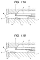
- Figs. 11A and 11B are sectional views taken along
the direction of one liquid flow path of a liquid
discharge head according to the first embodiment of the
present invention, where Fig. 11A relates to a
configuration of covering the whole heat generating
element with the free end of a movable member and Fig.
11B relates to a configuration of separating a heat
generating element from a movable member;
- Fig. 12 is a sectional view taken along the
direction of one liquid flow path of a liquid discharge
head according to the first variation of the first
embodiment of the present invention;
- Fig. 13 is a sectional view taken on line 13-13 of
Fig. 12;
- Fig. 14 is a sectional view taken along the
direction of one liquid flow path of a liquid discharge
head according to the second variation of the first
embodiment of the present invention;
- Fig. 15 is a sectional view taken on line 15-15 of
Fig. 14;
- Fig. 16 is a sectional view taken along the
direction of one liquid flow path of a liquid discharge
head according to the second variation of the first
embodiment of the present invention;
- Fig. 17 is a sectional view taken on line 17-17 of
Fig. 16;
- Fig. 18 is an illustration of an example of side-shooter
type liquid discharge head corresponding to the
configuration of a liquid discharge head according to
the first embodiment of the present invention;
- Figs. 19A and 19B are vertically sectional views
of a liquid discharge head according to the first
embodiment of the present invention, where Fig. 19A
relates to an example with a protective film and Fig.
19B relates to an example without a protective film;
- Fig. 20 is a sectional view taken along the
direction of one liquid flow path of a liquid discharge
head according to the second embodiment of the present
invention;
- Fig. 21 is a sectional view taken on line 21-21 of
Fig. 20;
- Fig. 22 is a sectional view taken on line 22-22 of
Fig. 20;
- Fig. 23 is a sectional view of a flow path for
explaining the "linear communication state";
- Figs. 24A and 24B are illustrations of the
discharge operation of the liquid discharge head of the
structure shown in Figs. 20 to 22, expressed in terms
of sectional views taken along the direction of one
liquid flow path and divided into characteristic
phenomena;
- Figs. 25A and 25B are illustrations of the
discharge operation subsequent to that of Figs. 24A and
24B, expressed in terms of sectional views taken along
the direction of one liquid flow path of a liquid
discharge head;
- Figs. 26A and 26B are illustrations of the
discharge operation subsequent to that of Figs. 25A and
25B, expressed in terms of sectional views taken along
the direction of one liquid flow path of a liquid
discharge head;
- Figs. 27A and 27B are sectional views taken along
the direction of one liquid flow path of a liquid
discharge head according to the second embodiment of
the present invention, where Fig. 27A relates to a
configuration of covering the whole heat generating
element with the free end of a movable member and Fig.
27B relates to a configuration of separating a heat
generating element from a movable member;
- Fig. 28 is a sectional view taken along the
direction of one liquid flow path of a liquid discharge
head according to the first variation of the second
embodiment of the present invention;
- Fig. 29 is a sectional view taken on line 29-29 of
Fig. 28;
- Fig. 30 is a sectional view taken along the
direction of one liquid flow path of a liquid discharge
head according to the first variation of the second
embodiment of the present invention;
- Fig. 31 is a sectional view taken on line 31-31 of
Fig. 30;
- Figs. 32A, 32B, 32C and 32D are illustrations of
individual parts of a liquid discharge head according
to the second variation of the second embodiment of the
present invention;
- Figs. 33A, 33B and 33C are illustrations of
various examples of flow path structures passing from
the liquid supply port to the liquid flow path in the
free end part of a movable member of a liquid discharge
head according to the third variation of the second
embodiment of the present invention, expressed in terms
of sectional views;
- Fig. 34 is an illustration of an example of side-shooter
type liquid discharge head corresponding to the
configuration of a liquid discharge head according to
the second embodiment of the present invention;
- Figs. 35A and 35B are vertically sectional views
of a liquid discharge head according to the second
embodiment of the present invention, where Fig. 35A
relates to an example with a protective film and Fig.
35B relates to an example without a protective film;
- Fig. 36 is a sectional view taken along the
direction of one liquid flow path of a liquid discharge
head according to the third embodiment of the present
invention;
- Fig. 37 is a sectional view taken on line 37-37 of
Fig. 36;
- Fig. 38 is a sectional view taken on line 38-38 of
Fig. 36;
- Fig. 39 is a plan view of a movable member in the
liquid discharge head shown in Figs. 36 to 38;
- Figs. 40A and 40B are manners of the liquid
discharge head shown in Figs. 36 to 38 in which
remaining bubble staying in the liquid flow path under
a movable member;
- Fig. 41 is a sectional view of a flow path for
explaining the "linear communication state";
- Figs. 42A and 42B are illustrations of the
discharge operation of the liquid discharge head of the
structure shown in Figs. 36 to 38, expressed in terms
of sectional views taken along the direction of one
liquid flow path and divided into characteristic
phenomena;
- Figs. 43A and 43B are illustrations of the
discharge operation subsequent to that of Figs. 42A and
42B, expressed in terms of sectional views taken along
the direction of one liquid flow path of a liquid
discharge head;
- Figs. 44A and 44B are illustrations of the
discharge operation subsequent to that of Figs. 43A and
43B, expressed in terms of sectional views taken along
the direction of one liquid flow path of a liquid
discharge head;
- Figs. 45A and 45B are sectional views taken along
the direction of one liquid flow path of a liquid
discharge head according to the third embodiment of the
present invention, where Fig. 45A relates to a
configuration of covering the whole heat generating
element with the free end of a movable member and Fig.
45B relates to a configuration of separating a heat
generating element from a movable member;
- Fig. 46 is a sectional view taken along the
direction of one liquid flow path of a liquid discharge
head according to the first variation of the third
embodiment of the present invention;
- Fig. 47 is a sectional view taken on line 47-47 of
Fig. 46;
- Fig. 48 is a sectional view taken on line of 48-48
shifted to the side of a top board 2 at the point Y1
from the discharge port center of Fig. 46;
- Fig. 49 is a plan view of a movable member in the
liquid discharge head shown in Figs. 46 to 48;
- Fig. 50 is a sectional view taken along the
direction of one liquid flow path of a liquid discharge
head according to the second variation of the third
embodiment of the present invention;
- Fig. 51 is a sectional view taken on line 51-51 of
Fig. 50;
- Fig. 52 is a sectional view taken along the
direction of one liquid flow path of a liquid discharge
head according to the second variation of the third
embodiment of the present invention;
- Fig. 53 is a sectional view taken on line 53-53 of
Fig. 52;
- Figs. 54A, 54B, 54C and 54D are illustrations of a
liquid discharge head according to the third variation
of the third embodiment of the present invention;
- Fig. 55 is a sectional view taken along the
direction of one liquid flow path of a liquid discharge
head according to the fourth embodiment of the present
invention;
- Fig. 56 is a sectional view taken along the
direction of one liquid flow path of a liquid discharge
head according to a fourth embodiment of the present
invention;
- Fig. 57 is a sectional view taken along the
direction of one liquid flow path of a liquid discharge
head according to the present invention for the
explanation of a forcible suction recovering operation;
- Fig. 58 is a sectional view taken along the
direction of one liquid flow path of a liquid discharge
head according to the fifth embodiment of the present
invention;
- Fig. 59 is a sectional view taken on line 59-59 of
Fig. 58;
- Fig. 60 is a sectional view taken on line 60-60 of
Fig. 58;
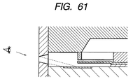
- Fig. 61 is a sectional view of a flow path for
explaining the "linear communication state";
- Figs. 62A and 62B are illustrations of the
discharge operation of the liquid discharge head of the
structure shown in Figs. 58 to 60, expressed in terms
of sectional views taken along the direction of one
liquid flow path and divided into characteristic
phenomena;
- Figs. 63A and 63B are illustrations of the
discharge operation subsequent to that of Figs. 62A and
62B, expressed in terms of sectional views taken along
the direction of one liquid flow path of a liquid
discharge head;
- Figs. 64A and 64B are illustrations of the
discharge operation subsequent to that of Figs. 63A and
63B, expressed in terms of sectional views taken along
the direction of one liquid flow path of a liquid
discharge head;
- Figs. 65A and 65B are sectional views taken along
the direction of one liquid flow path of a liquid
discharge head according to the fifth embodiment of the
present invention, where Fig. 65A relates to a
configuration of covering the whole heat generating
element with the free end of a movable member and Fig.
65B relates to a configuration of separating a heat
generating element from a movable member;
- Figs. 66A and 66B are illustrations of a suction
recovery operation of the liquid discharge head of the
structure shown in Figs. 58 to 60, expressed in terms
of sectional views taken along the direction of one
liquid flow path;
- Figs. 67A and 67B are illustrations of the
recovery operation subsequent to that of Figs. 66A and
66B, expressed in terms of sectional views taken along
the direction of one liquid flow path of a liquid
discharge head;
- Fig. 68 is a sectional view taken along the
direction of one liquid flow path of a liquid discharge
head according to the first variation of the fifth
embodiment of the present invention;
- Fig. 69 is a sectional view taken on line 69-69 of
Fig. 68;
- Fig. 70 is a sectional view taken along the
direction of one liquid flow path of a liquid discharge
head according to the first variation of the fifth
embodiment of the present invention;
- Fig. 71 is a sectional view taken on line 71-71 of
Fig. 70;
- Figs. 72A, 72B, 72C and 72D are illustrations of
individual parts of a liquid discharge head according
to the third variation of the fifth embodiment of the
present invention;
- Fig. 73 is an illustration of an example of side-shooter
type liquid discharge head corresponding to the
configuration of a liquid discharge head according to
the fifth embodiment of the present invention;
- Fig. 74A is a vertically sectional view of a
liquid discharge head according to the fifth embodiment
with a protective film;
- Fig. 74B is a vertically sectional view of a
liquid discharge head according to the fifth embodiment
without a protective film;
- Fig. 75 is a sectional view taken along the
direction of one liquid flow path of a liquid discharge
head according to the sixth embodiment of the present
invention;
- Fig. 76 is a sectional view taken on line 76-76 of
Fig. 75;
- Fig. 77 is a sectional view taken on line 77-77 of
Fig. 75;
- Fig. 78 is a manner of the liquid discharge head
shown in Figs. 75 to 77 in which remaining bubble
staying in the liquid flow path under a movable member
moves to the side of a common liquid supply chamber
through the communication part H;
- Fig. 79 is a sectional view of a flow path for
explaining the "linear communication state";
- Figs. 80A and 80B are illustrations of the
discharge operation of the liquid discharge head of the
structure shown in Figs. 75 to 77, expressed in terms
of sectional views taken along the direction of one
liquid flow path and divided into characteristic
phenomena;
- Figs. 81A and 81B are illustrations of the
discharge operation subsequent to that of Figs. 80A and
80B, expressed in terms of sectional views taken along
the direction of one liquid flow path of a liquid
discharge head;
- Figs. 82A and 82B are illustrations of the
discharge operation subsequent to that of Figs. 81A and
81B, expressed in terms of sectional views taken along
the direction of one liquid flow path of a liquid
discharge head;
- Figs. 83A and 83B are sectional views taken along
the direction of one liquid flow path of a liquid
discharge head according to the sixth embodiment of the
present invention, where Fig. 83A relates to a
configuration of covering the whole heat generating
element with the free end of a movable member and Fig.
83B relates to a configuration of separating a heat
generating element from a movable member;
- Fig. 84 is a sectional view taken along the
direction of one liquid flow path of a liquid discharge
head according to the first variation of the sixth
embodiment of the present invention;
- Fig. 85 is a sectional view taken along the
direction of one liquid flow path of a liquid discharge
head according to the second variation of the sixth
embodiment of the present invention;
- Fig. 86 is a sectional view taken on line 86-86 of
Fig. 85;
- Fig. 87A is a view of a liquid discharge head
according to the third variation of the sixth
embodiment of the present invention;
- Fig. 87B is a sectional view taken on line 87B-87B
of Fig. 87A;
- Fig. 87C is a sectional view taken on line 87B-87B
of Fig. 87A;
- Fig. 87D is a sectional view taken on line 87C-87C
of Fig. 87A;
- Fig. 88 is an illustration of an example of side-shooter
type liquid discharge head corresponding to the
configuration of a liquid discharge head according to
the sixth embodiment of the present invention;
- Fig. 89A is a vertically sectional view of a
liquid discharge head according to the present
invention with a protective film;
- Fig. 89B is a vertically sectional view of a
liquid discharge head according to the present
invention without a protective film;
- Fig. 90 is a sectional view taken along the
direction of one liquid flow path of a liquid discharge
head according to the seventh embodiment of the present
invention;
- Fig. 91 is a sectional view taken on line 91-91 of
Fig. 90;
- Fig. 92 is a sectional view taken on line 92-92 of
Fig. 90;
- Fig. 93 is a sectional view of a flow path for
explaining the "linear communication state";
- Figs. 94A and 94B are illustrations of the
discharge operation of the liquid discharge head of the
structure shown in Figs. 90 to 92, expressed in terms
of sectional views taken along the direction of one
liquid flow path and divided into characteristic
phenomena;
- Figs. 95A and 95B are illustrations of the
discharge operation subsequent to that of Figs. 94A and
94B, expressed in terms of sectional views taken along
the direction of one liquid flow path of a liquid
discharge head;
- Figs. 96A and 96B are illustrations of the
discharge operation subsequent to that of Figs. 95A and
95B, expressed in terms of sectional views of a liquid
discharge head taken along the direction of one liquid
flow path;
- Fig. 97A is a sectional view taken along the
direction of one liquid flow path of a liquid discharge
head according to the seventh embodiment of the present
invention, where the whole heat generating element is
covered with the free end of a movable member;
- Fig. 97B is a sectional view taken along the
direction of one liquid flow path of a liquid discharge
head according to the seventh embodiment of the present
invention, where the heat generating element is
separated from a movable member;
- Fig. 98 is a sectional view taken along the
direction of one liquid flow path of a liquid discharge
head according to the first variation of the seventh
embodiment of the present invention;
- Fig. 99 is a sectional view taken on line 99-99 of
Fig. 98;
- Fig. 100 is a sectional view taken on line of 100-100
shifted to the side of a top board 2 at the point
Y1 from the discharge port center of Fig. 98;
- Fig. 101 is a sectional view taken along the
direction of one liquid flow path of a liquid discharge
head according to the second variation of the seventh
embodiment of the present invention;
- Fig. 102 is a sectional view taken on line 102-102
of Fig. 101;
- Fig. 103 is a sectional view taken along the
direction of one liquid flow path of a liquid discharge
head according to the second variation of the seventh
embodiment of the present invention;
- Fig. 104 is a sectional view taken on line 104-104
of Fig. 103;
- Fig. 105A is a view of a liquid discharge head
according to the third variation of the seventh
embodiment of the present invention;
- Fig. 105B is a sectional view taken on line 105B-105B
of Fig. 105A;
- Fig. 105C is a sectional view taken on line 105C-105C
of Fig. 105A;
- Fig. 105D is a sectional view taken on line 105D-105D
of Fig. 105A;
- Fig. 106 is an illustration of an example of side-shooter
type liquid discharge head corresponding to the
configuration of a liquid discharge head according to
the seventh embodiment of the present invention;
- Fig. 107A is a vertically sectional view of a
liquid discharge head according to the seventh
embodiment of the present invention with a protective
film;
- Fig. 107B is a vertically sectional view of a
liquid discharge head according to the seventh
embodiment of the present invention without a
protective film;
- Fig. 108 is a sectional view taken along the
direction of one liquid flow path of a liquid discharge
head according to the eighth embodiment of the present
invention;
- Fig. 109 is a sectional view taken on line 109-109
of Fig. 108;
- Fig. 110 is a sectional view taken on line 110-110
of Fig. 108;
- Fig. 111 is a sectional view of a flow path for
explaining the "linear communication state";
- Figs. 112A and 112B are illustrations of the
discharge operation of the liquid discharge head of the
structure shown in Figs. 108 to 110, expressed in terms
of sectional views taken along the direction of one
liquid flow path and divided into characteristic
phenomena;
- Figs. 113A and 113B are illustrations of the
discharge operation subsequent to that of Figs. 112A
and 112B, expressed in terms of sectional views of a
liquid discharge head taken along the direction of one
liquid flow path;
- Figs. 114A and 114B are illustrations of the
discharge operation subsequent to that of Figs. 113A
and 113B, expressed in terms of sectional views of a
liquid discharge head taken along the direction of one
liquid flow path;
- Fig. 115 is an illustration of the discharge
operation subsequent to that of Figs. 114A and 114B,
expressed in terms of sectional views of a liquid
discharge head taken along the direction of one liquid
flow path;
- Fig. 116A is a sectional view taken along the
direction of one liquid flow path of a liquid discharge
head according to the eighth embodiment of the present
invention, where the whole heat generating element is
covered with the free end of a movable member;
- Fig. 116B is a sectional view taken along the
direction of one liquid flow path of a liquid discharge
head according to the eighth embodiment of the present
invention, where the heat generating element is
separated from a movable member;
- Fig. 117 is a sectional view taken along the
direction of one liquid flow path of a liquid discharge
head according to variation of the eighth embodiment of
the present invention;
- Fig. 118 is a sectional view taken on line 118-118
of Fig. 117;
- Fig. 119 is a sectional view taken along the
direction of one liquid flow path of a liquid discharge
head according to variation of the eighth embodiment of
the present invention;
- Fig. 120 is a sectional view taken on line 120-120
of Fig. 119;
- Fig. 121 is an illustration of an example of side-shooter
type liquid discharge head corresponding to the
configuration of a liquid discharge head according to
the eighth embodiment of the present invention;
- Fig. 122A is a vertically sectional view of a
liquid discharge head according to the eighth
embodiment of the present invention with a protective
film;
- Fig. 122B is a vertically sectional view of a
liquid discharge head according to the eighth
embodiment of the present invention without a
protective film;
- Figs. 123A, 123B, 123C, 123D and 123E are
illustrations of a isotropic growth state of a bubble;
- Fig. 124 is a graph showing a correlation between
a time change in bubble growth and the behavior of a
movable member for Areas A and B in steps of the
discharge operation;
- Fig. 125 is a graph showing a correlation between
a time change in bubble growth and the behavior of a
movable member in a liquid discharge head according to
the present invention, of a configuration that the
whole heat generating element is covered with the free
end of the movable member;
- Fig. 126 is a graph showing a correlation between
a time change in bubble growth and the behavior of a
movable member in a liquid discharge head according to
the present invention, of a configuration that the heat
generating element is remote from the free end of the
movable member;
- Fig. 127 is a graph showing a correlation between
the area of a heat generating element and the discharge
amount of ink;
- Fig. 128 is a sectional view of an element
substrate to be used for liquid discharge heads
according to various embodiments;
- Fig. 129 is a typical sectional view of an element
substrate sectioned in such a manner as to divide its
main elements vertically shown in Fig. 128;
- Fig. 130 is a graph of the wave form of a voltage
for driving the heat generating element used in the
present invention;
- Fig. 131 is a perspective view showing the outline
configuration of a liquid discharge apparatus with a
liquid discharge head according to the present
invention loaded;
- Fig. 132 is a block diagram of the whole apparatus
helpful in understanding a liquid discharge method
according to the present invention for performing the
liquid discharge recording by using a liquid discharge
head according to the present invention; and
- Fig. 133 is a sectional view showing the arranging
manner of a movable member in a conventional liquid
discharge head.
-
DESCRIPTION OF THE PREFERRED EMBODIMENTS
-
Next, embodiments of the present invention will be
described referring to the drawings.
(First Embodiment)
-
Fig. 1 is a sectional view taken along one liquid
flow path of a liquid discharge head according to the
first embodiment of the present invention; Fig. 2 is a
sectional view taken along line 2-2 of Fig. 1; and Fig.
3 is a sectional view taken along line 3-3 shifted to
the side of a top board 2 at the point Y1 from the
discharge port of Fig. 1.
-
In the liquid discharge head of the form of
multiple liquid paths-a common chamber shown in Figs. 1
to 3, an element substrate 1 and a top board 2 are
fastened via a liquid path side wall 10 in a stacked
state and a liquid flow path 3 communicating to a
discharge port 7 at one end and closed at the other end
is formed between both plates 1 and 2. A great number
of such liquid flow paths 3 are provided at one head.
Besides, in the element substrate 1, heat generating
elements 4 such as electro-thermal converter elements
as bubble generator means for generating bubble in
liquids filled up at liquid flow paths 3 are disposed
to individual liquid flow paths 3. In the vicinity
area at the contact surface between a heat generating
element 4 and a discharge liquid, there is present a
bubble generating area 11 where a heat generating
element 4 is rapidly heated to generate bubble in a
discharge liquid.
-
In each of many liquid flow paths 3, a liquid
supply port 5 formed at a supply part forming member 5A
is disposed and a common liquid supply chamber 6
communicating to all individual liquid supply ports 5
is provided. In other words, a form of being branched
from a single common liquid supply chamber 6 into many
liquid flow paths 3 is observed and an amount of liquid
corresponding to that of liquid discharged from the
discharge port 7 communicating to each liquid flow path
3 is received from this common liquid supply chamber 6.
-
Between a liquid supply port 5 and a liquid flow
path 3, a movable member 8 is provided an infinitesimal
gap apart from the opening area S of the liquid supply
port 5. The movable member 8 is situated in parallel
with the element substrate 1. One end of the movable
member 8 is a free end 8B situated at the side of a
heat generating element 4 of the element substrate 1,
whereas the other end is supported by a fixed member 9.
Closed by this fixed member 9 is the port opposite from
the discharge port 7 of the liquid flow path 3.
-
In a standstill state of the movable member 8 as
shown in Fig. 1, the tip end of the movable member 8 at
the side of the free end 8B is in contact with the
supply part forming member 5A serving for a member for
forming the liquid supply port 5 by means of its
elastic force. Thus, a portion of the supply part
forming member 5A at the side of the discharge port 7
constitutes a stopper part 5b pressed by the movable
member 8 which the end of the side of free end 8B of
the movable member 8 is in butt contact with. The
portion of the movable member 8 between the portion in
contact with the stopper part 5b and the portion fixed
to the fixing part 9 is only an infinitesimal gap apart
from the liquid supply port 5 and the infinitesimal gap
between the movable member 8 and the liquid supply port
5 gradually broadens from the free end 8B toward the
side of the fulcrum 8A.
-
The area enclosed by at least the free end part of
the movable member 8 and the both lateral parts
adjacent thereto becomes greater than the opening area
S of the liquid supply port 5 (See Fig. 3) and an
infinitesimal gap β is present between the lateral part
of the movable member 8 and both the respective flow
path side walls 10 (See Fig. 2). The above supply part
forming member 5A is apart via a gap γ from the movable
member 8 as shown in Fig. 2. Gaps β and γ depend on
the pitch of the flow path, but a great value of γ
makes it easy for the movable member 8 to shut off the
opening area S and a large value of β makes it easy for
the movable member 8 to move to the side of the element
substrate 1 with the disappearance of bubble rather
than the stationary state of being situated via a gap
from the liquid supply port 5. With this embodiment,
gaps between the fulcrum 8A of the movable member 8 and
the liquid supply port 5, concretely the gap a shown in
Fig. 2 was set to 3 µm, the gap β was set to 3 µm and
the gap γ was set to 4 µm.
-
Besides, in width with the flow path side wall 10,
the movable member 8 has a greater width W1 than the
width W2 of the above opening area S, which is wide
enough to seal the opening area S. On an extension of
the end part at the side of the free end of the
continuous part continuous concerning the crossing
direction of movable members to flow paths, the fulcrum
8A of the movable member 8 prescribes the upstream side
end part of the opening area S of the liquid supply
port 5 (See Fig. 3). In this embodiment, as shown in
Figs. 2 and 3, the portion of the supply part forming
member 5A along the movable member 8 is set less wide
than the flow path side wall 10 itself and the supply
part forming member 5A is stacked on the flow path side
wall 10. Incidentally, the supply part forming member
5A is set equal in width to the flow path side wall 10
at the side of discharge port 7 rather than at the side
of the free end 8B of the movable member 8 as shown in
Fig. 3.
-
By these, whereas the movable member 8 is movable
without a frictional resistance in the liquid flow path
3, its displacement toward the side of the opening area
S can be regulated by the peripheral part thereof.
Thereby, the opening area S can be substantially
blocked to prevent the liquid flow from inside the
liquid flow path 3 to the common liquid supply chamber
6 from being reversed, while on the other hand, the
movement from the substantially sealed state to the
refillable state becomes possible to the liquid flow
path side with the disappearance of bubble. In a state
that the movable member 8 is at rest, the tip end of
the movable member 8 at the side of the free end 8B is
in contact with the stopper part 5b of the supply part
forming member 5A and moreover an infinitesimal gap is
present between the lateral part in a portion of the
movable member 8 at the side of its fulcrum 8A and the
supply part forming member 5A, while there is a slight
communication between the liquid supply port 5 and the
liquid flow path 3 through the infinitesimal gap.
-
Incidentally, the opening area S is a substantial
area for supplying a liquid from the liquid supply port
5 toward the liquid flow path 3 and an area enclosed by
the three sides of the liquid supply port 5 and the end
part 9A of the fixed member 9 in this embodiment as
shown in Figs. 1 and 3.
-
Besides, as shown in Fig. 4, this embodiment,
having no such an obstacle as valve between the heat
generating element 4 as an electro-thermal converter
and the discharge port 7, is in a "straight
communicable state" with the structure of a straight
flow path kept to a liquid flow. This becomes well
preferable if an ideal state of stabilizing the
discharge conditions such as discharge direction and
discharge rate of discharge drops at an extremely high
level is formed by matching the propagating direction
of a pressure wave occurring at the generation of
bubble with the accompanying flow direction and the
discharge direction of the liquid straightly. In this
present invention, it is only necessary as one
definition for attaining or approaching to this ideal
state to choose a construction of directly combining
the discharge port 7 with the side of the discharge
port 7 (downstream side) of a heat generating element
4, in particular, the heat generating element 4
influential to the side of the discharge port 7 of
bubble, by using a straight line, which means an
observable state of the heat generating element 4, in
particular, the downstream side thereof, when viewed
from the exterior of the discharge port 7 in absence of
a liquid in the liquid flow path 3 (See Fig. 4).
-
Next, the movement of the movable member 8 in a
liquid discharge port according to the present
invention will be described in detail. Figs. 5A and 5B
to Figs. 8A and 8B show not only a liquid discharge
head in a sectional view taken along a liquid flow path
to illustrate the movement of a movable member 8 in the
liquid discharge head of such a structure as shown in
Figs. 1 to 3, but a characteristic phenomenon divided
in 8 steps of Figs. 5A to 8B.
-
Fig. 5A shows a state prior to the application of
an energy such as electric energy to a heat generating
element 4 and before the heat generating element 4
generates heat. In this state, an infinitesimal gap
(not greater than 10 µm) is present apart from the
formed surface of the liquid supply port 5 over an
extent from the center part to the fulcrum side in the
movable member 8 provided between the liquid supply
port 5 and the liquid flow path 3.
-
Here, it is important that a movable member 8 is
provided at a position facing nearly a half of the
upstream side of a bubble generated by heat of a heat
generating element 4, the free end part of the movable
member 8 and the stopper part 5b of a supply part
forming member 5A are disposed above the center of a
bubble generating area 11 and the movable member 8 is
in contact with the stopper part 5b before the
generation of bubble by dint of a liquid flow path
structure, the disposing position of the movable member
8 and an elastic force of the movable member 8.
-
Fig. 5B shows a state that part of the liquid
filling the liquid flow path 3 is heated by a heat
generating element 4, film boiling occurs on the heat
generating element 4 and bubble 21 grow isotropically.
Here, the phrase "the growth of a bubble is isotropic"
means a state that the growing rate of a bubble toward
the normal of a bubble surface is almost equal in
positions of the bubble surface.
-
In an isotropic growth process of a bubble 21 at
this initial stage of bubble generation, the
displacement of an extent of the movable member 8
between the portion in contact with the stopper part 5b
and the portion near the fulcrum 8A toward the side of
the liquid supply port 5 brings the movable member 8
into close contact with the peripheral portion of the
liquid supply port 5 to block up the liquid supply port
5, so that the interior of the liquid flow path 3 comes
substantially into a sealed state except the discharge
port 7. By the way, a period while the sealing state
is established and maintained may lie within a period
from the application of a driving voltage to a heat
generating element 4 to the completion of an isotropic
growth of a bubble 21. Besides, in this sealed state,
the inertance (difficulty in moving when a still water
begins to move suddenly) from the center of the heat
generating element 4 to the side of the liquid supply
port amounts substantially to an infinity in the liquid
flow path 3. At this time, the inertance from the heat
generating element 4 to the side of the liquid supply
port approaches more to an infinity the greater
distance is taken between the heat generating element 4
and the movable member 8. Furthermore, at this time,
hl is let to be a maximum displacement of a portion
near the fulcrum of the movable member 8 to the side of
the liquid supply port 5.
-
In this embodiment, contact of the free end of the
movable member 8 with the stopper part 5b in a
stationary state as mentioned above shortens the time
from the generation of bubble till the blockage of the
liquid supply port 5 with the movable member 8 in
comparison with the case where the free end of the
movable member 8 is remote from the stopper part 5b in
a stationary state, thus suppressing the move of ink
from the liquid flow path 3 to the liquid supply port 5
at the greatest possible. Thereby, loss of discharge
power due to the move of ink from the liquid flow path
3 to the liquid supply port 5 is lessened in the
discharge operation and the discharge efficiency of a
liquid discharge head is improved. Besides, along with
this, a rapid transit is enabled from the isotropic
growth of a bubble to the period of partial growth and
partial shrinkage while the portion at the side of the
discharge port 7 in the bubble 21 grows and the portion
at that of the liquid supply port 5 in the bubble 21
shrinks.
-
Fig. 6A shows a state of a bubble 21 keeping to
grow. In this state, since the interior of the liquid
flow path 3 is substantially in a sealed state except
the discharge port 7, the flow of a liquid does not
reach the side of the liquid supply port 5.
Accordingly, the bubble 21 can expand greatly to the
side of the discharge port 7, but does not so much to
that of the liquid supply port 5. And, at the side of
the discharge port 7 in the bubble generating area 11,
the bubble growth continues, but by contraries, the
bubble growth stops at that of the liquid supply port 5
in the bubble generating area 11. In brief, this
bubble growth stop state becomes a maximum bubbling
state at the side of the liquid supply port 5 in the
bubble generating area 11. Vr is let to be the
bubbling volume of this time.
-
At this time, the bubble growth of Area B stops
and a force pressing the movable member 8 to the liquid
supply port 5 weakens. In this way, by the elastic
force of the movable member 8, the vicinity of the
center part of the movable member 8 is just about to
begin a downward displacement toward a stationary
state.
-
Here, referring to Figs. 123A-123E, the growing
process of a bubble in Figs. 5A, 5B and 6A will be
described in detail. On heating a heat generating
element 4, as shown in Fig. 123A, an initial boiling
takes place on the heat generating element 4, then
changing to a film boiling in which a filmy bubble
covers over the heat generating element 4 as shown in
Fig. 123B. And, the bubble of a film boiling state
keeps growing isotropically as shown in Figs. 123B and
123C (such an isotropically growing state of a bubble
is referred to as semi-pillow state). When the
interior of the liquid flow path 3 turns substantially
into a sealed state except the discharge port 7 as
shown in Fig. 5B, however, the move of a liquid toward
the upstream side is disabled, so that part of a bubble
in the semi-pillow state at the upstream side (side of
the liquid supply port 5) becomes unable to grow so
much and the rest portion of downstream side (side of
the discharge port 7) grows greatly. This state is
shown in Fig. 6A or Figs. 123D and 123E. Here, for the
convenience of explanation, an area in which no bubble
grows on the heat generating element 4 and an area at
the side of the discharge port 7 in which a bubble
grows when heating the heat generating element 4 are
designated with Area B and Area A, respectively.
Incidentally, in Area B shown in Fig. 123E, the
bubbling volume reaches a maximum and Vr is let to be
the bubbling volume of this time.
-
Next, Fig. 6B shows a state at which the growth of
a bubble continues in Area A and the shrinkage of a
bubble has begun in Area B. In this state, a bubble
grows greatly toward the side of the discharge port in
Area A and the volume of a bubble begins to decrease in
Area B. Thereby, an extent between the portion in
contact with the stopper part 5b and the portion fixed
to the fixed member 9 of the movable member 8 begins to
be displaced downward to the stationary state position
under action of the recovering force due to its
rigidity and the disappearing force of a bubble in Area
B. As a result, the liquid supply port 5 opens near
the fulcrum part of the movable member 8, while the
common liquid supply chamber 6 and the liquid flow path
3 turn into a communicable state through an
infinitesimal gap between the portion near the fulcrum
part of the movable member 8 and the liquid supply port
5.
-
At this time, the center part of the movable
member 8 begins the downward displacement at first and
subsequently the free end of the movable member 8 is
displaced downward. For this reason, the movable
member 8 is displaced at a second or higher order
vibrational mode. Referring to Figs. 9 and 10, higher
order vibrational modes will be described below.
-
Fig. 7A shows a state that the free end 8B also
starts the downward displacement subsequently to the
center part of the movable member 8 and the refill of a
liquid from the liquid supply port 5 begins in
consequence. Accompanying the refill of a liquid, the
bubble of Area B begins to shrink, but the bubble of
Area A still remains growing. At this time, since the
vibration of the movable member 8 is of a higher mode,
the displacement velocity of the free end 8B is great.
-
Here, referring to Figs. 9 and 10, higher order
vibrational modes will be described in detail. The
first order vibrational mode of a cantilever with one
end being free is shown in Fig. 9 and the second order
vibrational mode is shown in Fig. 10. Compared with
the first order vibrational mode, the second order
vibrational mode has a large natural frequency and also
exhibits a great displacement at the free end. Thus,
in this embodiment, vibrating the movable member 8 at
the second order vibrational mode makes it possible to
shorten the duration of downward displacement in the
movable member 8 and to complete the refill for a short
time while increasing the displacement of the free end
in the movable member 8.
-
Fig. 7B shows a state that the bubble 21 has grown
to a nearly maximum. At this state, a bubble in Area A
has grown to a maximum and almost all bubbles in Area B
disappear by the refill from the liquid supply port 5.
Furthermore, the downward displacement rate of the free
end in the movable member 8 decreases and its
displacement is just about to stop, whereas the
vicinity of the center part of the movable member 8 has
already started the upward displacement. Vf is let to
be a maximum bubble volume in Area A at this time.
Besides, the discharge liquid under discharge from the
discharge port 7 is still tied to a meniscus with a
long tail drawn.
-
Fig. 8A shows the bubble disappearing step of a
bubble in Area A. Along with the refill of a liquid
from the liquid supply port 5, the free end 8B of the
movable member 8 starts the upward displacement quickly
and the movable member 8 is about to recover to a
stationary state.
-
Fig. 8B corresponds to the stage of a bubble
disappearing step alone at which the growth of the
bubble 21 stops. Right after the bubble growth changes
into the bubble disappearance in Area A, the shrinking
energy of the bubble 21 acts as a force of moving the
liquid near the discharge port 7 toward the upstream
direction as a result of total balance. Thus, the
meniscus is pulled into the liquid flow path 3 from the
discharge port 7 at this point, thus cuts off the
liquid pole combined with the discharge bubble liquid
droplet swiftly by a strong force. On the other hand,
along with the shrinkage of a bubble, a liquid flows
rapidly from the common liquid supply chamber 6 via the
liquid supply port 5 into the liquid flow path 3 in a
large current. Thereby, the flow rapidly pulling the
meniscus into the liquid flow path 3 lowers abruptly,
so that the meniscus begins to return to the position
prior to the bubbling at a relatively low speed and
therefore the convergency of vibration of the meniscus
is very good in comparison with the liquid discharge
scheme equipped with no movable member according to the
present invention. Incidentally, h2 (See Fig. 7B) is
let to be a maximum displacement of the free end of the
movable member 8 to the side of the bubble generating
area 11.
-
Finally, when the bubble 21 completely disappears,
the movable member 8 also recovers to the stationary
state position shown in Fig. 5A. Toward this state,
the movable member 8 is displaced upward under action
of its elastic force (along Arrowhead A of solid line
in Fig. 8A). Besides, in this state, the meniscus has
already recovered near the discharge port 7. Here, as
mentioned above, an infinitesimal gap is present
between the fulcrum part of the movable member 8 and
the liquid supply port 5, while the liquid supply port
5 and the liquid flow path 3 communicate with each
other through the infinitesimal gap even in a state
that the movable member 8 stands completely still.
Thereby, even if the movable member 8 comes to a
standstill before the meniscus completely recovers or
if the movable member 8 comes to a standstill in a
state that the meniscus protrudes from the discharge
port 7 by the overshoot during the refill of ink into
the liquid flow path 3, ink moves through an
infinitesimal gap between the fulcrum part of the
movable member 8 and the liquid supply port 5, thereby
enabling the meniscus to be displaced to a proper
position.
-
Next, a correlation between the time volume change
of a bubble in Area A as well as Area B shown in Figs.
5A and 5B to 8A and 8B and the behavior of the movable
member 8 will be described referring to Fig. 124. Fig.
124 is a graph representing the relevant correlation,
Curve A shows the time volume change of a bubble in
Area A and Curve B shows the time volume change of a
bubble in Area B.
-
As shown in Fig. 124, the time volume change of a
bubble in Area A draws a parabola having a maximum. In
other words, the volume of a bubble increases with the
lapse of time from the start of bubbling till the
disappearance of the bubble and reaches a maximum at a
certain point, then decreasing. On the other hand,
with respect to Area B, the time taken from the start
of bubbling till the disappearance of the bubble is
shorter, the maximum growth volume of the bubble is
smaller and the time of arrival at the maximum growth
is shorter than in Area A. In brief, the time of
arrival at the maximum growth and the growth volume
change of a bubble differ greatly and are smaller in
Area B.
-
Especially in Fig. 124, Curves A and B overlap
each other for the initial generation of the bubble,
because the volume of a bubble increases at the same
time change rate. Namely, the period that a bubble is
growing isotropically (in the form of semi-pillow)
comes into existence for the initial generation of the
bubble. Thereafter, though drawing an increasing curve
identical with Curve A till reaching a maximum, Curve B
branches from Curve A at a certain point and draws a
curve decreasing in the volume of the bubble. Namely,
a period that the time of a bubble decreases in Area B
though increasing in Area A (period of partial growth
and partial shrinkage) appears.
-
And, based on a manner of bubble growth as
mentioned above, the movable member 8 takes the
following behavior in a form that part of the heat
generating element 4 is covered with the free end of
the movable member 8 as shown in Fig. 1. Namely, for
the period (1) of Fig. 124, the portion of the movable
member between the free end and the vicinity of the
fulcrum is displaced up toward the liquid supply port.
For the period (2) of Fig. 124, the movable member is
in close contact with the liquid supply port and the
interior of the liquid flow path becomes substantially
a sealed state except the discharge port. The start of
this sealed state is carried out for a period that a
bubble grows isotropically. Next, for the period (3)
of Fig. 124, the portion of the movable member between
the free end and the vicinity of the fulcrum is
displaced down toward the stationary state position.
The opening start of the liquid supply port by this
movable member is carried out at the lapse of a given
time from the start of the period of partial growth and
partial shrinkage. Then, for the period (4) of Fig.
124, the movable member is further displaced downward
from the stationary state position. Next, for the
period (5) of Fig. 124, the downward displacement of
the movable member almost stops and the movable member
is in an equilibrium state at an open position.
Finally, for the period (6) of Fig. 124, the movable
member is displaced up toward the stationary state
position.
-
The correlation between such a bubble growth and
the behavior of the movable member is affected by the
relative position of the movable member to the heat
generating element. Such being the case, referring to
Figs. 11A and 11B, Fig. 125 and Fig. 126, a correlation
between the bubble growth and the behavior of a movable
member in the liquid discharge head equipped with the
movable member and the heat generating element disposed
in relative positions different from those of this
embodiment will be described.
-
Figs. 125 and 11A serve to explain a correlation
between the bubble growth and the behavior of a movable
member in a form that the whole heat generating element
is covered with the free end of the movable member,
Fig. 11A shows the relevant form and Fig. 125 is a
graph showing the correlation. When the overlapping
area of a heat generating element and a movable member
is large as shown in Fig. 11A, the period (1) of Fig.
125 becomes shorter than in the form of Fig. 1, the
liquid flow path comes into a sealed state in a short
time from heating the heat generating element and
accordingly this form is well preferable.
-
Incidentally, the behavior of a movable member in each
of the periods (1) to (6) in Fig. 125 is identical with
the behavior described referring to Fig. 124. Besides,
since a movable member becomes susceptible to a
decrease in the volume of a bubble on taking the form
of Fig. 11A, opening start of the liquid supply port by
this movable member is carried out immediately after
the start of the period of partial growth and partial
shrinkage as understood from the start point of the
period (3) of Fig. 125. Namely, the opening timing of
the movable member is earlier than in the form of Fig.
1. For a similar reason, the reason of the amplitude
of the movable member 8 increases.
-
Besides, Fig. 126 serves to explain a correlation
between the bubble growth and the behavior of a movable
member in a form that a heat generating element is
remote from the free end of a movable member, Fig. 11B
shows the relevant form and Fig. 126 is a graph showing
the correlation. When a movable member and a heat
generating element are separated from each other like
the form shown in Fig. 12B and Fig. 126, a movable
member is least subject to a decrease in the volume of
a bubble, so that opening start of the liquid supply
port by this movable member is carried out quite later
than the start of the period of partial growth and
partial shrinkage as understood from the start point of
the period (3) of Fig. 126. Namely, the opening timing
of the movable member is later than in the form of Fig.
1. For a similar reason, the reason of the amplitude
of the movable member decreases. Incidentally, the
behavior of a movable member in each of the periods (1)
to (6) in Fig. 126 is identical with the behavior
described referring to Fig. 124.
-
Meanwhile, the positional relation between the
movable member 8 and the heat generating element 4 is
helpful for the description of a general operation and
individual operations depend upon the position of the
free end of the movable member, the rigidity thereof
and the like.
-
Besides, letting Vf and Vr be the volume of a
growing bubble at the maximum at the side of the
discharge port 7 (bubble of Area A) in the bubble
generating area 11 and that of a growing bubble at the
maximum at the side of the liquid supply port 5 (bubble
of Area B) in the bubble generating area 11,
respectively, the relation of Vf > Vr holds true
permanently for a head according to the present
invention as evident from Figs. 124 to 126.
Furthermore, letting Tf and Tr be the life time (time
from the appearance of a bubble to the disappearance of
the bubble) of a growing bubble at the side of the
discharge port 7 (bubble of Area A) in the bubble
generating area 11 and that of a growing bubble at the
side of the liquid supply port 5 (bubble of Area B) in
the bubble generating area 11, respectively, the
relation of Tf > Tr holds true permanently for a head
according to the present invention. And, from a
relation as mentioned above, it follows that the
disappearing point of a bubble is situated at the side
of the discharge port 7 rather than near the center of
the bubble generating area 11.
-
Furthermore, with the present configuration of a
head, as understood also from Figs. 5B and 7B, there is
a relation that the maximum displacement h2 of the free
end of a movable member 8 toward the side of the bubble
generator means 4 along with the disappearance of a
bubble is greater than the maximum displacement h1 of
the fulcrum vicinity of the movable member 8 toward the
side of the liquid supply port 5 at the initial
generation of the bubble (h1 < h2). For example, h1 is
2 µm and h2 is 10 µm. Validity of this relation can
suppress the growth of a bubble toward behind a heat
generating element (opposite the discharge port) at the
initial generation of the bubble and can enhance that
of a bubble toward the front of the heat generating
element (toward the discharge port). Thereby, the
efficiency of converting the bubbling energy generated
on the heat generating element into the kinetic energy
of a droplet of a liquid flying from the discharge port
can be raised.
-
The head configuration and the liquid discharge
operation in this embodiment was described, but
according to such an embodiment, the growth component
to the downstream side and the growth component to the
upstream side of a bubble are unequal, the upstream
component nearly vanishes and the move of a liquid
toward the upstream side is suppressed. Since the move
of the liquid toward the upstream side is suppressed,
most of the bubble growth is directed toward the
discharge port without loss of the growth component to
the upstream side and the discharge power is improved
in leaps and bounds. Furthermore, the retreat of a
meniscus after the discharge decreases and its
protrusion from the orifice surface during the refill
decreases correspondingly. Accordingly, the meniscus
vibration is suppressed and a stable discharge becomes
performable at all driving frequencies from a low
frequency to a high frequency.
-
In a liquid discharge head according to the first
embodiment, as described in all these, at least the
free end of a movable member 8 is in contact with the
stopper part 5b of a supply part forming member 5A in a
standstill state of the movable member 8. Thereby,
during a period ranging from the appearance of a bubble
till the liquid flow path 3 is brought into an almost
sealed state by blocking the liquid supply port 5 with
the movable member 8, the move of ink from the liquid
flow path 3 to the liquid supply port 5 is suppressed
at the greatest possible. As a result, loss of the
discharge power due to the move of ink from the liquid
flow path 3 to the liquid supply port 5 decreases in
the ink discharge operation and the discharge
efficiency of the liquid discharge head is improved.
Besides, together with this, a rapid transit from the
isotropic growth of a bubble to the partial growth and
partial shrinkage period while the portion at the side
of the discharge port 7 of the bubble 21 grows and the
portion at the side of the liquid supply port 5 thereof
shrinks can be achieved.
-
Furthermore, since the vibration of the movable
member 8 belongs to a second or higher vibrational
mode, the natural frequency of the movable member 8 is
large, the movable member 8 rapidly opens and closes
and moreover the downward displacement is also great.
As a result, a great amount of refill in a short time
is enabled.
-
[First Variation] Fig. 12 is a sectional view
taken along one liquid flow path of a liquid discharge
head according to The first variation of the first
embodiment and Fig. 13 is a sectional view taken along
line Y-Y' shifted to the side of the top board 2 at the
point Y1 from the discharge port center of Fig. 1. A
liquid discharge head according to this variation
differs from the first embodiment chiefly in that, at
the initial state of a movable member being at rest,
the end of the movable member at the side of the free
end presses the peripheral portion of a liquid supply
port to bend the movable member. In Figs. 12 and 13,
like symbols are attached to constituents similar to
those of the first embodiment and hereinafter a
description will be made while centering on points
different from the first embodiment.
-
At the initial state of a movable member 8 being
at rest in a liquid discharge head according to this
modification, as shown in Fig. 12, the tip end of the
movable member 8 at the side of the free end 8B is in
contact with the supply part forming member 5A to press
the supply part forming member 5A and moreover the
movable member 8 is elastically bent convexly toward
the side of the liquid supply port 5 and is retained so
as to charge a stress. Namely, even at rest, the
movable member 8 applies a force to the supply part
forming member 5A with the aid of its elastic force and
in particular the tip end of the movable member 8 at
the side of the free end 8B is elastically bent
convexly toward the side of the liquid supply port 5.
-
With ink discharge operation in this liquid
discharge head, the movable member 8 is further bent
convexly toward the side of the liquid supply port 5 in
the case where film boiling occurs on the heat
generating element 4 and a bubble grows isotropically.
With a further bending of the movable member 8, an
extent of the moving member 8 between the portion in
contact with the stopper part 5b and the portion near
the fulcrum 8A is displaced upward and the movable
member 8 comes into close contact with the peripheral
portion of the liquid support port 5. Thereby, the
opening area S of the liquid supply port 5 is blocked
with the movable member 8 and the interior of the
liquid flow path 3 substantially comes into a sealed
state except the discharge port 7. At this time, since
the movable member 8 is convexly bent elastically
toward the upstream side before a bubble grows to a
maximum, dispersion in bubbling state due to dispersion
in heating characteristics of the heat generating
element 4, a change in ambient temperature or the like
is absorbed by the bending of the movable member 8. As
a result, dispersion in the discharge amount of ink
originating from dispersion in bubbling state caused by
the heat generating element 4, a change in ambient
temperature or the like is suppressed.
-
In the case of a liquid discharge head according
to this variation, no change but a convex bending of
the movable member 8 is made at the time of bubbling.
Accordingly, during the refill of ink into the liquid
flow path 3, a disappearing force of a bubble is added
to a recovering force of the movable member 31 as
energy for the downward displacement of the movable
member 8.
-
Furthermore, since the upward displacement of the
center part of the movable member 8 during the
isotropic growth of a bubble is greater than in the
first embodiment, the movable member 8 is displaced at
a higher vibrational mode than that of the first
embodiment. Accordingly, shortening the refill time is
enabled.
-
By these, the liquid flow to the upstream side is
regulated greatly not only to prevent the reverse
current or the pressure vibration of a liquid in the
supply path system as prohibiting the liquid cross talk
to an adjacent nozzle or a high-speed refill into the
liquid flow path 3 but to suppress the fluctuation of a
discharge amount also.
-
In the case of a liquid discharge head in such an
arrangement, the downward displacement of a movable
member 8 is small and the movable member 8 rapidly
transits to the stationary state position even if a
normal discharge operation of ink is carried out.
Thus, the amount of ink to be refilled into the liquid
flow path 3 is small, but the refill of ink into the
liquid flow path 3 is completed. Thereby, an
arrangement that a movable member 8 is elastically bent
in a standstill state can be effective for a liquid
discharge head for discharging an infinitesimal
discharge amount of ink.
-
[Second Variation] In a head structure according
to the first embodiment, since a position of the
movable member 8 remaining unjoined to the fixed member
9 (i.e., bent and rising) was not the same as the end
part 9A of the fixed member 9 as shown in Figs. 1 and
3, the opening area S comprised an area enclosed with
three sides of the liquid supply port 5 and the end
part 9A of the fixed member 9, but the bent rising
position of the movable member 8 from the fixed member
9 may be set to the end part 9A of the fixed member 9
as shown in Figs. 14 and 15. In the case of this
structure, as shown in Figs. 14 and 15, the opening
area S comprises an area enclosed with three sides of
the liquid supply port 5 and the fulcrum part 8A of the
movable member 8.
-
Besides, in a head structure according to the
first embodiment, the liquid support port 5 was set to
an opening enclosed with four wall surfaces as shown in
Fig. 3, but the wall surface at the side of the liquid
supply chamber 6 opposed to the side of the discharge
port 7 may be opened among the supply part forming
member 5A (See Fig. 1) like the structure shown in
Figs. 14 and 16. In the case of this structure, as
shown in Figs. 16 and 17, the opening area S comprises
an area enclosed with three sides of the liquid supply
port 5 and the end part 9A of the fixed member 9 as
with the first embodiment.
-
Also in liquid discharge heads of these
arrangements, as shown in Figs. 14 and 16, the tip end
of the movable member 8 at the side of the free end 8B
is in contact with the stopper part 5b of the supply
part forming member 5A with the aid of its elastic
force in a standstill state. Thereby, in the discharge
operation of ink, the move of ink from the liquid flow
path 3 to the liquid supply port 5 is suppressed at the
greatest possible, so that loss of the discharge power
due to the move of ink from the liquid flow path 3 to
the liquid supply port 5 decreases and the discharge
efficiency of the liquid discharge head is improved.
Besides, together with this, a rapid transit from the
isotropic growth of a bubble to the period of partial
growth and partial shrinkage while the portion at the
side of the discharge port 7 of the bubble 21 grows and
the portion at the side of the liquid supply port 5
thereof shrinks can be achieved.
-
Besides, to the liquid discharge head shown in
Figs. 14 and 15 or to that shown in Figs. 16 and 17, an
arrangement that a movable member 8 is elastically bent
in the first variation of the first embodiment may be
applied. By arranging in such a manner, dispersion in
the discharge amount of ink originating from dispersion
in bubbling state caused by the heat generating element
4, a change in ambient temperature or the like is
suppressed. Besides, even if the amount of ink to be
refilled into the liquid flow path 3 is small, ink can
be refilled into the liquid flow path 3 in a short time
and a liquid discharge head for discharging an
infinitesimal discharge amount of ink can be
constructed.
(Second Embodiment)
-
Fig. 20 is a sectional view taken along one liquid
flow path of a liquid discharge head according to the
second embodiment of the present invention; Fig. 21 is
a sectional view taken along line 21-21 of Fig. 20; and
Fig. 22 is a sectional view taken along line 22-22
shifted to the side of a top board 2 at the point Y1
from the discharge port of Fig. 20.
-
In the liquid discharge head of the form of liquid
paths-a common chamber shown in Figs. 20 to 22, an
element substrate 1 and a top board 2 are fastened via
a liquid path side wall 10 in a stacked state and a
liquid flow path 3 communicating to a discharge port 7
at one end and closed at the other end is formed
between both plates 1 and 2. A great number of such
liquid flow paths 3 are provided at one head. Besides,
in the element substrate 1, heat generating elements 4
such as electro-thermal converter elements as bubble
generator means for generating bubble in liquids filled
up at liquid flow paths 3 are disposed to individual
liquid flow paths 3. In the vicinity area at the
contact surface between a heat generating element 4 and
a discharge liquid, there is present a bubble
generating area 11 where a heat generating element 4 is
rapidly heated to generate bubble in a discharge
liquid.
-
In each of many liquid flow paths 3, a liquid
supply port 5 formed at a supply part forming member 5A
is disposed and a common liquid supply chamber 6 of
large volume, simultaneously communicating to all
individual liquid supply ports 5, is provided. In
other words, a form of being branched from a single
common liquid supply chamber 6 into many liquid flow
paths 3 is formed and the amount of liquid
corresponding to that of liquid discharged from the
discharge port 7 communicating to each liquid flow path
3 is received from this common liquid supply chamber 6.
-
Between a liquid supply port 5 and a liquid flow
path 3, a movable member 8, larger than the opening
area S of the liquid supply port 5, is provided in
nearly parallel with the opening area S of the liquid
supply port 5. On the lower surface (surface facing a
movable member 8) of the supply part forming member 5A,
the convex part 5B opposed to the free end of the
movable member 8 is provided. Between the free end of
the movable member 8 and both lateral ends adjacent
thereto and the supply part forming member 5, an
infinitesimal gap is present and the size of the gap is
a (e.g., not greater than 10 pm) around the liquid
supply port 5, i.e. between the upper surface of the
movable member 8 and the lower surface of the supply
part forming member 5 and γ between the free end of the
movable member 8 and the convex part 5B and between
both lateral ends of the movable member 8 and a side
wall of the supply part forming member 5A as shown in
Figs. 20 and 21. By these gaps, the flow path passing
from the liquid supply port 5 to the liquid flow path 3
is formed, which assumes a crooked form because the
convex part 5B is formed on the supply part forming
member 5A.
-
Besides, as shown in Fig. 21, an infinitesimal gap
β is present also between the side of the movable
member 8 and the flow path side walls 10 of both sides.
-
The gaps β and γ vary depending on the pitch of
the flow path, a greater gap γ makes it easy for the
movable member 8 to shut off the opening area S and a
greater gap β makes it easy for the movable member 8 to
move to the side of the element substrate 1 with the
disappearance of a bubble in contrast to its stationary
state of being situated via the gap a. In this
embodiment, the gap a was set to 3 µm, the gap β was
set to 3 µm and the gap γ was set to 4 µm. Besides,
the movable member 8 has a larger width W1 in the width
direction between both flow path side walls 10 than
that W2 of the above opening area S, which width is
enough to seal the opening area S. The fulcrum 8A of
the movable member 8 regulates the upstream end part in
the opening area S of the liquid supply port 5 on an
extension of the end part of the free end side of the
continuous part continuous concerning the crossing
direction of movable members across liquid paths (See
Fig. 22). In this embodiment, as shown in Figs. 21 and
22, the portion along the movable member 8 of the
supply part forming member 5A is set smaller in
thickness than the liquid flow path side wall 10 itself
and the supply part forming member 5A is stacked on the
flow path wall 10. Incidentally, the side of the
discharge port 7 from the free end 8B of the movable
member 8 in the supply part forming member 5A is set
equal in thickness to the liquid flow path side wall 10
itself as shown in Fig. 3. By these, whereas the
movable member 8 can be made movable without frictional
resistance in the liquid flow path 3, its displacement
to the side of the opening area S can be regulated by
the peripheral part of the opening area S. Thereby,
the opening area S is substantially blocked, enabling
the liquid current from the interior of the liquid flow
path 3 to a common liquid supply chamber 6 to be
prevented, whereas transit from the substantially
sealed state at the side of the liquid flow path to a
refillable state is enabled with the disappearance of a
bubble. Besides, in this embodiment, the movable
member 8 is situated also in parallel with the element
substrate 1. And, the free end 8B of the movable
member 8 is situated at the side of the heat generating
element 4 in the element substrate 1 and the other end
is supported by the fixed member 9. Besides, the end
opposed to the discharge port 7 in the liquid flow path
3 is closed by this fixed member 9.
-
Incidentally, the opening area S is a substantial
area for supplying a liquid from the liquid supply port
5 to the liquid flow path 3 and is an area enclosed
with three sides of the liquid supply port 5 and the
end part 9A of the fixed member 9 in this embodiment as
shown in Figs. 20 and 22.
-
Besides, as shown in Fig. 23, this embodiment,
having no such an obstacle as valve between the heat
generating element 4 as an electro-thermal converter
and the discharge port 7, is in a "straight
communicable state" with the structure of a straight
flow path kept to a liquid flow. This becomes well
preferable if an ideal state of stabilizing the
discharge conditions such as discharge direction and
discharge velocity of discharge drops at an extremely
high level is formed by matching the propagating
direction of a pressure wave occurring at the
generation of bubble with the accompanying flow
direction and the discharge direction of the liquid
straightly. In this present invention, it is only
necessary as one definition for attaining or
approaching to this ideal state to choose a
construction of directly combining the discharge port 7
with the side of the discharge port 7 (downstream side)
of a heat generating element 4, in particular, the heat
generating element influential to the side of the
discharge port of bubble, by using a straight line,
which means an observable state of the heat generating
element, in particular, the side of the downstream side
thereof, when viewed from the exterior of the discharge
port in absence of a liquid in the liquid flow path
(See Fig. 23).
-
Next, the discharge operation of a liquid
discharge head according to the present invention will
be described in detail. Figs. 24A and 24B to 26A and
26B show not only a liquid discharge head in a
sectional view taken along a liquid flow path to
illustrate the discharge operation of a liquid
discharge head of such a structure as shown in Figs. 20
to 22, but a characteristic phenomenon divided in 6
steps of Figs. 24A and 24B to 26A and 26B. Besides, in
Figs. 24A and 24B to 26A and 26B, reference character M
denotes a meniscus formed by the discharge liquid.
-
Fig. 24A shows a state prior to the application of
an energy such as electric energy to a heat generating
element 4 and before the heat generating element 4
generates heat. In this state, an infinitesimal gap
(not greater than 10 pm) is present between the free
end of the movable member 8 as well as both lateral
ends adjacent thereto and the liquid supply part
forming member 5A.
-
Fig. 24B shows a state that part of the liquid
filling the liquid flow path 3 is heated by a heat
generating element 4, film boiling occurs on the heat
generating element 4 and bubble 21 grow isotropically.
Here, the phrase "the growth of a bubble is isotropic"
means a state that the growing rate of a bubble toward
the normal of a bubble surface is almost equal in
positions of the bubble surface.
-
In an isotropic growth process of a bubble 21 at
this initial stage of bubble generation, the movable
member 8 comes into close contact with the peripheral
portion of a liquid supply port 5 to block up the
liquid supply port 5, so that the interior of the
liquid flow path 3 turns substantially into a sealed
state except the discharge port 7. By the way, a
period while the sealing state is established and
maintained may lie within period from the application
of a driving voltage to a heat generating element 4 to
the completion of an isotropic growth of a bubble 21.
Besides, in this sealed state, the inertance
(difficulty in moving when a still water begins to move
suddenly) from the center of the heat generating
element 4 to the side of the liquid supply port amounts
substantially to an infinity in the liquid flow path 3.
At this time, the inertance from the heat generating
element 4 to the side of the liquid supply port
approaches more to an infinity the greater distance is
taken between the heat generating element 4 and the
movable member 8. Furthermore, at this time, h1 is let
to be a maximum displacement of the free end of the
movable member 8 to the side of the liquid supply port
5.
-
Fig. 25A shows a state of a bubble 21 keeping to
grow. In this state, since the interior of the liquid
flow path 3 is substantially in a sealed state except
the discharge port 7 in the bubble generating area 11,
the flow of a liquid does not reach the side of the
liquid supply port 5 in the bubble generating area 11.
Accordingly, the bubble 21 can expand greatly to the
side of the discharge port 7, but does not so much to
that of the liquid supply port 5. And, at the side of
the discharge port 7 in the bubble generating area 11,
the bubble growth continues, but by contraries, the
bubble growth stops at that of the liquid supply port 5
in the bubble generating area 11. In brief, this
bubble growth stop state becomes a maximum bubbling
state at the side of the liquid supply port 5 in the
bubble generating area 11. Vr is let to be the
bubbling volume of this time.
-
Here, referring to Figs. 123A-123E, the growing
process of a bubble 21 in this embodiment, shown in
Figs. 24A, 24B and 25A, will be described in detail as
with the growing steps of a bubble in the first
embodiment. On heating a heat generating element 4, as
shown in Fig. 123A, an initial boiling takes place on
the heat generating element 4, then changing into a
film boiling in which a filmy bubble covers over the
heat generating element 4 as shown in Fig. 123B. And,
the bubble of a film boiling state keeps growing
isotropically as shown in Figs. 123B and 123C (such an
isotropically growing state of a bubble is referred to
as semi-pillow state). When the interior of the liquid
flow path 3 turns substantially into a sealed state
except the discharge port 7 as shown in Fig. 24B,
however, the move of a liquid toward the upstream side
is disabled, so that part of a bubble in the semi-pillow
state at the upstream side (side of the liquid
supply port 5) becomes unable to grow so much and the
rest portion of downstream side (side of the discharge
port 7) grows greatly. This state is shown in Fig. 25A
or Figs. 123D and 123E.
-
Here, for the convenience of explanation, an area
in which no bubble 21 grows on the heat generating
element 4 and an area at the side of the discharge port
7 in which a bubble 21 grows when heating the heat
generating element 4 are designated with Area B and
Area A, respectively. Incidentally, in Area B shown in
Fig. 123E, the bubbling volume reaches a maximum and Vr
is let to be the bubbling volume of this time.
-
Next, Fig. 25B shows a state at which the growth
of a bubble continues in Area A and the shrinkage of a
bubble has begun in Area B (period of partial growth
and partial shrinkage (See Fig. 124)). In this state,
a bubble 21 grows greatly toward the side of the
discharge port in Area A and the volume of a bubble 21
begins to decrease in Area B. Thereby, a free end of
the movable member 8 begins to be displaced downward to
the stationary state position under action of the
recovering force due to its rigidity and the extinction
force of a bubble 21 in Area B. Besides, since a
crooked flow path passing from the liquid supply port 5
to the liquid flow path 3 at the free end of the
movable member 8 causes a liquid current toward the
heat generating element 4 from the liquid supply port 5
to the liquid flow path 3 as indicated by an arrow in
Fig. 25B as described above, thus enabling downward
displacement of the movable member 8 to be enhanced.
As a result, the liquid supply port 5 opens, and the
common liquid supply chamber 6 and the liquid flow path
3 turn into a communicable state.
-
Fig. 26A shows a state that the bubble 21 has
grown almost to a maximum. In this state, a bubble 21
in Area A has grown to a maximum and almost all bubbles
21 in Area B disappear accompanying this. Vf is let to
be a maximum bubble volume in Area A at this time.
Besides, the discharge droplet 22 under discharge from
the discharge port 7 is still tied to a meniscus M with
a long tail drawn.
-
Fig. 26B corresponds to a stage of bubble
disappearing step alone at which the growth of the
bubble 21 stops and shows a state that a discharge
droplet 22 and the meniscus M are separated. Right
after the bubble growth changes into the bubble
disappearance in Area A, the shrinking energy of the
bubble 21 acts as a force of moving the liquid near the
discharge port 7 toward the upstream direction as a
result of total balance. Thus, the meniscus M is
pulled into the liquid flow path 3 from the discharge
port 7 at this point, thus cuts off the liquid pole
combined with the discharge liquid droplet 22 swiftly
by a strong force. On the other hand, along with the
shrinkage of a bubble 21, a liquid flows rapidly from
the common liquid supply chamber 6 via the liquid
supply port 5 into the liquid flow path 3 in a large
current. Thereby, the flow rapidly pulling the
meniscus M into the liquid flow path 3 lowers abruptly,
so that the meniscus M begins to return to the position
prior to the bubbling at a relatively low speed and
therefore the convergency of vibration of the meniscus
M is very good in comparison with the liquid discharge
scheme equipped with no movable member 8 according to
the present invention. Incidentally, h2 is let to be a
maximum displacement of the free end of the movable
member 8 to the side of the bubble generation area 11.
-
Finally, when the bubble 21 completely disappears,
the movable member 8 also recovers to the stationary
state position shown in Fig. 24A. Toward this state,
the movable member 8 is displaced upward under action
of its elastic force (along Arrowhead of solid line in
Fig. 26B). Besides, in this state, the meniscus M has
already recovered near the discharge port 7.
-
Next, a correlation between the time volume change
of a bubble in Area A as well as Area B shown in Figs.
24A and 24B to 26A and 26B and the behavior of a
movable member 8 (See Fig. 126) and a correlation
between the bubble growth in a liquid discharge head
equipped with a movable member and a heat generating
element different in relative positions from those of
this embodiment and the behavior of a movable member
(See Figs. 27A and 27B, Fig. 125 and Fig. 126), either
of them has a correlation similar to that of the first
embodiment.
-
Besides, also in this embodiment, letting Vf and
Vr be the volume of a growing bubble at the maximum at
the side of the discharge port 7 (bubble of Area A) in
the bubble generating area 11 and that of a growing
bubble at the maximum at the side of the liquid supply
port 5 (bubble of Area B) in the bubble generating area
11, respectively as with the first embodiment, the
relation of Vf > Vr holds true permanently for a head
according to the present invention as evident from
Figs. 124 to 126. Furthermore, letting Tf and Tr be
the life time (time from the appearance of a bubble to
the disappearance of the bubble) of a growing bubble at
the side of the discharge port 7 (bubble of Area A) in
the bubble generating area 11 and that of a growing
bubble at the side of the liquid supply port 5 (bubble
of Area B) in the bubble generating area 11,
respectively, the relation of Tf > Tr holds true
permanently for a head according to the present
invention. And, from a relation as mentioned above, it
follows that the disappearing point of a bubble is
situated at the side of the discharge port 7 rather
than near the center of the bubble generating area 11.
-
Furthermore, with the present configuration of a
head, as understood also from Figs. 24B and 26B, there
is a relation that the maximum displacement h2 of the
free end of a movable member 8 toward the side of the
bubble generator means 4 along with the disappearance
of a bubble 21 is greater than the maximum displacement
h1 of the fulcrum vicinity of the movable member 8
toward the side of the liquid supply port 5 at the
initial generation of the bubble 21 (h1 < h2). For
example, h1 is 2 µm and h2 is 10 pm. Validity of this
relation can suppress the growth of a bubble toward
behind a heat generating element (opposite the
discharge port 7) at the initial generation of the
bubble and can enhance that of a bubble toward the
front of the heat generating element (toward the
discharge port 7). Thereby, the efficiency of
converting the bubbling energy generated on the heat
generating element 4 into the kinetic energy of a
droplet of a liquid flying from the discharge port 7
can be improved.
-
Like these, the head configuration and the liquid
discharge operation in this embodiment was described,
but according to such an aspect, the growth component
to the downstream side and the growth component to the
upstream side of a bubble 21 are unequal, the upstream
component nearly vanishes and the move of a liquid
toward the upstream side is suppressed. Since the move
of the liquid toward the upstream side is suppressed,
most of the bubble growth is directed toward the
discharge port 7 without loss of the growth component
to the upstream side and the discharge power is
improved in leaps and bounds. What is more, since the
flow path passing from the liquid supply port 5 to the
liquid flow path 3 is crooked at the tip end of the
movable member 8 by the convex part 5B formed on the
supply part forming member 5A, the flow of a liquid
from the liquid flow path 3 to the liquid supply port 5
at the initial period of bubbling is fully suppressed.
As a result, the growth pressure of a bubble is
securely conducted to the movable member 8 and a
substantially sealed state is securely produced in the
liquid flow path 3, thus enabling discharge
characteristics to be improved.
-
Furthermore, the retreat of a meniscus after the
discharge decreases and its protrusion from the orifice
surface during the refill decreases correspondingly.
Accordingly, the meniscus vibration is suppressed and a
stable discharge becomes performable at all driving
frequencies from a low frequency to a high frequency.
-
[First Variation] In a head structure according
to this variation, since a position of the movable
member 8 remaining unjoined to the fixed member 9
(i.e., bent and rising) was not the same as the end
part 9A of the fixed member 9 as shown in Figs. 20 and
22, the opening area S comprised an area enclosed with
three sides of the liquid supply port 5 and the end
part 9A of the fixed member 9, but the bent rising
position of the movable member 8 from the fixed member
9 may be set to the end part 9A of the fixed member 9
as shown in Figs. 28 and 29. In the case of this
structure, as shown in Figs. 28 and 29, the opening
area S comprises an area enclosed with three sides of
the liquid supply port 5 and the fulcrum part 8A of the
movable member 8.
-
Besides, in the head structure shown in Fig. 22,
the liquid supply port 5 was set to an opening enclosed
with four sides, but the wall surface at the side of
the liquid supply chamber 6 opposed to the side of the
discharge port 7 may be opened among the supply part
forming member 5A (See Fig. 20) like the structure
shown in Figs. 30 and 31. In the case of this
structure, as shown in Figs. 30 and 31, the opening
area S comprises an area enclosed with three sides of
the liquid supply port 5 and the end part 9A of the
fixed member 9 as shown in Figs. 30 and 31 like the
structure shown in Figs. 20 and 22.
-
Also in this case, by forming a convex part 5B
opposed to the free end of the movable member 8 in the
supply part forming member 5A to crook the flow path
passing from the liquid supply port 5 to the liquid
flow path 3 at the tip end of the movable member 8 like
the head structure shown in Figs. 20 and 22, the flow
of a liquid from the liquid flow path 3 to the liquid
supply port 5 at the initial period of bubbling can be
suppressed and discharge characteristics can be further
improved, and moreover the flow of a liquid toward a
heat generating element 4 occurs at the free end of the
movable member 8 during the downward displacement of
the movable member 8 accompanying a partial
disappearance of a bubble, thus enabling downward
displacement of the movable member 8 to be enhanced.
-
[Second Variation] Next, referring to Figs. 32A
to 32D, the second variation of a liquid discharge head
according to the second embodiment will be described.
-
In the liquid discharge head of the structure
shown in Figs. 32A-32D, an element substrate 1 and a
top board 2 are joined to each other, between both of
which a liquid flow path 3 with one end communicating
with a discharge port 7 and the other end closed is
formed.
-
At the liquid flow path 3, a liquid supply port 5
is disposed and a common liquid supply chamber 6
communicating with the liquid supply port 5 is
provided.
-
Between the liquid supply port 5 and the liquid
flow path 3, a movable member 8 with one end facing
toward the side of the discharge port 7 made a free end
and the other end supported by the support part 9B at
the upstream end of the liquid flow path 3 is provided
in nearly parallel with an opening area of the liquid
supply port 5. The size of the movable member 8 is
larger than that of the opening area of the liquid
supply port 5 and an infinitesimal gap is present
between the upper surface (surface facing to the heat
generating element 4) of the liquid flow path 3 and
that of the movable member 8. Provided on the upper
surface of the liquid flow path 3 is a step difference
part 5C with a wall surface facing to the free end of
the movable member 8 via an infinitesimal gap.
Thereby, the flow path passing from the liquid supply
port 5 to the liquid flow path 3 is crooked at the free
end of the movable member 8.
-
By these, whereas the movable member 8 is movable
without frictional resistance in the liquid flow path
3, its displacement to the side of the opening area S
is not only regulated by the peripheral part of the
opening area S but the flow of a liquid from the liquid
flow path 3 to the liquid supply port 5 at the initial
period of bubbling is suppressed. As a result, a
substantially sealed state of the liquid supply port 5
can be made out and discharge characteristics are
improved more. Besides, since a crooked flow path
passing from the liquid supply port 5 to the liquid
flow path 3 at the free end of the movable member 8
causes a liquid current toward the heat generating
element 4 at the free end part of the movable member 8
at the downward displacement of the movable member 8
accompanying the partial disappearance of a bubble, the
downward displacement of the movable member 8 can be
improved.
-
[Third Variation] The third variation of a liquid
discharge head according to the second embodiment of
the present invention shows the feature in form at the
side of the free end of the movable member 8 in the
supply part forming member 5A with a liquid supply port
5 and to other constituents, a construction similar to
that of the second embodiment is applicable.
-
Figs. 33A to 33C are sectional views showing
various forms at the side of the free end of the
movable member 8 in the supply part forming member 5A
with a liquid supply port 5 for a liquid discharge head
according to the third variation of the second
embodiment.
-
Fig. 33A corresponds to an example in which the
opening length of a liquid supply port 5 in length of a
movable member 8 is made shorter and the facing area of
the upper surface of the movable member 8 and a supply
part forming member 5A is made larger than in the
example shown in Fig. 20. Thereby, the flow path
passing from the liquid supply port 5 to the liquid
flow path 3 lengthens and the flow resistance
increases, and accordingly the flow of a liquid from
the liquid flow path 3 to the liquid supply port 5 at
the initial period of bubbling can be suppressed
better.
-
Fig. 33B corresponds to an example in which the
protrusive height of the convex part 5B of a supply
part forming member 5A is made smaller than in the
example shown in Fig. 20 and is cut short to halfway in
width of a movable member 8. Thereby, the flow path
passing from the liquid supply port 5 to the liquid
flow path 3 shortens but remains still in a crooked
form and the flow of a liquid from the liquid flow path
3 to the liquid supply port 5 at the initial period of
bubbling can be suppressed. Besides, since the
overlapping amount in width of the movable member 8
between the movable member 8 and the supply part
forming member 5A decreases, this example can form a
straight flow path at a smaller displacement between
the liquid supply port 5 and the liquid flow path 3
than the example shown in Fig. 20 when the movable
member 8 completely in contact with the peripheral
portion of the liquid supply port 5 is displaced
downward due to the pressure of bubble. As a result,
the refill of a liquid can be rapidly accomplished.
-
Fig. 33C corresponds to an example in which the
surface facing the free end and that facing the upper
surface of a movable member 8 in a supply part forming
member 5A are combined using a curved surface. Even
when the flow path passing from the liquid supply port
5 to the liquid flow path 3 is made into a form crooked
in a curve, the flow of a liquid from the liquid flow
path 3 to the liquid supply port 5 at the initial
period of bubbling can be suppressed and a substantial
sealed state of the liquid flow path 3 can be securely
produced as with the second embodiment. Besides, in
this example, since the surface facing the free end and
that facing the upper surface of a movable member 8
constitute a curved surface, the stagnation of a liquid
in this portion also disappears during the refill of a
liquid and the flow of a liquid to the liquid flow path
3 from the liquid supply port 5 can be efficiently
actualized.
-
Incidentally, the examples shown in Figs. 33A to
33C were described concerning a case of having a liquid
supply port 5 provided on the supply part forming
member 5A was described, but can be applied to such a
configuration as the second variation of this
embodiment (See Fig. 32) using no supply part forming
member 5A.
-
Any of the embodiments described below is
applicable to a liquid discharge head according to each
of the embodiments mentioned above.
(Third Embodiment)
-
Fig. 36 is a sectional view taken along one liquid
flow path of a liquid discharge head according to the
third embodiment of the present invention; Fig. 37 is a
sectional view taken along line 37-37 of Fig. 36; and
Fig. 38 is a sectional view taken along line 38-38
shifted to the side of a top board 2 at the point Y1
from the discharge port of Fig. 36.
-
In the liquid discharge head of the form of liquid
paths-a common chamber shown in Figs. 36 to 38, an
element substrate 1 and a top board 2 are fastened via
a liquid path side wall 10 in a stacked state and a
liquid flow path 3 communicating to a discharge port 7
at one end and closed at the other end is formed
between both plates 1 and 2. A great number of such
liquid flow paths 3 are provided at one head. Besides,
in the element substrate 1, heat generating elements 4
such as electro-thermal converter elements as bubble
generator means for generating bubble in liquids filled
up at liquid flow paths 3 are disposed to individual
liquid flow paths 3. In the vicinity area at the
contact surface between a heat generating element 4 and
a discharge liquid, there is present a bubble
generating area 11 where a heat generating element 4 is
rapidly heated to generate bubble in a discharge
liquid.
-
In each of many liquid flow paths 3, a liquid
supply port 5 formed at a supply part forming member 5A
is disposed and a common liquid supply chamber 6
communicating to all individual liquid supply ports 5
is provided. In other words, a form of being branched
from a single common liquid supply chamber 6 into many
liquid flow paths 3 is observed and an amount of liquid
corresponding to that of liquid discharged from the
discharge port 7 communicating to each liquid flow path
3 is received from this common liquid supply chamber 6.
-
Between a liquid supply port 5 and a liquid flow
path 3, a movable member 8 is provided an infinitesimal
gap a (e.g. not greater than 10 µm) apart from and in
almost parallel with the opening area S of the liquid
supply port 5. The area enclosed with at least the
free end part 8B of the movable member 8 and the both
lateral parts adjacent thereto becomes greater than the
opening area S of the liquid supply port 5 (See Fig.
38) and an infinitesimal gap β is present between the
lateral portions of the movable member 8 and the both
respective flow path side walls 10 (See Fig. 37). The
above supply part forming member 5A is apart via a gap
γ from the movable member 8 as shown in Fig. 37. Gaps
β and γ vary depending on the pitch of the flow path,
but a great value of γ makes it easy for the movable
member 8 to shut off the opening area S and a large
value of β makes it easy for the movable member 8 to
move to the side of the element substrate 1 with the
disappearance of bubble rather than the stationary
state of being situated via a gap a from the liquid
supply port 5. With this embodiment, the gap a shown
in Fig. 2 was set to 3 µm, the gap p was to 3 µm and
the gap γ was to 4 µm. Besides, in width with the flow
path side wall 10, the movable member 8 has a greater
width W1 than the width W2 of the above opening area S,
which is wide enough to seal the opening area S. On an
extension of the end part at the side of the free end
of the continuous part continuous concerning the
crossing direction of movable members to flow paths,
the fulcrum 8A of the movable member 8 prescribes the
upstream side end part of the opening area S of the
liquid supply port 5 (See Fig. 38). In this
embodiment, as shown in Figs. 37 and 38, the portion of
the supply part forming member 5A along the movable
member 8 is set less wide than the flow path side wall
10 itself and the supply part forming member 5A is
stacked on the flow path side wall 10. Incidentally,
the supply part forming member 5A is set equal in width
to the flow path side wall 10 at the side of discharge
port 7 rather than at the side of the free end 8B of
the movable member as shown in Fig. 38. By these,
whereas the movable member 8 is movable without a
frictional resistance in the liquid flow path 3, its
displacement toward the side of the opening area S can
be regulated by the peripheral part thereof. Thereby,
the opening area S can be substantially blocked to
prevent the liquid flow from inside the liquid flow
path 3 to the common liquid supply chamber 6 from being
reversed, while on the other hand, the movement from
the substantially sealed state to the refillable state
becomes possible to the liquid flow path side with the
disappearance of bubble. Besides, in this embodiment,
also regarding the element substrate 1, the movable
member 8 is in parallel with the element substrate 1.
And, the end part 8B of the movable member 8 is a free
end situated at the side of the heat generating element
4 in the element substrate 1 and the other end side is
supported by a fixed member 9. Besides, the opposite
end to the discharge port 7 of the liquid flow path 3
is closed by this fixed member 9.
-
Fig. 39 is a plan view of a movable member in the
liquid discharge head shown in Fig. 36 or the like.
The movable member 8 in this embodiment has a
communication port 8C for communicating the liquid
supply port 5 with the liquid flow path 3 formed near
the fulcrum 8A.
-
To illustrate the effect of this communication
port 8C, first, Fig. 40A shows a state of remaining
bubble stagnating on the lower surface near the fulcrum
of the movable member 8. Remaining bubble perform a
high frequency vibration and are likely to be generated
when the heat generating element 4 rises in
temperature. Namely, the heat generating element 4
rises in temperature, induces a nucleate boiling with a
foreign matter such as scorch on the heat generating
element 4 employed as the nucleus at a low temperature
on the order of 100°C and generates an infinitesimal
bubble. If unable to disappear by the refill of a
liquid and sticking to the lower part near the fulcrum
of the movable member 8 in which a liquid hardly flows,
this bubble becomes a remaining bubble. The bubble,
sticking to the wall surface or the like once, hardly
moves by any means partly because the flow of a liquid
is unlikely to occur in its vicinity. In addition, the
remaining bubble may serve as a buffer to absorb the
propagation of the pressure wave at the time of
discharging liquid for image recording, thereby causing
instability in liquid discharge. Since the
communication port 8C of this embodiment is a small
port which has little effect on the discharge operation
in the normal image recording, any liquid flow does not
occur in the vicinity of the communication port 8C in
the normal discharge operation. In a forced suction
recovering operation performed through the discharge
port 7 as shown in Fig. 40B, the flow of a liquid
through the communication port 8C can be generated. As
a result, the flow of a liquid occurs around the
remaining bubble sticking the vicinity of the fulcrum
of the movable member 8 and the remaining bubble
becomes removal together with the liquid sucked.
-
Like this, in a liquid discharge head according to
the present invention, since a communication port 8C is
formed in the movable member 8, the flow of a liquid
flowing from the liquid supply port 5 through the
communication port 8C to the area below the movable
member 8 occurs. Consequently, remaining bubble
staying in the liquid flow path 3 below the movable
member 8 are carried away over this flow and removed.
Thus, provision of ink sucking means such as cap on a
recorder equipped with a liquid discharge head
according to the present invention is effective
especially for the removal of remaining bubble in the
liquid discharge head.
-
Incidentally, the opening area S is a substantial
area for supplying a liquid from the liquid supply port
5 toward the liquid flow path 3 and an area enclosed
with the three sides of the liquid supply port 5 and
the end part 9A of the fixed member 9 in this
embodiment as shown in Figs. 36 and 38.
-
Besides, as shown in Fig. 41, this embodiment,
having no such an obstacle as valve between the heat
generating element 4 as an electro-thermal converter
and the discharge port 7, is in a "straight
communicable state" with the structure of a straight
flow path kept to a liquid flow. This becomes well
preferable if an ideal state of stabilizing the
discharge conditions such as discharge direction and
discharge velocity of discharge drops at an extremely
high level is formed by according the propagating
direction of a pressure wave occurring at the
generation of bubble with the accompanying flow
direction and the discharge direction of the liquid
straightly. In this present invention, it is only
necessary as one definition for attaining or
approaching to this ideal state to choice a
construction of directly combining the discharge port 7
with the side of the discharge port 7 (downstream side)
of a heat generating element 4, in particular, the heat
generating element influential to the side of the
discharge port 7 of bubble, by using a straight line,
which means an observable state of the heat generating
element 4, in particular, the downstream side thereof,
when viewed from the exterior of the discharge port 7
in absence of a liquid in the liquid flow path 3 (See
Fig. 41).
-
Next, the movement of the movable member 8 in a
liquid discharge head according to the present
invention will be described in details. Figs. 42 to 44
show not only a liquid discharge head in a sectional
view taken along a liquid flow path to illustrate the
movement of a movable member in the liquid discharge
head of such a structure as shown in Figs. 36 to 38,
but characteristic phenomena are divided in 6 steps of
Figs 7 to 9 and shown. Besides, in Figs. 42 to 44,
Symbol M denotes a meniscus formed by the discharge
liquid.
-
Fig. 42A shows a state prior to the application of
an energy such as electric energy to a heat generating
element 4 and before the heat generating element 4
generates heat. In this state, an infinitesimal gap
(below 10 µm) is present apart from the formed surface
of the liquid supply port 5 over an extent from the
center part to the fulcrum side in the movable member 8
provided between the liquid supply port 5 and the
liquid flow path 3.
-
Fig. 42B shows a state that part of the liquid
filling the liquid flow path 3 is heated by a heat
generating element 4, film boiling occurs and bubble 21
grow isotropically. Here, the phrase "the growth of a
bubble is isotropic" means a state that the growing
rate of a bubble toward the normal of a bubble surface
is almost equal in positions of the bubble surface.
-
In an isotropic growth process of a bubble 21 at
this initial stage of bubble generation, the
displacement an extent from a portion in contact with
the stopper part 5b and a portion near the fulcrum 8A
of a movable member 8 brings the movable member 8 into
close contact with the peripheral portion of a liquid
supply port 5 to block up the liquid supply port 5, so
that the interior of the liquid flow path 3 turns
substantially into a sealed state. By the way, a
period that the sealing state is maintained after
established may lie between the during from the
application of a driving voltage to a heat generating
element 4 to the completion of an isotropic growth of a
bubble 21. Besides, in this sealed state, the
inertance (difficulty in moving when a still liquid
begins to move suddenly) from the center of the heat
generating element 4 to the side of the liquid supply
port is substantially infinite. The inertance
approaches to infinity as the distance between the heat
generating element 4 and the movable member 8 is
increased. Furthermore, at this time, h1 is a maximum
displacement of he free end of the movable member 8
toward the liquid supply port 5.
-
Fig. 43A shows a state of a bubble 21 keeping to
grow. In this state, since the interior of the liquid
flow path 3 is substantially in a sealed state except
the discharge port 7, the flow of a liquid does not
reach the side of the liquid supply port 5.
Accordingly, the bubble can expand greatly to the side
of the discharge port 7, but does not so much to that
of the liquid supply port 5. And, at the side of the
discharge port 7 of the bubble generating area 11, the
bubble growth continues, but by contraries, the bubble
growth stops at that of the liquid supply port 5 of the
bubble generating area 11. In brief, this bubble
growth stop state becomes a maximum bubbling state at
the side of the liquid supply port 5 of the bubble
generating area 11. Vr is let to be the bubbling
volume of this time.
-
Incidentally, in this embodiment, since a
communication port 8C is formed on the movable member
8, it is feared that the sealing degree when the
movable member 8 is in close contact with the
peripheral part of the liquid support port 5 lowers, a
liquid moves from the liquid flow path 3 to the liquid
supply port 5 during the growth of a bubble and the
discharge efficiency ends a fall. If the size of the
communication port 8C is set so as to keep the flow
resistance at the communication port 8C sufficiently
greater than that at the discharge port 7, the
discharge efficiency is least possible to lowers
because the move of a liquid from the liquid flow path
3 to the liquid supply port 5 can be suppressed to a
negligible extent. Besides, with the configuration of
this embodiment, the discharge port 7 is in a straight
communication state from the heat generating element 4,
whereas the communication port 8C is not in a straight
communication state with the liquid supply port 5
concerning the growth direction of a bubble.
Accordingly, the bubbling pressure wave of a bubble
generated on the heat generating element 4 propagates
stably to the side of the discharge port 7 but hardly
propagate through the communication port 8C to the side
of the liquid supply port 5. Also from this, it can be
said that the flow of a liquid hardly occurs from the
liquid flow path 3 to the liquid supply port 5 and the
discharge efficiency is least possible to lowers.
-
Here, referring to Figs. 123A-123E, the growing
process of a bubble in Figs. 42A, 42B and 43A will be
described in details as with the bubble growing process
of the first embodiment described above. On heating a
heat generating element, as shown in Fig. 123A, an
initial boiling takes place on the heat generating
element, then changing to a film boiling in which a
filmy bubble covers over the heat generating element as
shown in Fig. 123B. And, the bubble of a boiling state
keeps growing isotropically as shown in Figs. 123B and
123C (such an isotropically growing state of a bubble
is referred to as semi-pillow state). When the
interior of the liquid flow path 3 turns substantially
into a sealed state except the discharge port 7 as
shown in Fig. 42B, however, the move of a liquid toward
the upstream side is disabled, so that part of a bubble
at the upstream side (side of the liquid supply port)
becomes unable to grow so much and the rest portion of
downstream side (side of the discharge port) grows
greatly. This state is shown in Fig. 43A or Figs. 123D
and 123E.
-
Here, for the convenience of explanation, the area
in which no bubble grows on the heat generating element
4 and the one of the side the discharge port 7 in which
a bubble grows when heating a heat generating element 4
are designated with Area B and Area A, respectively.
Incidentally, in Area B shown in Fig. 123E, the
bubbling volume reaches a maximum and Vr is let to be
the bubbling volume of this time.
-
Next, Fig. 43B shows a state at which the growth
of a bubble continues in Area A and the shrinkage of a
bubble has begun in Area B (period of partial growth
and partial shrinkage (See Fig. 124)).
-
In this state, a bubble grows greatly toward the
side of the discharge port in Area A and the volume of
a bubble begins to decrease in Area B. The free end of
the movable member 8 begins to be displaced downward to
the stationary state position under action of the
recovering force due to its rigidity and the
disappearing force of a bubble in Area B. When the
movable member 8 is displaced downward, the liquid
supply port 5 opens, thus leading to a substantial
communicable state between the common liquid supply
chamber 6 and the liquid flow path 3. Incidentally,
since a communication port 8C is formed in the movable
member 8 as mentioned above, the rigidity of the
movable member 8 lowers only at the fulcrum part.
Thus, even if formed of a strongly rigid material, the
movable member 8 allows its great downward
displacement. As a result, the refill speed can be
improved.
-
Fig. 44A shows a state that the bubble 21 has
grown almost to a maximum. In this state, a bubble in
Area A has grown to a maximum and almost all bubbles in
Area B disappear as accompaniments of this. Vf is let
to be a maximum bubble volume in Area A at this time.
Besides, the discharge droplet 22 under discharge from
the discharge port 7 is still tied to a meniscus M with
a long tail drawn.
-
Fig. 44B corresponds to a stage of bubble
disappearing step alone at which the growth of the
bubble 21 stops and shows a state that a discharge
droplet 22 and the meniscus M are separated. Right
after the bubble growth changes into the bubble
disappearance in Area A, the shrinking energy of the
bubble 21 acts as a force of moving the liquid near the
discharge port 7 toward the upstream direction as a
result of total balance. Thus, the meniscus M is
pulled into the liquid flow path 3 from the discharge
port 7 at this point, thus cut off the liquid pole
combined with the discharge droplet 22 swiftly by a
strong force. On the other hand, along with the
shrinkage of a bubble, a liquid flows rapidly from the
common liquid supply chamber 6 via the liquid supply
port 5 into the liquid flow path 3 in a large current.
At this time, h2 is a maximum displacement of the free
end of the movable member 8 toward the bubble
generation area 11. Thereby, the flow rapidly pulling
the meniscus M into the liquid flow path 3 lowers
abruptly, so that the meniscus M begins to return to
the position prior to the bubbling at a relatively low
speed and therefore the convergency of vibration of the
meniscus M is very good in comparison with the liquid
discharge scheme equipped with no movable member
according to the present invention.
-
In the movable member 8, the rigidity of the
fulcrum 8A is reduced because the communication port 8C
is provided in the vicinity of the fulcrum 8A.
Therefore, even if the movable member 8 is formed of a
material of high rigidity, the movable member 8 can
allow its free end 8B to be considerably displaced.
This ensures that the flow path for the liquid to flow
into the liquid flow path 3 is larger, and the amount
of the liquid supplied in one refill operation is
increased, so that the refill operation can be faster.
-
Finally, when the bubble 21 completely disappears,
the movable member 8 also recovers to the stationary
state position shown in Fig. 42A. Toward this state,
the movable member 8 is displaced upward under action
of its elastic force (along Arrowhead A of solid line
in Fig. 44B). Besides, in this state, the meniscus M
has already recovered near the discharge port 7.
-
Next, a correlation between the time volume change
of a bubble in Areas A as well as B shown in Figs. 42
to 44 and the behavior of a movable member 8 (See Fig.
124) and a correlation between the bubble growth in a
liquid discharge head equipped with a movable member
and a heat generating element different in relative
positions from those of this embodiment and the
behavior of a movable member (See Figs. 45A and 45B,
Fig. 125 and Fig. 126), either of them has a
correlation similar to that of the first embodiment.
-
Besides, also in this embodiment, letting Vf and
Vr be the volume of a growing bubble at the maximum at
the side of the discharge port 7 (bubble of Area A) in
the bubble generating area 11 and that of a growing
bubble at the maximum at the side of the liquid supply
port 5 (bubble of Area B) in the bubble generating area
11, respectively as with the first embodiment, the
relation of Vf > Vr holds true permanently for a head
according to the present invention as evident from
Figs. 124 to 126. Furthermore, letting Tf and Tr be
the life time (time from the appearance of a bubble to
the disappearance of the bubble) of a growing bubble at
the side of the discharge port 7 (bubble of Area A) in
the bubble generating area 11 and that of a growing
bubble at the side of the liquid supply port 5 (bubble
of Area B) in the bubble generating area 11,
respectively, the relation of Tf > Tr holds true
permanently for a head according to the present
invention. And, from a relation as mentioned above, it
follows that the disappearing point of a bubble is
situated to the side of the liquid supply port 7 rather
than near the center of the bubble generating area 11.
-
Furthermore, with the present configuration of a
head, as understood also from Figs. 42B and 44B, there
is a relation that the maximum displacement h2 of the
free end of a movable member 8 toward the side of the
bubble generator means 4 along with the disappearance
of a bubble is greater than the maximum displacement h1
of the free end of the movable member 8 toward the side
of the liquid supply port 5 at the initial generation
of the bubble (h1 < h2). For example, h1 is 2 µm and
h2 is 10 µm. Validity of this relation can suppress
the growth of a bubble toward behind a heat generating
element (opposite the discharge port) at the initial
generation of the bubble and can enhance that of a
bubble growth toward the front of the heat generating
element (toward the discharge port). Thereby, the
efficiency of converting the bubbling energy generated
on the heat generating element into the kinetic energy
of a droplet of a liquid flying from the discharge port
can be improved.
-
Like these, the head configuration and the liquid
discharge operation in this embodiment was described,
but according to such an aspect, the growth component
to the downstream side and the growth component to the
upstream side of a bubble are unequal, the upstream
component nearly vanishes and the move of a liquid
toward the upstream side is suppressed. Since the move
of the liquid toward the upstream side is suppressed,
most of the bubble growth is directed toward the
upstream discharge port without loss of the growth
component to the upstream side and the discharge power
is improved in leaps and bounds. Furthermore, the
retreat of a meniscus after the discharge decreases and
its protrusion from the orifice surface during the
refill decreases correspondingly. Accordingly, the
meniscus vibration is suppressed and a stable discharge
becomes performable at all driving frequencies from a
low frequency to a high frequency. Especially, in this
embodiment, a communication port for communicating the
liquid supply port with the liquid flow path is formed
near the support end opposed to the free end of the
movable member, so that the rigidity of the fulcrum in
the movable member decreases. Therefore, even if the
movable member 8 is formed of a material of high
rigidity, the movable member 8 can allow its free end
8B to be considerably displaced. In consequence, the
flow path of a liquid to flow into the liquid flow path
is secured greater and a greater amount of liquid is
supplied at one time of refill operation, so that the
refill is accomplished at high speed.
-
[First Variation] Fig. 46 is a sectional view
taken along one liquid flow path of a liquid discharge
head according to the first variation of the first
embodiment, Fig. 47 is a sectional view taken along
line 47-47 and Fig. 48 is a sectional view taken along
line 48-48 shifted to the side of a top board 2 at the
point Y1 from the discharge port center. Besides, Fig.
49 is a plan view of a movable member in the liquid
discharge head shown in Fig. 46 and suchlike others.
-
A liquid discharge head according to this
variation differs from the liquid discharge head shown
in Fig. 36 in that the communication port 8C' is formed
at both lateral surface parts, but not at the center
part of a movable member 8. The flow resistance in the
communication port 8C' is also on the same order as
that in the one 8C of Fig. 36. Incidentally, other
constituents of a liquid discharge head according to
this variation are the same as those shown in Fig. 36.
-
Also with a liquid discharge head according to
this variation, the refill rate can be improved by
decreasing the rigidity of the fulcrum part of the
movable member 8 as with the liquid discharge head
shown in Fig. 36.
-
Besides, during the forced suction recovering
operation through the discharge port 7, the flow of a
liquid occurs through the discharge port 7, then the
remaining bubble staying on the wall surface or the
like near the fulcrum of the movable member 8 on which
hardly any flow of a liquid occurs during a normal
discharge begin to move and are removed through the
discharge port 7 together with the sucked liquid. As a
result, a normal discharge during the image recording
is also stable and image recording can be well carried
out.
-
[Second Variation] In a head structure according
to the second embodiment, since a position of the
movable member 8 which remained unjoined to the fixed
member 9 (i.e., bent and rising) was not the same as
the end part 9A of the fixed member 9 as shown in Figs.
36 and 38, the opening area S constituted an area
enclosed with three sides of the liquid supply port 5
and the end part 9A of the fixed member 9, but the bent
rising position of the movable member 8 from the fixed
member 9 may be set to the end part 9A of the fixed
member 9 like the structure shown in Figs. 50 and 51 as
one of the second variation of this embodiment. In the
case of this aspect, as shown in Figs. 50 and 51, the
opening area S constituted an area enclosed with three
sides of the liquid supply port 5 and the fulcrum part
8A of the movable member 8.
-
Besides, in a head structure according to this
embodiment, the liquid support port 5 was set to an
opening enclosed with four wall sides as shown in Fig.
38, but the wall surface at the side of the liquid
supply chamber 6 opposed to the side of the discharge
port 7 may be opened among the supply part forming
member 5A (See Fig. 36) like the structure shown in
Figs. 52 and 53 as one of the second variation of this
embodiment. In the case of this structure, as with the
second embodiment, the opening area S constitutes an
area enclosed with three sides of the liquid supply
port 5 and the end part 9A of the fixed member 9 as
shown in Figs. 52 and 53.
-
[Third Variation] Next, referring to Fig. 54, a
liquid discharge head according to the third variation
of this embodiment will be described. In the liquid
discharge head of the aspect shown in Fig. 54, an
element substrate 1 and a top board 2 are joined to
each other, between both of which a liquid flow path 3
with one end communicating with a discharge port 7 and
the other end closed is formed.
-
At the liquid flow path 3, a liquid supply port 5
is disposed and a common liquid supply chamber 6
communicating with the liquid supply port 5 is
provided.
-
Between the liquid supply port 5 and the liquid
flow path 3, a movable member 8 is provided an
infinitesimal gap a (e.g. not greater than 10 µm) and
in nearly parallel with an opening area of the liquid
supply port 5. The size of the area enclosed with at
least the free end part and both lateral parts adjacent
thereto of the movable member 8 is larger than that of
the opening area S of the liquid supply port 5 and an
infinitesimal gap β is present between the lateral
parts of the movable member 8 and the liquid flow path
side walls 10. Thereby, whereas the movable member 8
is movable without frictional resistance in the liquid
flow path 3, its displacement to the side of the
opening area S is regulated by the peripheral part of
the opening area S and the liquid supply port 5 is
substantially blocked, thus enabling the reverse
current from the liquid flow path 3 to the common
liquid support chamber 6 to be prevented. Besides, in
this variation, the movable member 8 is situated facing
the element substrate 1. And, one end of the movable
member 8 is a free end to be displaced to the side of
the heat generating element 4 in the element substrate
1 and the other end side is supported by the support
part 9B.
(Fourth Embodiment)
-
Referring to Fig. 55, a liquid discharge head
according to the fourth embodiment of the present
invention will be described.
-
By making such an arrangement that hardly any
remaining bubble remains in a liquid flow path, it is
one object of the present invention to provide a liquid
discharge head capable of discharging a liquid stably
to obtain a good image record.
-
Here, remaining bubble means part of the bubble
generated in the discharge operation concerned that
remain in the liquid flow path without disappearing.
Remaining bubble are apt to appear when a high
frequency vibration is caused to raise the temperature.
Namely, a heat generating element 4 rises in
temperature to cause a nucleate boiling with a foreign
matter such as scorch on the heat generating element
employed as the nucleus, so that a minute bubble is
generated. This bubble can be vanished by the refill,
stays in a gap where no large flow of a liquid is
present and changes into a remaining bubble.
-
In this embodiment, as shown in Fig. 55, a liquid
discharge head according to this embodiment differs
from ones according to other embodiments in that the
bottom surface of the liquid flow path 3 from near the
end part of the heat generating element 4 at the side
of the liquid supply port 5 to near the fulcrum 8A of
the movable member 8 form a slope. When displaced
downward to a maximum from a stationary state during
the liquid sucking operation, the bottom of this fluid
flow path 3 becomes a slope in a degree of not being in
contact with the movable member 8. By forming such a
slope structure, the gap except the displacement gap of
the movable member is scarce in volume among the liquid
flow path gap enclosed from the end part opposed to the
discharge port 7 of the heat generating element 4 with
the movable member 8 and a remaining bubble becomes
hardly likely to stay. Besides, even if remaining
bubble stay in this gap, their amount is scarce and not
so much as influential to the discharge operation. In
Fig.55, 80 shows a position of the movable member 8
when refilling.
-
Besides, in this embodiment, since the gap in
which the remaining bubble stays is also close to the
gap in which the movable member 8 is displaced or the
heat generating element 4, the flow of a liquid is
likely to occur on the bottom surface or along the wall
surface. As a result, the remaining bubble having
stayed there moves also by a normal discharge operation
and does not stay for a long period.
-
Furthermore, Fig. 57 shows a forced suction
recovery through the discharge port 7, performed when
any abnormal discharge occurs. In this case, the
liquid in the liquid flow path is forcibly exhausted
from the discharge port 7. This time differs from the
refill of a liquid in a normal discharge operation and
the flow of a liquid occurs also from the lateral
surface near the fulcrum 8A of the movable member 8.
In a liquid discharge head according to this
embodiment, the flow of a liquid near the fulcrum 8A of
the movable member 8 during the suction recovery
coincides with the slope structure of the bottom
surface, the flow resistance of a liquid is small and a
strong current occurs also near the bottom surface and
the wall surface. As a result, remaining bubble 23
becomes likely to be removed.
-
As described like these, in a liquid discharge
head according to this embodiment, since hardly any
remaining bubble stays in the area behind the bubble 23
generating area 11 viewed from the discharge port 7 by
setting the bottom of the liquid flow path 3 from near
the end part of the movable member 8 at the side of the
heat generating element 4 toward the fulcrum 8A of the
movable member 8 to a slope, a stable discharge of a
liquid can be accomplished.
-
Besides, in a forcible suction recovery operation
through the discharge port 7, the above-mentioned slope
of the bottom surface of the liquid flow path 3 allows
the flow of a liquid from near the fulcrum 8A of the
movable member 8 toward the discharge port 7 to extend
over the bottom surface or the lateral surface and
enables the remaining bubble 23 to be effectively
removed in a short time, so that the suction recovery
time can be shortened. In Fig.57, 82 shows a position
of the movable member 8 when the movable member 8 is in
a stationary position.
-
[Variation] Next, referring to Fig. 56, a liquid
discharge head according to variation of this
embodiment will be described. The structure of a
liquid discharge head according to this variation
differs from that of the liquid discharge head shown in
Fig. 55 in that the bottom of the liquid flow path from
near the end part of the movable member 8 at the side
of the heat generating element 4 toward the fulcrum 8A
of the movable member 8 forms a convex curved surface.
-
Incidentally, as with the liquid discharge head
shown in Fig. 55, the bottom surface of this liquid
flow path 3 is in such a form as not being in contact
with the movable member 8 when the movable member 8 is
displaced downward to a maximum from a stationary state
during the liquid sucking operation. In Fig. 56, 81
shows a position of the movable member 8 when
refilling.
-
In a liquid discharge head according to this
variation, the area behind the bubble generating area
11 viewed from the discharge port 7 in the liquid flow
path 3 can be made narrower than in that of Fig. 55 and
therefore the possibility of remaining bubble staying
there decreases and a stable discharge of a liquid can
be carried out.
(Fifth Embodiment)
-
Fig. 58 is a view in section along one of the
liquid flow paths showing the liquid discharge head in
accordance with the fifth embodiment of the present
invention, Fig. 59 a cross-sectional view of the liquid
discharge head of Fig. 58 taken along the line 59-59,
and Fig. 60 a cross-sectional view of the liquid
discharge head of Fig. 58 taken along the line 60-60,
running from the center of the discharge port to 60,
through a point Y1, where it shifts on the top board 2
side relative to the line Y1.
-
In the liquid discharge head in the form of
multiple liquid paths-common liquid chamber shown Figs.
58 to 60, an element substrate 1 and a top board 2 are
fixed on each other via liquid path sidewalls 10 in the
stacked state, and between the two boards 1, 2 formed
are liquid flow paths 3 of which one end is in
communication with the discharge port 7 and other end
is closed. Each liquid discharge head is provided with
multiple liquid flow paths 3. On the element substrate
1, heat generating members 4, such as electrothermal
converting element, as bubble forming means for
bubbling the liquid refilled in the liquid flow paths 3
are disposed for respective liquid flow paths 3. And
near the contact surface of each heat generating member
4 with the discharging liquid, there exists a bubble
generating area 11 where the discharging liquid is
bubbled by rapidly heating the heat generating member
4.
-
A liquid supply port 5 having been formed on a
supply portion forming member 5A is disposed in each of
the multiple liquid flow paths 3 and a common liquid
supply chamber 6 is provided in the same which has a
large capacity and communicates with each liquid supply
port 5 simultaneously. In other words, the liquid
supply ports 5 are configured in such a manner as to
branch from a single common liquid supply chamber 6
into multiple liquid flow paths 3, and they receive
liquid from the common liquid supply chamber 6 in the
amount which offsets the amount of liquid having been
discharged from the discharge ports 7, which are in
communication with respective liquid flow paths 3.
-
Between each liquid supply port 5 and liquid flow
path 3, a movable member 8 is provided almost parallel
to an opening area S of the liquid supply port 5 while
allowing an infinitesimal clearance a (for example, 10
µm or less) between them. The area surrounded by at
least the free end portion of the movable member 8 and
both side portions, which is the continuation of the
free end portion, is larger than the opening area S of
the liquid supply port 5 (refer to Fig. 60), and an
infinitesimal clearance β is allowed between each of
the side portions of the movable member 8 and each of
the flow path sidewalls 10 sandwiching the movable
member (refer to Fig. 59). The above-described supply
portion forming member 5A is disposed γ apart from the
movable member 8 as shown in Fig. 59. The clearances
β, γ vary depending on the pitch of the flow path;
however, if the clearance γ is large, the movable
member 8 is likely to block up the opening area S, on
the other hand, if the clearance β is large, with the
disappearance of bubble, the movable member 8 is likely
to move downward from the position α apart from the
opening area S, where it is in a steady state, toward
the element substrate 1 side. In this embodiment, the
clearances α, β and γ are set at values of 3 µm, 3 µm
and 4 µm, respectively. Each movable member 8 is W1
wide laterally between the two adjacent flow path
sidewalls 10, the width W1 being larger than the width
W2 of the above opening area S and sufficient to fully
seal the same. A fulcrum 8A of each movable member 8
specifies the upstream end of the opening area S of
each liquid supply port 5 on the extension, on the free
end side, of the continuous portion of the multiple
movable members perpendicular to the multiple liquid
paths (refer to Fig. 60). In this embodiment, for the
portions of the supply portion forming member 5A which
lie along the movable members 8, their thickness is set
at a smaller value than that of the flow path sidewalls
10 themselves and the supply portion forming member 5A
is superposed on the flow path sidewalls 10, as shown
in Figs. 59 and 60. For the portions of the supply
portion forming member 5A which lie on the discharge
port 7 side relative to the free ends 8B of the movable
members, their thickness is set at the same value as
that of the flow path sidewalls 10 themselves, as shown
Fig. 60. Setting the thickness of the supply portion
forming member 5A as described above allows the movable
members 8 to move in respective liquid flow paths 3
without frictional resistance thereto, and at the same
time, it enables regulating the displacement of the
movable members 8 toward the opening area S side near
the same area. This in turn enables preventing liquid
from flowing from the inside of each liquid flow path 3
to the common liquid supply chamber 6, because the
opening area S is substantially blocked up, while
allowing each movable member 8 to move toward the
liquid flow path side with the disappearance of bubble,
that is, allowing the state of each liquid flow path to
shift from a substantially sealed state to a refillable
state. Further, in this embodiment, the movable member
8 is positioned parallel to the element substrate 1.
The end 8B of each movable member 8 is a free end
positioned on the heat generating member 4 side of the
element substrate 1 and the end opposite to the end 8B
is supported with a fixed member 9. This fixed member
9 serves to close the end on the side opposite to the
discharge port 7 of each liquid flow path 3.
-
The opening area S is a substantial area for
supplying liquid from the liquid supply port 5 toward
the liquid flow path 3, and in this embodiment it is
the area surrounded by three sides of the liquid supply
port 5 and an end portion 9A of the fixed member 8, as
shown in Figs. 58 and 60.
-
And as shown in Fig. 61, in this embodiment, there
exist no obstacles such as valves between the heat
generating member 4, as an electrothermal converting
element, and the discharge port 7, and the liquid flow
path 3 is "in the linearly communicating state" in
which its structure allows liquid to flow linearly.
More preferably, an ideal state, in which the discharge
conditions such as liquid droplets discharging
direction and velocity are stabilized at an extremely
high level, is created by allowing the direction of
propagating pressure waves produced when bubbling and
the direction of the associated liquid flow and liquid
discharge to linearly correspond to each other. In the
present invention, in order to achieve the ideal state
or almost the ideal state, the discharge port 7 and the
heat generating member 4, in particular, the heat
generating member 4 on the discharge port side
(downstream side) which affects bubbling on the
discharge port side may be arranged in a straight line,
the arrangement being such that it enables the
observation of the heat generating member, in
particular, the heat generating member on the
downstream side from the outside of the discharge port
when there is no liquid in the flow path (refer to Fig.
61).
-
Now the discharge operation of the liquid
discharge head in accordance with this embodiment will
be described taking the case where ordinary image
recording is performed. Figs. 62A and 62B to 64A and
64B are views in section along the liquid flow path of
the liquid discharge head having a structure shown in
Figs. 58 to 60 illustrating the discharge operation of
the liquid discharge head when performing ordinary
image recording and showing the characteristic
phenomena associated with the operation by dividing the
operation into 6 steps shown in Figs. 62A and 62B to
64A and 64B. In Figs. 62A and 62B to 64A and 64B,
reference character M denotes a meniscus formed by the
discharge liquid.
-
In Fig. 62A, a state is shown in which energy such
as electrical energy has not been applied to the heat
generating member 4 yet and the heat generating member
has not generated heat yet. In this state, there
exists an infinitesimal clearance a (10 µm or less)
between the movable member 8, which is provided between
the liquid supply port 5 and the liquid flow path 3,
and the surface forming the liquid supply port 5.
-
In Fig. 62B, a state is shown in which part of the
liquid filling the liquid flow path 3 has been heated
with the heat generating member 4, film boiling has
occurred on the same, and a bubble 21 has isotropically
grown. The terms "a bubble isotropically grows" herein
used mean that in spots of the bubble surface, the
growing speed in the direction perpendicular to the
surface is almost the same.
-
During the process of the isotropical growth of
the bubble 21 at the beginning of the bubble formation,
the movable member 8 and the peripheral portion of the
liquid supply port 5 closely touch with each other to
block up the liquid supply port 5, and the liquid flow
path 3 is brought to the substantially sealed state
except at the discharge port 7. The duration that the
sealed state is kept may be within a period from the
application of driving voltage to the heat generating
member 4 to the completion of the isotropical growth of
the bubble 21. In this sealed state, the inertance
(the degree to which still liquid is hard to move when
it rapidly starts to move) from the center of the heat
generating member 4 toward the liquid supply port side
is substantially infinite in the liquid flow path 3.
And the larger the spacing between the heat generating
member 4 and the movable member 8 becomes, the closer
the inertance from the heat generating member 4 toward
the liquid supply port side gets to infinity. Here the
maximum displacement of the free end of the movable
member 8 toward the liquid supply port 5 side is
denoted with h1.
-
In Fig. 63A, a state is shown in which the bubble
21 continues to grow. In this state, since the liquid
flow path 3 is in the substantially sealed state except
at the discharge port 7, as described above, the liquid
does not flow toward the liquid supply port 5 side.
Thus, the bubble can expand further toward the
discharge port 7 side, but does not expand toward the
liquid supply port 5 side very much. And the bubble
continues to grow on the discharge port 7 side of the
bubble generating area 11, on the other hand, it stops
growing on the liquid supply port 5 side of the same.
This bubble-growth stopping state means the maximum
bubbling state on the liquid supply port 5 side of the
bubble generating area 11. The volume of the bubble at
this point is denoted with Vr.
-
Now the bubble growing process in this embodiment,
as shown in Figs. 62A, 62B and 63A, will be described
in further detail with reference to Figs. 123A to 123E,
like the bubble growing process in the first
embodiment. As shown in Fig. 123A, when applying heat
to the heat generating member, initial ebullition
occurs on the heat generating member, then it changes
to film boiling, in which the bubble covers the surface
of the heat generating member, as shown in Fig. 123B.
The bubble in the film boiling state continues to
isotropically grow (the state in which a bubble
continues to isotropically grow is referred to as semi-pillow
state), as shown in Figs. 123B and 123C.
However, when the liquid flow path 3 is in the
substantially sealed state except at the discharge port
7, as shown in Fig. 62B, the liquid cannot flow toward
the upstream side; as a result, in the bubble in the
semi-pillow state, its part on the upstream side
(liquid supply port side) cannot grow very much and the
rest on the downstream side (discharge port side) grows
lot. This state is shown in Figs. 63A, 66A and 66B.
-
Hereinafter the area of the heat generating member
4 where the bubble does not grow when heat is applied
thereto is referred to as area B and the area on the
discharge port side 7 of the heat generating member 4
where the bubble grows is referred to as area A, for
convenience's sake. In the area B shown in Fig. 123E,
the volume of the bubble reaches the maximum and the
volume at this point is denoted with Vr.
-
In Fig. 63B, a state is shown in which the bubble
continues to grow in the area A and starts to shrink in
the area B. In this state, in the area A the bubble
continues to grow lot toward the discharge port side.
On the other hand, in the area B the volume of the
bubble starts to decrease. And the free end of the
movable member 8 starts to be displaced downwardly to
such a position that it is allowed to be in a steady
state by the restoring force due to its rigidity and
the disappearing force of the bubble in the area B. As
a result, the liquid supply port 5 is opened, and the
common liquid supply chamber 6 and the liquid flow path
3 are in communication with each other.
-
In Fig. 64A, a state is shown in which the bubble
21 has almost grown to be the maximum size. In this
state, in the area A the bubble has grown to be the
maximum size, and with this, the bubble almost
disappears in the area B. The maximum volume of the
bubble in the area A at this point is denoted with Vf.
A discharge droplet 22 being discharged from the
discharge port 7 is still continuous with the meniscus
M with its long tail left behind.
-
In Fig. 64B, a state is shown in which the bubble
21 is disappearing while stopping growing and the
discharge droplet 22 and the meniscus M have been
separated from each other. Immediately after the
bubble stops growing and starts to disappear in the
area A, the shrinkage energy of the bubble 21 acts as
the force moving the liquid near the discharge port 7
in the upstream direction so as to keep the entire
balance. Accordingly, the meniscus M at the discharge
port 7 is pulled into the liquid flow path 3 at this
point and the liquid column via which the continuity
between the meniscus M and the discharge droplet 22 has
been kept is quickly separated therefrom by the strong
force. On the other hand, with the shrinkage of the
bubble, a large flow of liquid rapidly flows into the
liquid flow path 3 from the common liquid supply
chamber 6 via the liquid supply port 5. This in turn
causes a rapid decrease in the liquid flow which pulls
the meniscus M rapidly into the liquid flow path 3, and
the meniscus M starts to return to its original
position before the bubble formation at a relatively
low speed. Thus, the liquid discharge method using the
movable member according to the present invention is
highly excellent in the converging characteristics of
the vibration of the meniscus M compared with the other
liquid discharge methods which do not use the movable
member according to the present invention. The maximum
displacement of the free end of the movable member 8
toward the bubble generating area 11 side is denoted
with h2.
-
Finally when the bubble 21 has completely
disappeared, the movable member 8 returns to the
position where it is allowed to be in a steady state,
as shown in Fig. 62A. The movable member 8 is
displaced upwardly (in the direction shown by a solid
arrow in Fig. 64B) due to its own elastic force and
returns to the steady state. In such a state, the
meniscus M has already returned to the neighborhood of
the discharge port 7.
-
The correlation between the change in the volume
of bubble with time and the behavior of the movable
member in both areas A and B shown in Figs. 62A and 62B
to 64A and 64B (refer to Fig. 124) and the correlation
between the bubble growth and the behavior of movable
member in liquid discharge heads provided with a
movable member and a heat generating member of which
relative position is different from that of this
embodiment (refer to Figs. 65A and 65B, and Figs. 125
and 126) are both similar to that of the first
embodiment.
-
Further, as can be seen from Figs. 124 to 126, in
the liquid discharge head in accordance with this
embodiment, like the liquid discharge head of the first
embodiment, the following relation holds,
Vf > Vr
where Vf is the maximum volume of the bubble growing on
the discharge port 7 side of the bubble generating area
11 (bubble in the area A) and Vr is the maximum volume
of the bubble growing on the liquid supply port 5 side
of the bubble generating area 11 (bubble in the area
B). This relation always holds in the liquid discharge
heads of the present invention. Further, in the liquid
discharge heads of the present invention, the following
relation permanently holds,
Tf > Tr
where Tf is the lifetime (period between formation of
bubble and disappearance of the same) of the bubble
growing on the discharge port 7 side of the bubble
generating area 11 (bubble in the area A) and Tr is the
lifetime of the bubble growing on the liquid supply
port 5 side of the bubble generating area 11 (bubble in
the area B). Because of the relation described above,
the point of the bubble's disappearing is located on
the discharge port 7 side relative to the center
portion of the bubble generating area 11. Further, in
the construction of the liquid discharge head in
accordance with this embodiment, the relation holds
that the maximum displacement h2 of the free end of the
movable member 8 toward the bubble forming means 4 side
with the disappearance of bubble is larger than the
maximum displacement h1 of the free end of the movable
member 8 toward the liquid supply port 5 side at the
beginning of the bubble formation (h1 < h2) as can be
seen from Figs. 62B and 64B. For example, h1 is 2 µm
and h2 is 10 µm. Because of this relation, the bubble
growth in the rear of the heat generating member (in
the direction opposite to the discharge port) at the
beginning of the bubble formation can be restricted and
the bubble growth in the front of the heat generating
member (toward the discharge port) at the beginning of
the bubble formation can be further promoted. This in
turn enables the promotion of efficiency in converting
the bubbling power produced on the heat generating
member into the kinetic energy of the liquid droplet
flying from the discharge port.
-
In general, in the liquid discharge head, bubble
are sometimes not allowed to completely disappear by
refilling liquid and are sometimes left as remaining
bubble. And if there exists contamination caused by,
for example, char on the heat generating member 4,
nucleate boiling occurs on the contamination as a
nucleus. This nucleate boiling occurs at as low as
100°C, and the bubble are sometimes not allowed to
disappear because the internal pressure of the bubble
is 1 atom. All of these phenomena often occur when
driving and heating the heat generating member 4 at a
high frequency. And the bubble caused as above
sometimes adhere to the surfaces of the bottom and
sides of the movable member 8 to become remaining
bubble. These remaining bubble absorb the propagation
of pressure wave produced when discharging ink for
image recording, just like buffers, sometimes resulting
in unstable liquid discharge.
-
For the reasons above, discharge operation for
suction recovery is performed in addition to the
ordinary discharge operation.
-
In the following the suction recovery operation of
the liquid discharge head in accordance with this
embodiment will be described. Figs. 66A and 66B and
67A and 67B are views in section along the liquid flow
path of the liquid discharge head having a structure
shown in Figs. 58 to 60 illustrating the discharge
operation for suction recovery and showing the
characteristic phenomena associated with the operation
by dividing the operation into 4 steps shown in Figs.
66A and 66B and 67A and 67B.
-
In Fig. 66A, a state is shown in which a bubble is
formed by applying heat to the heat generating element
4 during a forcible suction recovery operation through
the discharge port 7. At this point, the movable
member 8 having been displaced downwardly due to the
suction recovery operation starts to be displaced
upwardly due to the pressure wave produced by the film
boiling of the liquid on the heat generating member 4.
-
In Fig. 66B, a state is shown in which the movable
member 8 has almost returned to the position where it
is allowed to be in a steady state. At this point, the
liquid is likely to move in the downstream direction
because of the suction operation through the discharge
port 7, in addition, the resistance to the liquid
movement from the liquid supply port 5 is high because
the movable member 8 is about to block up the opening
area of the liquid supply port 5. Thus, the bubble
rapidly grows toward the discharge port.
-
In Fig. 67A, a state is shown in which the movable
member 8 has been completely in contact with the liquid
supply port 5. At this point, the bubble having grown
to be the maximum size starts to shrink, so as to
disappear, and the suction pressure through the
discharge port 7 and the pressure associated with the
shrinkage of the bubble compete against each other.
However, the suction operation is performed in the
other liquid paths arranged in parallel (not shown in
the figures) simultaneously, and even if the resistance
to the suction in this liquid path becomes high, the
suction is performed in the other liquid paths. Thus,
the shrinkage pressure of the bubble becomes higher
than the suction pressure, and with the beginning of
the bubble's shrinkage, the suction is gradually
weakened. However, as the bubble starts to disappear,
the suction starts again.
-
Although the liquid movement associated with this
bubble shrinkage starts from the liquid supply port 5,
the timing for the movement of the movable member 8 and
the growth/shrinkage of the bubble is different from
that of the ordinary discharge operation.
Specifically, when the bubble is starting to shrink,
the movable member 8 is still near the position where
it is allowed to be in a steady state, and the
resistance to the liquid movement from the liquid
supply port 5 is high. Therefore, the liquid starts to
flow in the neighborhood of the fulcrum of the movable
member 8, at which the liquid flow does not occur in
the ordinary discharge operation. As a result, the
liquid flow occurs near the remaining bubble having
been stayed near the fulcrum of the movable member 8
and allows the same to move.
-
In Fig. 67A, a state is shown in which the
remaining bubble are moving.
-
As described above, heating the heat generating
member 4 during the suction recovery operation allows
the timing for the growth/shrinkage of the bubble and
the displacement of the movable member 8 to be
different from that of the ordinary discharge
operation, which in turn allows liquid flow to occur
near the supporting member of the movable member, where
liquid flow does not occur in the ordinary discharge
operation and by the ordinary recovery method, and
makes easier the movement of the remaining bubble
having been stayed near the fulcrum of the movable
member, and finally the remaining bubble in the above
state can be eliminated by the suction recovery. With
this operation, the ordinary discharge operation can be
stabilized when performing image recording on a
recording medium.
-
[First Variation] In the structure of the liquid
discharge head in accordance with this embodiment, the
very end of the movable member 8-fixed member 9
junction (that is, the point at which the movable
member 8 is bent and raised) does not correspond to the
end portion 9A of the fixed member 9; accordingly, the
opening area S is defined as the area surrounded by
three sides of the liquid supply port 5 and the end
portion 9A of the fixed member 9, as shown in Figs. 58
and 60. However, as one of the first variations of
this embodiment, the point at which the movable member
8 is bent and raised may correspond to the end portion
9A of the fixed member 9, as shown in Figs. 68 and 69.
In this variation, the opening area S is defined as the
area surrounded by three sides of the liquid supply
port 5 and the fulcrum 8A of the movable member 8, as
shown in Figs. 68 and 69.
-
In the structure of the liquid discharge head in
accordance with this embodiment, the liquid supply port
5 is defined as the opening surrounded by four walls,
as shown in Fig. 60; however, as one of the first
variations of this embodiment, the wall on the common
liquid supply chamber 6 side, which is opposite to a
discharge port 7 side, of a supply portion forming
member 5A (refer to Fig. 58) may be opened, as shown in
Figs. 70 and 71. In this variation, the opening area S
is defined as the area surrounded by three sides of the
liquid supply port 5 and the end portion 9A of a fixed
member 9, like this embodiment, as shown in Figs. 70
and 71.
-
In such variation, the discharge operation for
recovery also allows a large liquid flow to occur by
causing the movable member to vibrate, which in turn
allows remaining bubble to move in the downstream
direction, and the remaining bubble having moved
downstream can be eliminated by the suction operation.
-
[Second Variation] In the following the liquid
discharge head in accordance with the second variation
of this embodiment will be described with reference to
Figs. 72A to 72D.
-
In the liquid discharge head, as the second
variation of this embodiment, shown in Figs. 72A to
72D, the element substrate 1 and the top board 2 are
joined to each other, and between the two boards the
liquid flow path 3 is formed with its one end in
communication with the discharge port 7 and the other
closed.
-
The liquid supply port 5 is disposed on the liquid
flow path 3 and the common liquid supply chamber 6 is
provided which is in communication with the liquid
supply port 5.
-
Between the liquid supply port 5 and the flow path
3, the movable member 8 is provided almost parallel to
the opening area S of the liquid supply port 5 while
allowing an infinitesimal clearance α (for example, 10
µm or less) between them. The area of the movable
member 8 surrounded by at least its free end portion as
well as either side portion, which is the continuation
of the free end portion, is larger than the opening
area S of the liquid supply port 5, which is facing the
liquid flow path, and an infinitesimal clearance β is
allowed between each of the side portions of the
movable member 8 and each of the flow path sidewalls 10
sandwiching the movable member. Thus, the movable
members 8 can move in the liquid flow path 3 without
frictional resistance thereto, and at the same time,
the displacement of the movable members 8 toward the
opening area S side can be regulated near the same
area. This in turn enables preventing liquid flow from
the liquid flow path 3 to the common liquid supply
chamber 6, because the liquid supply port 5 is
substantially blocked up with the movable member. In
this variation, the movable member 8 is positioned in
such a manner as to face the element substrate 1. And
one end of the movable member 8 is a free end which is
displaced toward the heat generating member 4 side of
the element substrate 1 and the other end is supported
with a supporting portion 9B.
-
In this variation, remaining bubble can also be
eliminated, like the other embodiments and variations
thereof.
(Sixth Embodiment)
-
Fig. 75 is a view in section along one of the
liquid flow paths showing the liquid discharge head in
accordance with the sixth embodiment of the present
invention, Fig. 76 is a cross-sectional view of the
liquid discharge head of Fig. 75 taken along the line
76-76, and Fig. 77 is a cross-sectional view of the
liquid discharge head of Fig. 75 taken along the line
77-77, which is shifted from the center line of the
discharge port toward the top board 2 at a point Y1.
-
In the liquid discharge head in the form of
multiple liquid paths-common liquid chamber shown in
Figs. 75 to 77, an element substrate 1 and a top board
2 are fixed on each other via liquid path sidewalls 10
in the stacked state, and between the two boards 1, 2
formed are liquid flow paths 3 of which one end is in
communication with the discharge port 7 and other end
is closed. Each liquid discharge head is provided with
multiple liquid flow paths 3. On the element substrate
1, heat generating members 4, such as electrothermal
converting element, as bubble forming means for
bubbling the liquid refilled in the liquid flow paths 3
are disposed for respective liquid flow paths 3. And
near the contact surface of each heat generating member
4 with the discharging liquid, there exists a bubble
generating area 11 where the discharging liquid is
bubbled by rapidly heating the heat generating member
4.
-
A liquid supply port 5 having been formed on a
supply portion forming member 5A is disposed in each of
the multiple liquid flow paths 3 and a common liquid
supply chamber 6 is provided in the same which is in
communication with each liquid supply port 5. In other
words, the liquid supply ports 5 are configured in such
a manner as to branch from a single common liquid
supply chamber 6 into multiple liquid flow paths 3, and
they receive liquid from the common liquid supply
chamber 6 in the amount which offsets the amount of
liquid having been discharged from the discharge ports
7, which are in communication with respective liquid
flow paths 3.
-
Between each liquid supply port 5 and liquid flow
path 3, a movable member 8 is provided almost parallel
to an opening area S of the liquid supply port 5 while
allowing an infinitesimal clearance α (for example, 10
µm or less) between them. The area of the movable
member 8 surrounded by at least its free end portion as
well as either side portion, which is the continuation
of the free end portion, is larger than the opening
area S of the liquid supply port 5 (refer to Fig. 77),
and an infinitesimal clearance β is allowed between
each of the side portions of the movable member 8 and
each of the flow path sidewalls 10 sandwiching the
movable member 8 (refer to Fig. 76). The above-described
supply portion forming member 5A is disposed
γ apart from the movable member 8 as shown in Fig. 76.
The clearances β, γ vary depending on the pitch of the
liquid path; however, if the clearance γ is large, the
movable member 8 is likely to block up the opening area
S, on the other hand, if the clearance β is large, with
the disappearance of bubble, the movable member 8 is
likely to move downward from the position a apart from
the opening area S, where it is in a steady state,
toward the element substrate 1 side. In this
embodiment, the clearances α, β and γ are set at values
of 3 µm, 3 pm and 4 µm, respectively. Each movable
member 8 is W1 wide laterally between the two adjacent
flow path sidewalls 10, the width W1 being larger than
the width W2 of the above opening area S and sufficient
to fully seal the same. In this embodiment, for the
portions of the supply portion forming member 5A which
lie along the movable members 8, their thickness is set
at a smaller value than that of the flow path sidewalls
10 themselves and the supply portion forming member 5A
is superposed on the flow path sidewalls 10, as shown
in Figs. 76 and 77. For the portions of the supply
portion forming member 5A which lie on the discharge
port 7 side relative to the free ends 8B of the movable
members, their thickness is set at the same value as
that of the flow path sidewalls 10 themselves, as shown
Fig. 77. Setting the thickness of the supply portion
forming member 5A as described above allows the movable
members 8 to move in respective liquid flow paths 3
without frictional resistance thereto, and at the same
time, it enables regulating the displacement of the
movable members 8 toward the opening area S side near
the same area. This in turn enables preventing liquid
flow from the inside of each liquid flow path 3 to the
common liquid supply chamber 6, because the opening
area S is substantially blocked up, while allowing each
movable member 8 to move toward the liquid flow path
side with the disappearance of bubble, that is,
allowing the state of each liquid flow path to shift
from a substantially sealed state to a refillable
state. Further, in this embodiment, each movable
member 8 is positioned parallel to the element
substrate 1. And the end portion 8B of each movable
member 8 is a free end positioned on the heat
generating member 4 side of the element substrate 1 and
the fulcrum 8A opposite to the end 8B is supported with
a fixed member 9. This fixed member 9 serves to close
the end on the side opposite to the discharge port 7 of
each liquid flow path 3.
-
In the liquid discharge head of this embodiment,
one of the walls of the supply portion forming member
5A, which is on the common liquid supply chamber 6 side
opposite to the discharge port 7, is opened. And the
supply portion forming member 5A is constructed in such
a manner that the wall on the common liquid supply
chamber 6 side is positioned on the downstream side
(discharge port 7 side), relative to the fulcrum 8A of
the movable member 8, of the liquid flow direction.
Therefore, the fulcrum 8A of the movable member 8 is
arranged within the common liquid supply chamber 6 and
a communication portion H, which allows the common
liquid supply chamber 6 and the area of the liquid flow
path 3 covered with the movable member 8 to communicate
with each other, is formed near the fulcrum 8A of the
movable member 8.
-
This communication portion H serves to produce
liquid flow, when refilling the liquid flow path with
liquid, from the common liquid supply chamber 6,
through the communication portion H, to the portion
under the movable member 8. Accordingly, the remaining
bubble having been stayed in the liquid flow path 3
under the movable member 8 are carried away by this
liquid flow and eliminated. Further, the remaining
bubble having been stayed in the liquid flow path 3
under the movable member 8 are allowed to move toward
the common liquid supply chamber 6 side through the
communication portion H, thereby they can also be
eliminated from the portion under the movable member 8
(refer to Fig. 78).
-
The opening area S is a substantial area for
supplying liquid from the liquid supply port 5 toward
the liquid flow path 3, and in this embodiment it is
the area surrounded by three sides of the liquid supply
port 5, as shown in Figs. 75 and 77.
-
And as shown in Fig. 79, in this embodiment, there
exist no obstacles such as valves between the heat
generating member 4, as an electrothermal converting
element, and the discharge port 7, and the liquid flow
path 3 is "in the linearly communicating state" in
which its structure allows liquid to flow linearly.
More preferably, an ideal state, in which the discharge
conditions such as liquid droplets discharging
direction and velocity are stabilized at an extremely
high level, is created by allowing the direction of
propagating pressure waves produced when bubbling and
the direction of the associated liquid flow and liquid
discharge to linearly correspond to each other. In the
present invention, in order to achieve the ideal state
or the almost ideal state, the liquid flow path is
defined by the construction in which the discharge
portion 7 and the heat generating member 4, in
particular, the heat generating member 4 on the
discharge port side (downstream side) which affects
bubbling on the discharge port side are in a straight
line, the construction being such that it enables the
observation of the heat generating member, in
particular, the heat generating member on the
downstream side from the outside of the discharge port
when there is no liquid in the flow path (refer to Fig.
79).
-
Now the discharging operation of the liquid
discharge head in accordance with this embodiment will
be described in detail. Figs. 80 to 82A and 82B are
views in section along the liquid flow path of the
liquid discharge head having a structure shown in Figs.
75 to 77 illustrating the discharge operation of the
liquid discharge head and showing the characteristic
phenomena associated with the operation by dividing the
operation into 6 steps shown in Figs. 80 to 82A and
82B. In Figs. 80 to 82A and 82B, reference letter M
denotes a meniscus formed by the discharge liquid.
-
In Fig. 80A, a state is shown in which energy such
as electrical energy has not been applied to the heat
generating member 4 yet and the heat generating member
has not generated heat yet. In this state, there
exists an infinitesimal clearance a (10 pm or less)
between the movable member 8, which is provided between
the liquid supply port 5 and the liquid flow path 3,
and the surface forming the liquid supply port 5.
-
In Fig. 80B, a state is shown in which part of the
liquid filling the liquid flow path 3 has been heated
with the heat generating member 4, film boiling has
occurred on the same, and a bubble 21 has isotropically
grown. The terms "a bubble isotropically grows" herein
used mean that in spots of the bubble surface, the
growing speed in the direction perpendicular to the
surface is almost the same.
-
During the process of the isotropical growth of
the bubble 21 at the beginning of the bubble formation,
the movable member 8 and the peripheral portion of the
liquid supply port 5 closely touch with each other to
block up the liquid supply port 5, and the liquid flow
path 3 is brought to the substantially sealed state
except at the discharge port 7. The duration that the
sealed state is kept may be within a period from the
application of driving voltage to the heat generating
member 4 to the completion of the isotropical growth of
the bubble 21. In this sealed state, the inertance
(the degree to which still liquid is hard to move when
it rapidly starts to move) from the center of the heat
generating member 4 toward the liquid supply port side
is substantially infinite in the liquid flow path 3.
And the larger the spacing between the heat generating
member 4 and the movable member 8 becomes, the closer
the inertance from the heat generating member 4 toward
the liquid supply port side gets to infinity. Here the
maximum displacement of the free end of the movable
member 8 toward the liquid supply port 5 side is
denoted with h1.
-
In Fig. 81A, a state is shown in which the bubble
21 continues to grow. In this state, since the liquid
flow path 3 is in the substantially sealed state except
at the discharge port 7, as described above, the liquid
hardly flows toward the liquid supply port 5 side.
Thus, the bubble can expand further toward the
discharge port 7 side, but does not expand toward the
liquid supply port 5 side very much. And the bubble
continues to grow on the discharge port 7 side of the
bubble generating area 11, on the other hand, it stops
growing on the liquid supply port 5 side of the same.
This bubble-growth stopping state means the maximum
bubbling state on the liquid supply port 5 side of the
bubble generating area 11. The volume of the bubble at
this point is denoted with Vr.
-
In this embodiment, since the communication
portion H is formed near the fulcrum 8A of the movable
member 8, there is some fear that the sealing of the
liquid flow path 3 and the common liquid supply chamber
6 is lowered when the movable member 8 and the
periphery portion of the liquid supply port 5 closely
touch with each other, and the liquid moves from the
liquid flow path 3, through the communication portion
H, to the common liquid supply chamber 6, thereby
discharge efficiency is decreased. However, if the
size of the communication portion H is set in such a
manner as to allow the flow resistance at the
communication portion H to be sufficiently larger than
that of the discharge port 7, the liquid movement from
the liquid flow path 3 to the liquid supply port 5 can
be restricted to a degree that it can be neglected;
thus, the discharge efficiency is not decreased.
Further, in the configuration of the liquid discharge
head in accordance with this embodiment, while the
discharge port 7 and the heat generating member 4 are
in a linearly communicating state, the communication
portion H and the common liquid supply chamber 6 are
not in a linearly communicating state in the bubble's
growing direction. Accordingly, the bubbling pressure
wave of the bubble formed on the heat generating member
4 is propagated stably to the discharge port 7 side,
but hardly propagated through the communication portion
H to the common liquid supply chamber 6 side. For the
above reasons, the liquid flow from the liquid flow
path 3 to the common liquid supply chamber 6 hardly
occurs, and the discharge efficiency is not decreased.
-
Now the bubble growing process in this embodiment,
as shown in Figs. 80A, 80B and 81A, will be described
in further detail with reference to Figs. 123A to 123E,
like the bubble growing process in the first
embodiment. As shown in Fig. 123A, when applying heat
to the heat generating member, initial ebullition
occurs on the heat generating member, then it changes
to film boiling, in which the bubble covers the surface
of the heat generating member, as shown in Fig. 123B.
The bubble in the film boiling state continues to
isotropically grow (the state in which a bubble
continues to isotropically grow is referred to as semi-pillow
state), as shown in Figs. 123B and 123C.
However, when the liquid flow path 3 is in the
substantially sealed state except at the discharge port
7, as shown in Fig. 80B, the liquid cannot flow toward
the upstream side; as a result, in the bubble in the
semi-pillow state, its part on the upstream side
(liquid supply port side) cannot grow very much and the
rest on the downstream side (discharge port side) grows
lot. This state is shown in Fig. 81A, and Figs. 123D
and 123E.
-
Hereinafter the area of the heat generating member
4 where the bubble does not grow when heat is applied
thereto is referred to as area B and the area on the
discharge port side 7 of the heat generating member 4
where the bubble grows is referred to as area A, for
convenience's sake. In the area B shown in Fig. 123E,
the volume of the bubble reaches the maximum and the
volume at this point is denoted with Vr.
-
In Fig. 81B, a state is shown in which the bubble
continues to grow in the area A and starts to shrink in
the area B (period of partial growth and partial
shrinkage (refer to Fig. 124)). In this state, in the
area A the bubble continues to grow lot toward the
discharge port side. On the other hand, in the area B
the volume of the bubble starts to decrease. Thus, at
the beginning of the period of partial growth and
partial shrinkage, liquid flow from the common liquid
supply chamber 6, through the communication portion H,
to the portion under the movable member 8 starts to
occur, while allowing the free end of the movable
member 8 to block up the liquid supply port 5. Then
the free end of the movable member 8 starts to be
displaced downwardly to such a position that it is
allowed to be in a steady state by the restoring force
due to its rigidity and the disappearing force of the
bubble in the area B. Once the movable member 8 has
been displaced downwardly, the liquid supply port 5 is
opened, and the common liquid supply chamber 6 and the
liquid flow path 3 are substantially in a communicating
state. As described above, since the liquid flow
passing through the communication portion H has already
occurred, if the inertia force of the liquid flow is
utilized, the displacement of the movable member 8 can
be started earlier than that of the liquid discharge
head in which no communication portion H is formed near
the fulcrum 8A of the movable member 8, resulting in
the improvement in refilling speed.
-
In Fig. 82A, a state is shown in which the bubble
21 has almost grown to be the maximum size. In this
state, in the area A the bubble has grown to be the
maximum size, and with this, the bubble almost
disappears in the area B. The maximum volume of the
bubble in the area A at this point is denoted with Vf.
A discharge droplet 22 being discharged from the
discharge port 7 is still continuous with the meniscus
M with its long tail left behind.
-
In Fig. 82B, a state is shown in which the bubble
21 is disappearing while stopping growing and the
discharge droplet 22 and the meniscus M have been
separated from each other. Immediately after the
bubble stops growing and starts to disappear in the
area A, the shrinkage energy of the bubble 21 acts as
the force moving the liquid near the discharge port 7
in the upstream direction so as to keep the entire
balance. Accordingly, the meniscus M at the discharge
port 7 is pulled into the liquid flow path 3 at this
point and the liquid column via which the continuity
between the meniscus M and the discharge droplet 22 has
been kept is quickly separated therefrom by the strong
force. On the other hand, with the shrinkage of the
bubble, a large flow of liquid rapidly flows into the
liquid flow path 3 from the common liquid supply
chamber 6 via the liquid supply port 5. The maximum
displacement of the free end of the movable member 8
toward the bubble generating area 11 side at this point
is denoted with h2. This displacement in turn causes
a rapid decrease in the liquid flow which pulls the
meniscus M rapidly into the liquid flow path 3, and the
meniscus M starts to return to its original position
before the bubble formation at s relatively low speed.
Thus, the liquid discharge method using the movable
member in according with the present invention is
highly excellent in the vibration-converging
characteristics of the meniscus M, compared with the
other liquid discharge methods which do not use the
movable member in according with the present invention.
-
Further, in accordance with this embodiment, at
the beginning of the period of partial growth and
partial shrinkage, the liquid flow path 3 has already
started to be refilled little by little with the liquid
flowing from the common liquid supply chamber 6,
through the communication portion H formed near the
fulcrum 8A of the movable member 8, to the liquid flow
path 3; therefore, the backup of the meniscus M after
the discharging droplet 22 is separated therefrom can
be reduced. This provides more excellent vibration-converging
characteristics of the meniscus M, resulting
in improvement in refill frequency.
-
Further, when refilling the liquid flow path with
liquid, the liquid flows in not only through the
clearance made between the movable member 8 and the
liquid supply port 5 by the downward displacement of
the movable member 8, but also through the
communication portion H; thus, refilling operation can
be performed at a higher-speed.
-
At this point, the remaining bubble staying at the
portion of the liquid flow path 3 under the movable
member 8 are carried away on the flow of the liquid
flowing from the common liquid supply chamber 6,
through the communication portion H, to the portion
under the movable member 8 and eliminated. If there
stay bubble in the flow path of the liquid discharge
head, in particular, in the area of the liquid flow
path 3 under the movable member 8, the bubbling power
produced on the heat generating member 4 is spent for
compressing the remaining bubble, the liquid-droplet
discharge efficiency is thereby decreased. However, in
accordance with this embodiment, the remaining bubble
can be eliminated at the time of liquid refilling.
Accordingly, even when a lot of remaining bubble are
produced due to the increase in temperature of the
liquid discharge head after continuous high-speed
printing, the bubble are promptly eliminated and stable
liquid discharging operation is ensured.
-
Finally when the bubble 21 has completely
disappeared, the movable member 8 returns to the
position where it is allowed to be in a steady state,
as shown in Fig. 80A. The movable member 8 is
displaced upwardly (in the direction shown by a solid
arrow in Fig. 82B) due to its own elastic force and
return to the steady state. In such a state, the
meniscus M has already returned to the neighborhood of
the discharge port 7.
-
The correlation between the change in the volume
of bubble with time and the behavior of the movable
member in both areas A and B shown in Figs. 80 to 82A
and 82B (refer to Fig. 126) and the correlation between
the bubble growth and the behavior of movable member in
liquid discharge heads provided with a movable member
and a heat generating member of which relative position
is different from that of this embodiment (refer to
Figs. 83A and 83B, and Figs. 125 and 126) are both
similar to that of the first embodiment described
above.
-
Further, as can be seen from Figs. 124 to 126, in
the liquid discharge head in accordance with this
embodiment, like the liquid discharge head of the first
embodiment, the following relation holds,
Vf > Vr
where Vf is the maximum volume of the bubble growing on
the discharge port 7 side of the bubble generating area
11 (bubble in the area A) and Vr is the maximum volume
of the bubble growing on the liquid supply port 5 side
of the bubble generating area 11 (bubble in the area
B). This relation permanently holds in the liquid
discharge heads of the present invention. Further, in
the liquid discharge heads of the present invention,
the following relation permanently holds,
Tf > Tr
where Tf is the lifetime (period between formation of
bubble and disappearance of the same) of the bubble
growing on the discharge port 7 side of the bubble
generating area 11 (bubble in the area A) and Tr is the
lifetime of the bubble growing on the liquid supply
port 5 side of the bubble generating area 11 (bubble in
the area B). Because of the relation described above,
the point of the bubble's disappearing is located on
the discharge port 7 side relative to the center
portion of the bubble generating area 11.
-
Further, in the configuration of the liquid
discharge head in accordance with this embodiment, the
relation holds that the maximum displacement h2 of the
free end of the movable member 8 toward the bubble
forming means 4 side with the disappearance of bubble
is larger than the maximum displacement h1 of the free
end of the movable member 8 toward the liquid supply
port 5 side at the beginning of the bubble formation
(h1 < h2), as can be seen from Figs. 80B and 82B. For
example, h1 is 2 µm and h2 is 10 µm. Because of this
relation, the bubble growth in the rear of the heat
generating member (in the direction opposite to the
discharge port) can be restricted and the bubble growth
in the front of the heat generating member (toward the
discharge port) can be further promoted. This in turn
enables the promotion of efficiency in converting the
bubbling power produced on the heat generating member
into the kinetic energy of the liquid droplet flying
from the discharge port.
-
As is apparent from the description of the
configuration and liquid discharge operation of the
liquid discharge head in accordance with this
embodiment so far, in accordance with this embodiment,
the growth components of a bubble in the downstream
direction and in the upstream direction are not equal.
And when the growth component in the upstream direction
is almost null, the liquid movement in the upstream
direction is restricted. Because of the restriction of
the liquid flow in the upstream direction, the growth
component of a bubble is not lost in the upstream
direction, and almost all the growth component is
allowed to be in the discharge port direction; thus the
discharge power of the liquid discharge head is
markedly improved. Further, the backup of the meniscus
M after discharging a liquid droplet is reduced, as a
result of which the projection of the meniscus from the
orifice at the time of liquid refilling is also
reduced. Thus, the vibration of the meniscus is
restricted, enabling a stable discharge operation at
every driving frequency, including both low frequency
and high frequency.
-
[First Variation] Fig. 84 is a view in section
along one of the liquid flow paths of the liquid
discharge head in accordance with a first variation of
this embodiment.
-
The liquid discharge head in accordance with the
first variation is different from the liquid discharge
head shown in Fig. 75 in that the movable member 8 is
provided directly on the element substrate 1, not via
the fixed member. The other configuration of the
liquid discharge head in accordance with this variation
is the same as that of Fig. 75. The liquid discharge
head in accordance with this variation has the
advantage over that of Fig. 75 that its manufacturing
process can be simplified because it requires no fixed
member to be formed on its element substrate 1.
-
Just like the liquid discharge head of Fig. 75,
the liquid discharge head of this variation allows the
timing for the movable member 8 to start displacement
to be earlier, thereby the refilling speed can be
improved, in addition, it allows the backup of the
meniscus M after discharging a liquid droplet to be
smaller, thereby the vibration-converging
characteristics of the meniscus M become more
excellent, resulting in improvement in the refill
frequency.
-
Further, when refilling the liquid flow path with
liquid, the liquid flows in not only through the
clearance made between the movable member 8 and the
liquid supply port 5 by the downward displacement of
the movable member 8, but also through the
communication portion H; thus, refilling operation can
be performed at a higher-speed.
-
At this point, the remaining bubble staying at the
portion of the liquid flow path 3 under the movable
member 8 are carried away on the flow of the liquid
flowing from the common liquid supply chamber 6,
through the communication portion H, to the portion
under the movable member 8 and eliminated.
Accordingly, even when a lot of remaining bubbles are
produced due to the increase in temperature of the
liquid discharge head after continuous high-speed
printing, since the bubbles are promptly eliminated,
the absorption of bubbling power by the remaining
bubble can be prevented, and stable liquid discharging
operation is ensured.
-
[Second Variation] In the structure of the liquid
discharge head in accordance with this embodiment, the
very end of the movable member 8-fixed member 9
junction (that is, the point at which the movable
member 8 is bent and raised) does not correspond to the
end portion 9A of the fixed member 9, as shown in Figs.
75 and 77. However, as one of the second variations of
this embodiment, the point at which the movable member
8 is bent and raised may correspond to the end portion
9A of a fixed member 9, as shown in Figs. 85 and 86.
In this variation, a larger opening area of the
communication portion H can be ensured compared with
the embodiment shown in Figs. 75 and 77.
-
[Third Variation] In the following, the liquid
discharge head in accordance with a third variation of
this embodiment will be described with reference to
Figs. 87A-87D.
-
In the liquid discharge head in accordance with
the third variation of this embodiment shown in Figs.
87A-87D, the element substrate 1 and the top board 2
are joined to each other, and between the two boards
the liquid flow path 3 is formed with its one end in
communication with the discharge port 7 and the other
closed.
-
The liquid supply port 5 is disposed on the liquid
flow path 3 and the common liquid supply chamber 6 is
provided which is in communication with the liquid
supply port 5.
-
Between the liquid supply port 5 and the flow path
3, the movable member 8 is provided almost parallel to
the opening area S of the liquid supply port 5 while
allowing an infinitesimal clearance α (for example, 10
µm or less) between them. The area of the movable
member 8 surrounded by at least its free end portion as
well as either side portion, which is the continuation
of the free end portion, is larger than the opening
area S of the liquid supply port 5, which is facing the
liquid flow path, and an infinitesimal clearance β is
allowed between each of the side portions of the
movable member 8 and each of the flow path sidewalls 10
sandwiching the movable member. Thus, the movable
members 8 can move in the liquid flow path 3 without
frictional resistance thereto, and at the same time,
the displacement of the movable members 8 toward the
opening area S side can be regulated near the same
area. This in turn enables preventing liquid flow from
the liquid flow path 3 to the common liquid supply
chamber 6, because the liquid supply port 5 is
substantially blocked up with the movable member. In
this variation, the movable member 8 is positioned in
such a manner as to face the element substrate 1. And
one end of the movable member 8 is a free end which is
displaced toward the heat generating member 4 side of
the element substrate 1 and the other end is supported
with a supporting portion 9B.
(Seventh Embodiment)
-
Fig. 90 is a view in section along one of the
liquid flow paths showing the liquid discharge head in
accordance with the seventh embodiment of the present
invention, Fig. 91 is a cross-sectional view of the
liquid discharge head of Fig. 90 taken along the line
91-91, and Fig. 92 is a cross-sectional view of the
liquid discharge head of Fig. 90 taken along the line
92-92, which is shifted from the center line of the
discharge port toward the top board 2 at a point Y1.
-
In the liquid discharge head in the form of
multiple liquid paths-common liquid chamber shown in
Figs. 90 to 92, an element substrate 1 and a top board
2 are fixed on each other via liquid path sidewalls 10
in the stacked state, and between the two boards 1, 2
formed are liquid flow paths 3 of which one end is in
communication with the discharge port 7. Each liquid
discharge head is provided with multiple liquid flow
paths 3. On the element substrate 1, heat generating
members 4, such as electrothermal converting element,
as bubble forming means for bubbling the liquid
refilled in the liquid flow paths 3 are disposed for
respective liquid flow paths 3. And near the contact
surface of each heat generating member 4 with the
discharging liquid, there exists a bubble generating
area 11 where the discharging liquid is bubbled by
rapidly heating the heat generating member 4.
-
A liquid supply port 5 having been formed on a
supply portion forming member 5A is disposed in each of
the multiple liquid flow paths 3 and a common liquid
supply chamber 6 is provided in the same which is in
communication with each liquid supply port 5. In other
words, the liquid supply ports 5 are configured in such
a manner as to branch from a single common liquid
supply chamber 6 into multiple liquid flow paths 3, and
they receive liquid from the common liquid supply
chamber 6 in the amount which offsets the amount of
liquid having been discharged from the discharge ports
7, which are in communication with respective liquid
flow paths 3.
-
Between each liquid supply port 5 and liquid flow
path 3, a movable member 8 is provided almost parallel
to an opening area S of the liquid supply port 5 while
allowing an infinitesimal clearance a (for example, 10
µm or less) between them. The area of the movable
member 8 surrounded by at least its free end portion as
well as either side portion, which is the continuation
of the free end portion, is larger than the opening
area S of the liquid supply port 5 (refer to Fig. 92),
and an infinitesimal clearance β is allowed between
each of the side portions of the movable member and
each of the flow path sidewalls 10 sandwiching the
movable member (refer to Fig. 91). The above-described
supply portion forming member 5A is disposed γ apart
from the movable member 8 as shown in Fig. 91. The
clearances β, γ vary depending on the pitch of the
liquid path; however, if the clearance γ is large, the
movable member 8 is likely to block up the opening area
S, on the other hand, if the clearance β is large, with
the disappearance of bubble, the movable member 8 is
likely to move downward from the position α apart from
the opening area S, where it is in a steady state,
toward the element substrate 1 side. In this
embodiment, the clearances α, β and γ are set at values
of 3 µm, 3 µm and 4 µm, respectively. Each movable
member 8 is W1 wide laterally between the two adjacent
flow path sidewalls 10, the width W1 being larger than
the width W2 of the above opening area S and sufficient
to fully seal the same. A supporting end 8A of each
movable member 8 specifies the upstream end of the
opening area S of each liquid supply port 5 on the
extension, on the free end side, of the continuous
portion of the multiple movable members perpendicular
to the multiple liquid paths (refer to Fig. 92). In
this embodiment, for the portions of the supply portion
forming member 5A which lie along the movable members
8, their thickness is set at a smaller value than that
of the flow path sidewalls 10 themselves and the supply
portion forming member 5A is superposed on the flow
path sidewalls 10, as shown in Figs. 91 and 92. For
the portions of the supply portion forming member 5A
which lie on the discharge port 7 side relative to the
free ends 8B of the movable members, their thickness is
set at the same value as that of the flow path
sidewalls 10 themselves, as shown Fig. 92. Setting the
thickness of the supply portion forming member 5A as
described above allows the movable members 8 to move in
respective liquid flow paths 3 without frictional
resistance thereto, and at the same time, it enables
regulating the displacement of the movable members 8
toward the opening area S side near the same area.
This in turn enables preventing liquid flow from the
inside of each liquid flow path 3 to the common liquid
supply chamber 6, because the opening area S is
substantially blocked up, while allowing each movable
member 8 to move toward the liquid flow path side with
the disappearance of bubble, that is, allowing the
state of each liquid flow path to shift from a
substantially sealed state to a refillable state.
Further, in this embodiment, each movable member 8 is
positioned parallel to the element substrate 1. And
the end portion 8B of each movable member 8 is a free
end positioned on the heat generating member 4 side of
the element substrate 1 and the end opposite to the end
8B is supported with a fixed member 9. This fixed
member 9 serves to close the end on the side opposite
to the discharge port 7 of each liquid flow path 3.
-
In this embodiment, an SL slit is formed on the
side surface on the discharge port 7 side of the supply
portion forming member 5A which forms the liquid supply
port 5. This slit forms an infinitesimal clearance
which allows the liquid supply port 5 and the liquid
flow path 3 to be in communication with each other even
when the free end 8B of the movable member 8 is in
contact with the edge of the supply portion forming
member 5A.
-
The opening area S is a substantial area for
supplying liquid from the liquid supply port 5 toward
the liquid flow path 3, and in this embodiment it is
the area surrounded by three sides of the liquid supply
port 5 and the end portion 9A of the fixed member 9, as
shown in Figs. 90 and 92.
-
And as shown in Fig. 93, in this embodiment, there
exist no obstacles such as valves between the heat
generating member 4, as an electrothermal converting
element, and the discharge port 7, and the liquid flow
path 3 is "in the linearly communicating state" in
which its structure allows liquid to flow linearly.
More preferably, an ideal state, in which the discharge
conditions such as liquid droplets discharging
direction and velocity are stabilized at an extremely
high level, is created by allowing the direction of
propagating pressure waves produced when bubbling and
the direction of the associated liquid flow and liquid
discharge to linearly correspond to each other. In the
present invention, in order to achieve the ideal state
or the almost ideal state, the liquid flow path is
defined by the construction in which the discharge
portion 7 and the heat generating member 4, in
particular, the heat generating member 4 on the
discharge port side (downstream side) which affects
bubbling on the discharge port side are in a straight
line, the construction being such that it enables the
observation of the heat generating member, in
particular, the heat generating member on the
downstream side from the outside of the discharge port
when there is no liquid in the flow path (refer to Fig.
93).
-
Now the discharging operation of the liquid
discharge head in accordance with this embodiment will
be described in detail. Figs. 94A and 94B to 96A and
96B are views in section along the liquid flow path of
the liquid discharge head having a structure shown in
Figs. 90 to 92 illustrating the discharge operation of
the liquid discharge head and showing the
characteristic phenomena associated with the operation
by dividing the operation into 6 steps shown in Figs.
94A and 94B to 96A and 96B. In Figs. 94A and 94B to
96A and 96B, reference letter M denotes a meniscus
formed by the discharge liquid.
-
In Fig. 94A, a state is shown in which energy such
as electrical energy has not been applied to the heat
generating member 4 yet and the heat generating member
has not generated heat yet. In this state, there
exists an infinitesimal clearance (10 µm or less)
between the movable member 8, which is provided between
the liquid supply port 5 and the liquid flow path 3,
and the surface forming the liquid supply port 5.
-
In Fig. 94B, a state is shown in which part of the
liquid filling the liquid flow path 3 has been heated
with the heat generating member 4, film boiling has
occurred on the same, and a bubble 21 has isotropically
grown. The terms "a bubble isotropically grows" herein
used mean that in spots of the bubble surface, the
bubble growing speed in the direction perpendicular to
the surface is almost the same.
-
During the process of the isotropical growth of
the bubble 21 at the beginning of the bubble formation,
the movable member 8 and the peripheral portion of the
liquid supply port 5 closely touch with each other to
block up the liquid supply port 5, and the liquid flow
path 3 is brought to the substantially sealed state
except at the discharge port 7. The duration that the
sealed state is kept may be within a period from the
application of driving voltage to the heat generating
member 4 to the completion of the isotropical growth of
the bubble 21. In this sealed state, the inertance
(the degree to which still liquid is hard to move when
it rapidly starts to move) from the center of the heat
generating member 4 toward the liquid supply port side
is substantially infinite in the liquid flow path 3.
And the larger the spacing between the heat generating
member 4 and the movable member 8 becomes, the closer
the inertance from the heat generating member 4 toward
the liquid supply port side gets to infinity. Here the
maximum displacement of the free end of the movable
member 8 toward the liquid supply port 5 side is
denoted with h1.
-
In Fig. 95A, a state is shown in which the bubble
21 continues to grow. In this state, since the liquid
flow path 3 is in the substantially sealed state except
at the discharge port 7, as described above, the liquid
hardly flow toward the liquid supply port 5 side.
Thus, the bubble can expand further toward the
discharge port 7 side, but does not expand toward the
liquid supply port 5 side very much. And the bubble
continues to grow on the discharge port 7 side of the
bubble generating area 11, on the other hand, it stops
growing on the liquid supply port 5 side of the same.
This bubble-growth stopping state means the maximum
bubbling state on the liquid supply port 5 side of the
bubble generating area 11. The volume of the bubble at
this point is denoted with Vr.
-
In this embodiment, since the slit is formed on
the side surface on the discharge port 7 side of the
supply portion forming member 5A, there is some fear
that, when the movable member 8 and the liquid supply
port 5 closely touch with each other and the liquid
flow path 3 is almost in a closed state, the sealing of
the liquid flow path 3 is lowered and the liquid moves
from the liquid flow path 3 to the liquid supply port 5
while the bubble is growing, and discharge efficiency
is decreased. However, if the size (width and length)
of the slit is set in such a manner as to allow the
flow resistance at the slit to be sufficiently larger
than that of the discharge port 7, the liquid movement
from the liquid flow path 3 to the liquid supply port 5
can be restricted to a degree that it can be neglected;
thus, the discharge efficiency is not decreased.
Further, in the configuration of the liquid discharge
head in accordance with this embodiment, while the
discharge port 7 and the heat generating member 4 are
in a linearly communicating state, the slit and the
liquid supply port 5 are not in a linearly
communicating state in the bubble's growing direction.
Accordingly, the bubbling pressure wave of the bubble
formed on the heat generating member 4 is propagated
stably to the discharge port 7 side, but hardly
propagated through the slit to the liquid supply port 5
side. For the above reasons, the liquid flow from the
liquid flow path 3 to the liquid supply port 5 hardly
occurs, and the discharge efficiency is not decreased.
-
Now the bubble growing process in this embodiment,
as shown in Figs. 94A, 94B and 95A, will be described
in detail with reference to Figs. 123A to 123E, like
the bubble growing process in the first embodiment. As
shown in Fig. 123A, when applying heat to the heat
generating member, initial ebullition occurs on the
heat generating member, then it changes to film
boiling, in which the bubble covers the surface of the
heat generating member, as shown in Fig. 123B. The
bubble in the film boiling state continues to
isotropically grow (the state in which a bubble
continues to isotropically grow is referred to as semi-pillow
state), as shown in Figs. 123B and 123C.
However, when the liquid flow path 3 is in the
substantially sealed state except at the discharge port
7, as shown in Fig. 94B, the liquid cannot flow toward
the upstream side; as a result, in the bubble in the
semi-pillow state, its part on the upstream side
(liquid supply port side) cannot grow very much and the
rest on the downstream side (discharge port side) grows
lot. This state is shown in Fig. 95A, and Figs. 123D
and 123E.
-
Hereinafter the area of the heat generating member
4 where the bubble does not grow when heat is applied
thereto is referred to as area B and the area on the
discharge port side 7 of the heat generating member 4
where the bubble grows is referred to as area A, for
convenience's sake. In the area B shown in Fig. 123E,
the volume of the bubble reaches the maximum and the
volume at this point is denoted with Vr.
-
In Fig. 95B, a state is shown in which the bubble
continues to grow in the area A and starts to shrink in
the area B (period of partial growth and partial
shrinkage (refer to Fig. 124)). In this state, in the
area A the bubble continues to grow lot toward the
discharge port side. On the other hand, in the area B
the volume of the bubble starts to decrease. And the
free end of the movable member 8 starts to be displaced
downwardly to such a position that it is allowed to be
in a steady state by the restoring force due to its
rigidity and the disappearing force of the bubble in
the area B. Thus, at the beginning of the period of
partial growth and partial shrinkage, the free end of
the movable member 8 is displaced downwardly a little
from the liquid supply port 5, and liquid flow starts
to occur first near the slit portion. As described
above, the liquid discharge head of this embodiment
allows the liquid flow to occur at the slit portion and
utilizes the inertia force of the liquid flow;
consequently, it allows the displacement of the movable
member 8 to start early compared with the liquid
discharge head in which no slit is formed, resulting in
the improvement in refilling speed.
-
In the following, the liquid flow mentioned above
will be described in further detail.
-
In state where the movable member 8 is displaced
so as to allow it to be in contact with some other
member (member with what is called a stopper function)
(the meaning of the term "contact" herein used includes
the state where the liquid intervening between the two
members is immovable), and the liquid flow path is in
the almost sealed state where no liquid flow occurs,
the portion of the member in contact with the movable
member 8 which is near the free end 8B of the same
includes: a portion which is in contact with the
movable member 8 and in a closed state (contact
portion) and a portion which has an infinitesimal void
(void portion). In state where the movable member 8 is
in contact with the member at the contact portion
described above, the size of the void portion is so
infinitesimal that liquid flow does not occur (for
example, 2 µm2 or less). And even if the movable member
8 is displaced and shifts to a non-contact state, in
which an infinitesimal clearance is left between the
movable member 8 and the member having been in contact
with the same, the liquid flow does not occur because
the clearance between the two members is too
infinitesimal. However, the clearance between the void
portion and the movable member 8 becomes larger than
the clearance between the contact portion and the
movable member 8, the liquid starts to flow from that
portion. Once the liquid starts to flow, the
displacement speed of the movable member is increased
due to the inertia force of the liquid, causing further
liquid flow.
-
In other words, when creating an almost sealed
state, in which liquid flow does not occur, by
displacing the movable member 8 so as to allow it to be
in contact with some other member, if contact and void
portions are created in the portion which the free end
8B of the movable member 8 comes in contact with, the
time can be reduced which is needed to allow the liquid
flow to occur by displacing the movable member 8 so as
to create a non-contact state from an almost sealed
state.
-
In Fig. 96A, a state is shown in which the bubble
21 has almost grown to be the maximum size. In this
state, in the area A the bubble has grown to be the
maximum size, and with this, the bubble almost
disappears in the area B. The maximum volume of the
bubble in the area A at this point is denoted with Vf.
A discharge droplet 22 being discharged from the
discharge port 7 is still continuous with the meniscus
M with its long tail left behind.
-
In Fig. 96B, a state is shown in which the bubble
21 is disappearing while stopping growing and the
discharge droplet 22 and the meniscus M have been
separated from each other. Immediately after the
bubble stops growing and starts to disappear in the
area A, the shrinkage energy of the bubble 21 acts as
the force moving the liquid near the discharge port 7
in the upstream direction so as to keep the entire
balance. Accordingly, the meniscus M at the discharge
port 7 is pulled into the liquid flow path 3 at this
point and the liquid column via which the continuity
between the meniscus M and the discharge droplet 22 has
been kept is quickly separated therefrom by the strong
force. On the other hand, with the shrinkage of the
bubble, a large flow of liquid rapidly flows into the
liquid flow path 3 from the common liquid supply
chamber 6 via the liquid supply port 5. The maximum
displacement of the free end of the movable member 8
toward the bubble generating area 11 side at this point
is denoted with h2. This displacement in turn causes
a rapid decrease in the liquid flow which pulls the
meniscus M rapidly into the liquid flow path 3, and the
meniscus M starts to return to its original position
before the bubble formation at s relatively low speed.
Thus, the liquid discharge method using the movable
member in according with the present invention is
highly excellent in the vibration-converging
characteristics of the meniscus M, compared with the
other liquid discharge methods which do not use the
movable member in according with the present invention.
Further, in accordance with this embodiment, at the
beginning of the period of partial growth and partial
shrinkage, the liquid flow path 3 has already started
to be refilled little by little with the liquid flowing
from the liquid supply port 5, through the slit formed
on the side surface on the discharge port 7 side of the
supplying portion forming member 5A, to the liquid flow
path 3; therefore, the backup of the meniscus M after
the discharging droplet 22 is separated therefrom can
be reduced. This provides more excellent vibration-converging
characteristics of the meniscus M, resulting
in improvement in refill frequency.
-
Finally when the bubble 21 has completely
disappeared, the movable member 8 returns to the
position where it is allowed to be in a steady state,
as shown in Fig. 94A. The movable member 8 is
displaced upwardly (in the direction shown by a solid
arrow in Fig. 96B) due to its own elastic force and
return to the steady state. In such a state, the
meniscus M has already returned to the neighborhood of
the discharge port 7.
-
The correlation between the change in the volume
of bubble with time and the behavior of the movable
member in both areas A and B shown in Figs. 94A and 94B
to 96A and 96B (refer to Fig. 124) and the correlation
between the bubble growth and the behavior of movable
member in liquid discharge heads provided with a
movable member and a heat generating member of which
relative position is different from that of this
embodiment (refer to Figs. 97A and 97B, and Figs. 125
and 126) are both similar to that of the first
embodiment described above.
-
Further, as can be seen from Figs. 124 to 126, in
the liquid discharge head in accordance with this
embodiment, like the liquid discharge head of the first
embodiment, the following relation holds,
Vf > Vr
where Vf is the maximum volume of the bubble growing on
the discharge port 7 side of the bubble generating area
11 (bubble in the area A) and Vr is the maximum volume
of the bubble growing on the liquid supply port 5 side
of the bubble generating area 11 (bubble in the area
B). This relation permanently holds in the liquid
discharge heads of the present invention. Further, in
the liquid discharge heads of the present invention,
the following relation permanently holds,
Tf > Tr
where Tf is the lifetime (period between formation of
bubble and disappearance of the same) of the bubble
growing on the discharge port 7 side of the bubble
generating area 11 (bubble in the area A) and Tr is the
lifetime of the bubble growing on the liquid supply
port 5 side of the bubble generating area 11 (bubble in
the area B). Because of the relation described above,
the point of the bubble's disappearing is located on
the discharge port 7 side relative to the center
portion of the bubble generating area 11.
-
Further, in the configuration of the liquid
discharge head in accordance with this embodiment, the
relation holds that the maximum displacement h2 of the
free end of the movable member 8 toward the bubble
forming means 4 side with the disappearance of bubble
is larger than the maximum displacement h1 of the free
end of the movable member 8 toward the liquid supply
port 5 side at the beginning of the bubble formation
(h1 < h2), as can be seen from Figs. 94B and 96B. For
example, h1 is 2 µm and h2 is 10 µm. Because of this
relation, the bubble growth in the rear of the heat
generating member (in the direction opposite to the
discharge port) can be restricted and the bubble growth
in the front of the heat generating member (toward the
discharge port) can be further promoted. This in turn
enables the promotion of efficiency in converting the
bubbling power produced on the heat generating member
into the kinetic energy of the liquid droplet flying
from the discharge port.
-
As is apparent from the description of the
configuration and liquid discharge operation of the
liquid discharge head in accordance with this
embodiment so far, in accordance with this embodiment,
the growth components of a bubble in the downstream
direction and in the upstream direction are not equal.
And when the growth component in the upstream direction
is almost null, the liquid movement in the upstream
direction is restricted. Because of the restriction of
the liquid flow in the upstream direction, the growth
component of a bubble is not lost in the upstream
direction, and almost all the growth component is
allowed to be in the discharge port direction; thus the
discharge power of the liquid discharge head is
markedly improved. Further, the backup of the meniscus
M after discharging a liquid droplet is reduced, as a
result of which the projection of the meniscus from the
orifice at the time of liquid refilling is also
reduced. Thus, the vibration of the meniscus is
restricted, enabling a stable discharge operation at
every driving frequency, including both low frequency
and high frequency.
-
[First Variation] Fig. 98 is a view in section
along one of the liquid flow paths of the liquid
discharge head in accordance with a first variation of
this embodiment, Fig. 99 is a cross-sectional view of
the liquid discharge head of Fig. 98 taken along the
line 99-99, and Fig. 100 is a cross-sectional view of
the liquid discharge head of Fig. 98 taken along the
line 100-100, which is shifted from the center line of
the discharge port toward the top board 2 at a point
Y1.
-
In the liquid discharge head in accordance with
this variation, the slit formed on the side surface on
the discharge port 7 side of the supply portion forming
member 5A is different in size from that of the liquid
discharge head shown in Fig. 90. In this variation,
the slit is formed in such a manner that it goes
through the supply portion forming member 5A from the
bottom to the top vertically (in the 99-99 direction
shown in Fig. 98), and its vertical dimension is larger
than that of the slit in the liquid discharge head
shown in Fig. 90. On the other hand, its width is
smaller than that of the slit shown in Fig. 90.
Accordingly, the flow resistance at the slit of this
variation and that of the slit in the liquid discharge
head shown in Fig. 90 are almost the same. The other
configuration of the liquid discharge head of this
variation is the same as that of the liquid discharge
head shown in Fig. 90.
-
Just like the liquid discharge head of Fig. 90,
the liquid discharge head of this variation allows the
timing for the movable member 8 to start displacement
to be earlier, thereby the refilling speed can be
improved, in addition, it allows the backup of the
meniscus M after discharging a liquid droplet to be
smaller, thereby the vibration-converging
characteristics of the meniscus M become more
excellent, resulting in improvement in the refill
frequency.
-
The slit in accordance with this variation is
formed in such a manner that it goes through the supply
portion forming member 5A from the bottom to the top
vertically. Accordingly, in the process of
manufacturing the slit, the vertical dimension need not
be controlled. Thus, the liquid discharge head in
accordance with this variation has the advantage of
simplifying the manufacturing process over the liquid
discharge head shown in Fig. 90 etc. in which their
slit need to be controlled so as to have a given
dimension.
-
[Second Variations] In the structure of the
liquid discharge head in accordance with this
embodiment, the very end of the movable member 8-fixed
member 9 junction (that is, the point at which the
movable member 8 is bent and raised) does not
correspond to the end portion 9A of the fixed member 9;
accordingly, the opening area S is defined as the area
surrounded by three sides of the liquid supply port 5
and the end portion 9A of the fixed member 9, as shown
in Figs. 90 and 92. However, as one of the second
variations of this embodiment, the point at which the
movable member 8 is bent and raised may correspond to
the end portion 9A of the fixed member 9, as shown in
Figs. 101 and 102. In this variation, the opening area
S is defined as the area surrounded by three sides of
the liquid supply port 5 and the fulcrum 8A of the
movable member 8, as shown in Figs. 101 and 102.
-
In the structure of the liquid discharge head in
accordance with this embodiment, the liquid supply port
5 is defined as the opening surrounded by four walls,
as shown in Fig. 92; however, as one of the second
variations of this embodiment, the wall on the common
liquid supply chamber 6 side, which is opposite to a
discharge port 7 side, of a supply portion forming
member 5A (refer to Fig. 90) may be opened, as shown in
Figs. 103 and 104. In this variation, the opening area
S is defined as the area surrounded by three sides of
the liquid supply port 5 and the end portion 9A of a
fixed member 9, like this embodiment, as shown in Figs.
103 and 104.
-
[Third Variation] In the following the liquid
discharge head in accordance with the third variation
of this embodiment will be described with reference to
Figs. 105A-105D.
-
In the liquid discharge head, as the third
variation of this embodiment, shown in Figs. 105A-105D,
the element substrate 1 and the top board 2 are joined
to each other, and between the two boards the liquid
flow path 3 is formed with its one end in communication
with the discharge port 7 and the other closed.
-
The liquid supply port 5 is disposed on the liquid
flow path 3 and the common liquid supply chamber 6 is
provided which is in communication with the liquid
supply port 5.
-
Between the liquid supply port 5 and the flow path
3, the movable member 8 is provided almost parallel to
the opening area of the liquid supply port 5 while
allowing an infinitesimal clearance a (for example, 10
µm or less) between them. The area of the movable
member 8 surrounded by at least its free end portion as
well as either side portion, which is the continuation
of the free end portion, is larger than the opening
area S of the liquid supply port 5, which is facing the
liquid flow path, and an infinitesimal clearance β is
allowed between each of the side portions of the
movable member 8 and each of the flow path sidewalls 10
sandwiching the movable member. Thus, the movable
members 8 can move in the liquid flow path 3 without
frictional resistance thereto, and at the same time,
the displacement of the movable members 8 toward the
opening area S side can be regulated near the same
area. This in turn enables preventing liquid flow from
the liquid flow path 3 to the common liquid supply
chamber 6, because the liquid supply port is
substantially blocked up with the movable member. In
this variation, the movable member 8 is positioned in
such a manner as to face the element substrate 1. And
one end of the movable member 8 is a free end which is
displaced toward the heat generating member 4 side of
the element substrate 1 and the other end is supported
with a supporting portion 9B.
(Eighth Embodiment)
-
Fig. 108 is a view in section along one of the
liquid flow paths showing the liquid discharge head in
accordance with the eighth embodiment of the present
invention, Fig. 109 is a cross-sectional view of the
liquid discharge head of Fig. 108 taken along the line
109-109, and Fig. 110 is a cross-sectional view of the
liquid discharge head of Fig. 108 taken along the line
110-110, which is shifted from the center line of the
discharge port toward the top board 2 at a point Y1.
-
In the liquid discharge head in the form of
multiple liquid paths-common liquid chamber shown in
Figs. 108 to 110, an element substrate 1 and a top
board 2 are fixed on each other via liquid path
sidewalls 10 in the stacked state, and between the two
boards 1, 2 formed are liquid flow paths 3 of which one
end is in communication with the discharge port 7 and
the other end is closed. Each liquid discharge head is
provided with multiple liquid flow paths 3. On the
element substrate 1, heat generating members 4, such as
electrothermal converting element, as bubble forming
means for bubbling the liquid refilled in the liquid
flow paths 3 are disposed for respective liquid flow
paths 3. And near the contact surface of each heat
generating member 4 with the discharging liquid, there
exists a bubble generating area 11 where the
discharging liquid is bubbled by rapidly heating the
heat generating member 4.
-
A liquid supply port 5 having been formed on a
supply portion forming member 5A is disposed in each of
the multiple liquid flow paths 3 and a common liquid
supply chamber 6 is provided in the same which is in
communication with each liquid supply port 5. In other
words, the liquid supply ports 5 are configured in such
a manner as to branch from a single common liquid
supply chamber 6 into multiple liquid flow paths 3, and
they receive liquid from the common liquid supply
chamber 6 in the amount which offsets the amount of
liquid having been discharged from the discharge ports
7, which are in communication with respective liquid
flow paths 3.
-
Between each liquid supply port 5 and liquid flow
path 3, a movable member 8 is provided almost parallel
to an opening area S of the liquid supply port 5 while
allowing an infinitesimal clearance a (for example, 10
µm or less) between them. Further, each movable member
8 is positioned parallel to the element substrate 1.
And one end portion of each movable member 8 is a free
end positioned on the heat generating member 4 side of
the element substrate 1 and the other end is supported
with a fixed member 9. This fixed member 9 serves to
close the end on the side opposite to the discharge
port 7 of each liquid flow path 3.
-
The area of the movable member 8 surrounded by at
least its free end portion as well as either side
portion, which is the continuation of the free end
portion, is larger than the opening area S of the
liquid supply port 5 (refer to Fig. 110), and an
infinitesimal clearance β is allowed between each of
the side portions of the movable member 8 and each of
the flow path sidewalls 10 sandwiching the movable
member (refer to Fig. 109). The above-described supply
portion forming member 5A is disposed γ apart from the
movable member 8 as shown in Fig. 109. The clearances
β, γ vary depending on the pitch of the liquid path;
however, if the clearance γ is large, the movable
member 8 is likely to block up the opening area S, on
the other hand, if the clearance β is large, with the
disappearance of bubble, the movable member 8 is likely
to move downward from the position α apart from the
opening area S, where it is in a steady state, toward
the element substrate 1 side. In this embodiment, the
clearances α, β and γ are set at values of 3 µm, 3 µm
and 4 µm, respectively.
-
Each movable member 8 is W1 wide laterally between
the two adjacent flow path sidewalls 10, the width W1
being larger than the width W2 of the above opening
area S and sufficient to fully seal the same. A
fulcrum 8A of each movable member 8 specifies the
upstream end of the opening area S of each liquid
supply port 5 on the extension, on the free end side,
of the continuous portion of the multiple movable
members perpendicular to the multiple liquid paths
(refer to Fig. 110). In this embodiment, for the
portions of the supply portion forming member 5A which
lie along the movable members 8, their thickness is set
at a smaller value than that of the flow path sidewalls
10 themselves and the supply portion forming member 5A
is superposed on the flow path sidewalls 10, as shown
in Figs. 109 and 110. For the portions of the supply
portion forming member 5A which lie on the discharge
port 7 side relative to the free ends 8B of the movable
members 8, their thickness is set at the same value as
that of the flow path sidewalls 10 themselves, as shown
Fig. 110. Setting the thickness of the supply portion
forming member 5A as described above allows the movable
members 8 to move in respective liquid flow paths 3
without frictional resistance thereto, and at the same
time, it enables regulating the displacement of the
movable members 8 toward the opening area S side near
the same area. This in turn enables preventing liquid
flow from the inside of each liquid flow path 3 to the
common liquid supply chamber 6, because the opening
area S is substantially blocked up, while allowing the
state of each liquid flow path to shift from a
substantially sealed state to a refillable state with
the disappearance of bubble.
-
In the liquid discharge head in accordance with
this embodiment, the free end 8B of the movable member
8 is in the position closer to the discharge port 7
than the end surface 5C, which is a side surface on the
discharge port 7 side of the supply portion forming
member 5A. In other words, the tip on the discharge
port 7 side of the movable member 8 is in the position
closer to the discharge port 7 than the end surface 5C
on the discharge port 7 side of the supply portion
forming member 5A which forms the liquid supply port 5.
By allowing the free end 8B of the movable member 8 to
extend and project toward the discharge port 7 side
relative to the end surface 5C of the supply portion
forming member 5A as described above, the speed of
refilling the liquid flow path 3 with ink from the
common liquid supply portion 6 can be upped in the ink
discharge operation described below.
-
As in the seventh embodiment, the SL slit may be
formed on the side surface on the discharge port 7 side
of the supply portion forming member 5A which forms the
liquid supply port 5.
-
The opening area S is a substantial area for
supplying liquid from the liquid supply port 5 toward
the liquid flow path 3, and in this embodiment it is
the area surrounded by three sides of the liquid supply
port 5 and the end portion 9A of the fixed member 9, as
shown in Figs. 108 and 110.
-
And as shown in Fig. 111, in this embodiment,
there exist no obstacles such as valves between the
heat generating member 4, as an electrothermal
converting element, and the discharge port 7, and the
liquid flow path 3 is "in the linearly communicating
state" in which its structure allows liquid to flow
linearly. More preferably, an ideal state, in which
the discharge conditions such as liquid droplets
discharging direction and velocity are stabilized at an
extremely high level, is created by allowing the
direction of propagating pressure waves produced when
bubbling and the direction of the associated liquid
flow and liquid discharge to linearly correspond to
each other. In the present invention, in order to
achieve the ideal state or the almost ideal state, the
liquid flow path is defined by the construction in
which the discharge portion 7 and the heat generating
member 4, in particular, the heat generating member 4
on the discharge port 7 side (downstream side) which
affects bubbling on the discharge port 7 side are in a
straight line, the construction being such that it
enables the observation of the heat generating member
4, in particular, the heat generating member 4 on the
downstream side from the outside of the discharge port
7 when there is no liquid in the flow path 3 (refer to
Fig. 111).
-
Now the discharging operation of the liquid
discharge head in accordance with this embodiment will
be described in detail. Figs. 112A, 112B, 113A and
113B are views in section along the liquid flow path of
the liquid discharge head having a structure shown in
Figs. 108 to 110 illustrating the discharge operation
of the liquid discharge head and showing the
characteristic phenomena associated with the operation
by dividing the operation into 7 steps shown in Figs.
112A and 112B to 115. In Figs. 112A and 112B to 115,
reference letter M denotes a meniscus formed by the
discharge liquid.
-
In Fig. 112A, a state is shown in which energy
such as electrical energy has not been applied to the
heat generating member 4 yet and the heat generating
member 4 has not generated heat yet. In this state,
there exists an infinitesimal clearance (10 µm or less)
between the movable member 8, which is provided between
the liquid supply port 5 and the liquid flow path 3,
and the surface forming the liquid supply port 5.
-
In Fig. 112B, a state is shown in which part of
the liquid filling the liquid flow path 3 has been
heated with the heat generating member 4, film boiling
has occurred on the same, and a bubble 21 has
isotropically grown. The terms "a bubble isotropically
grows" herein used mean that in spots of the bubble
surface, the bubble growing speed in the direction
perpendicular to the surface is almost the same.
-
During the process of the isotropical growth of
the bubble 21 at the beginning of the bubble formation,
the movable member 8 and the peripheral portion of the
liquid supply port 5 closely touch with each other to
block up the liquid supply port 5, and the liquid flow
path 3 is brought to the substantially sealed state
except at the discharge port 7. The duration that the
sealed state is kept may be within a period from the
application of driving voltage to the heat generating
member 4 to the completion of the isotropical growth of
the bubble 21. In this sealed state, the inertance
(the degree to which still liquid is hard to move when
it rapidly starts to move) from the center of the heat
generating member 4 toward the liquid supply port side
is substantially infinite in the liquid flow path 3.
And the larger the spacing between the heat generating
member 4 and the movable member 8 becomes, the closer
the inertance from the heat generating member 4 toward
the liquid supply port side gets to infinity. Here the
maximum displacement of the free end of the movable
member 8 toward the liquid supply port 5 side is
denoted with h1.
-
In Fig. 113A, a state is shown in which the bubble
21 continues to grow. In this state, since the liquid
flow path 3 is in the substantially sealed state except
at the discharge port 7, as described above, the liquid
hardly flows toward the liquid supply port 5 side.
Thus, the bubble 21 can expand further toward the
discharge port 7 side, but does not expand toward the
liquid supply port 5 side very much. And the bubble
continues to grow on the discharge port 7 side of the
bubble generating area 11, on the other hand, it stops
growing on the liquid supply port 5 side of the same.
This bubble-growth stopping state means the maximum
bubbling state on the liquid supply port 5 side of the
bubble generating area 11. The volume of the bubble at
this point is denoted with Vr.
-
Now the bubble growing process in this embodiment,
as shown in Figs. 112A, 112B and 113A, will be
described in detail with reference to Figs. 123A to
123E, like the bubble growing process in the first
embodiment. As shown in Fig. 123A, when applying heat
to the heat generating member 4, initial ebullition
occurs on the heat generating member, then it changes
to film boiling, in which the bubble covers the surface
of the heat generating member 4, as shown in Fig. 123B.
The bubble in the film boiling state continues to
isotropically grow (the state in which a bubble
continues to isotropically grow is referred to as semi-pillow
state), as shown in Figs. 123B and 123C.
However, when the liquid flow path 3 is in the
substantially sealed state except at the discharge port
7, as shown in Fig. 112B, the liquid cannot flow toward
the upstream side; as a result, in the bubble in the
semi-pillow state, its part on the upstream side
(liquid supply port 5 side) cannot grow very much and
the rest on the downstream side (discharge port 7 side)
grows lot. This state is shown in Fig. 113A, and Figs.
123D and 123E.
-
Hereinafter the area of the heat generating member
4 where the bubble does not grow when heat is applied
thereto is referred to as area B and the area on the
discharge port 7 side of the heat generating member 4
where the bubble grows is referred to as area A, for
convenience's sake. In the area B shown in Fig. 123E,
the volume of the bubble reaches the maximum and the
volume at this point is denoted with Vr.
-
In Fig. 113B, a state is shown in which the bubble
continues to grow in the area A and is starting to
shrink in the area B. In this state, in the area A the
bubble 21 continues to grow lot toward the discharge
port side, but on the other hand, in the area B the
volume of the bubble starts to decrease. The liquid
flow during such a period that the bubble grows in the
area A and shrinks in the area B (period of partial
growth and partial shrinkage) is illustrated in Fig.
113B, which is a cross-sectional view of the liquid
discharge head of Fig. 113A taken along the line A-A'.
-
Because the bubble in the area B shown in Fig.
113A stops growing and is about to shrink, the liquid
near the area B is about to move toward the bubble in
the area B. Accordingly, as shown in Fig. 113B near
the side surface of the free end 8B of the movable
member 8, liquid flow occurs along the movable member
8. Because of this liquid flow, the free end 8B of the
movable member 8 starts to be displaced downwardly at
an earlier timing. By allowing the free end 8B of the
movable member 8 to react to even such a slight changes
in liquid flow, a time lag of starting a refill between
the shrinkage of the bubble in the area B and the
opening of the liquid supply port can be shortened. As
shown in Fig. 113B, on the discharge port 7 side of the
bubble 21, there arises ink movement toward the
discharge port 7 side; on the other hand, on the liquid
supply port 5 side of the bubble 21, since the liquid
supply port 5 is kept in a almost sealed state by the
movable member 8, with the shrinkage of the bubble 21
in the area B, ink flows from the neighborhood of the
bubble 21 in the area A to the neighborhood of the
bubble 21 in the area B, and there arises an ink eddy.
Since the free end 8B of the movable member 8 is
projected toward the discharge port 7 side relative to
the end surface 5C of the supply portion forming member
5A, as described above, force due to the ink eddy
promptly acts on the movable member 8 which displaces
the free end 8B of the movable member 8 toward such a
position that it is allowed to be in a steady state.
Thus, the free end of the movable member 8 starts to be
displaced downwardly to such a position that it is
allowed to be in a steady state by the restoring force
due to its rigidity and the disappearing force of the
bubble in the area B. In Fig. 114A, a state is shown
in which the bubble continues to grow in the area A and
has further shrunk in the area B. In this state, in
the area A, the bubble 21 continues to grow toward the
discharge port side to become larger than it is in the
state shown in Fig. 113B. And due to the decrease in
the volume of the bubble in the area B, the free end of
the movable member 8 is displaced downwardly to such a
position that it is allowed to be in a steady state by
the restoring force due to its rigidity and the ink
eddy produced on the liquid supply port 5 side of the
bubble 21 due to the disappearing force of the bubble
in the area B. As a result, the liquid supply port 5
is opened, and the common liquid supply chamber 6 and
the liquid flow path 3 start to communication with each
other, the liquid flow path 3 starts to be refilled
with ink from the common liquid supply chamber 6
through the liquid supply port 5.
-
In Fig. 114B, a state is shown in which the bubble
21 has almost grown to be the maximum size. In this
state, in the area A the bubble has grown to be the
maximum size, and with this, the bubble almost
disappears in the area B. The maximum volume of the
bubble in the area A at this point is denoted with Vf.
A discharge droplet 22 being discharged from the
discharge port 7 is still continuous with the meniscus
M with its long tail left behind.
-
In Fig. 115, a state is shown in which the bubble
21 is disappearing while stopping growing and the
discharge droplet 22 and the meniscus M have been
separated from each other. Immediately after the
bubble stops growing and starts to disappear in the
area A, the shrinkage energy of the bubble 21 acts as
the force moving the liquid near the discharge port 7
in the upstream direction so as to keep the entire
balance. Accordingly, the meniscus M at the discharge
port 7 is pulled into the liquid flow path 3 at this
point and the liquid column via which the continuity
between the meniscus M and the discharge droplet 22 has
been kept is quickly separated therefrom by the strong
force. On the other hand, with the shrinkage of the
bubble, a large flow of liquid rapidly flows into the
liquid flow path 3 from the common liquid supply
chamber 6 via the liquid supply port 5. This causes a
rapid decrease in the liquid flow which pulls the
meniscus M rapidly into the liquid flow path 3, and the
meniscus M starts to return to its original position
before the bubble formation at s relatively low speed.
Thus, the liquid discharge method using the movable
member in according with the present invention is
highly excellent in the vibration-converging
characteristics of the meniscus M, compared with the
other liquid discharge methods which do not use the
movable member in according with the present invention.
The maximum displacement of the free end of the movable
member 8 toward the bubble generating area 11 side at
this point is denoted with h2.
-
Finally when the bubble 21 has completely
disappeared, the movable member 8 returns to the
position where it is allowed to be in a steady state,
as shown in Fig. 112A. The movable member 8 is
displaced upwardly (in the direction shown by a solid
arrow in Fig. 115) due to its own elastic force and
return to the steady state. In such a state, the
meniscus M has already returned to the neighborhood of
the discharge port 7.
-
The correlation between the change in the volume
of bubble with time and the behavior of the movable
member in both areas A and B shown in Figs. 112A and
112B to 115 (refer to Fig. 124) and the correlation
between the bubble growth and the behavior of movable
member in liquid discharge heads provided with a
movable member and a heat generating member of which
relative position is different from that of this
embodiment (refer to Figs. 116A and 116B, and Figs. 125
and 126) are both similar to that of the first
embodiment described above.
-
Further, as can be seen from Figs. 124 to 126, in
the liquid discharge head in accordance with this
embodiment, like the liquid discharge head of the first
embodiment, the following relation holds,
Vf > Vr
where Vf is the maximum volume of the bubble growing on
the discharge port 7 side of the bubble generating area
11 (bubble in the area A) and Vr is the maximum volume
of the bubble growing on the liquid supply port 5 side
of the bubble generating area 11 (bubble in the area
B). This relation permanently holds in the liquid
discharge heads of the present invention. Further, in
the liquid discharge heads of the present invention,
the following relation permanently holds,
Tf > Tr
where Tf is the lifetime (period between formation of
bubble and disappearance of the same) of the bubble
growing on the discharge port 7 side of the bubble
generating area 11 (bubble in the area A) and Tr is the
lifetime of the bubble growing on the liquid supply
port 5 side of the bubble generating area 11 (bubble in
the area B). Because of the relation described above,
the point of the bubble's disappearing is located on
the discharge port 7 side relative to the center
portion of the bubble generating area 11.
-
Further, in the configuration of the liquid
discharge head in accordance with this embodiment, the
relation holds that the maximum displacement h2 of the
free end of the movable member 8 toward the bubble
forming means 4 side with the disappearance of bubble
is larger than the maximum displacement h1 of the free
end of the movable member 8 toward the liquid supply
port 5 side at the beginning of the bubble formation
(h1 < h2), as can be seen from Figs. 112B and 115. For
example, h1 is 2 µm and h2 is 10 µm. Because of this
relation, the bubble growth in the rear of the heat
generating member (in the direction opposite to the
discharge port) can be restricted and the bubble growth
in the front of the heat generating member (toward the
discharge port) can be further promoted. This in turn
enables the promotion of efficiency in converting the
bubbling power produced on the heat generating member
into the kinetic energy of the liquid droplet flying
from the discharge port.
-
As is apparent from the description of the
configuration and liquid discharge operation of the
liquid discharge head in accordance with this
embodiment so far, in accordance with this embodiment,
the growth components of a bubble in the downstream
direction and in the upstream direction are not equal.
And when the growth component in the upstream direction
is almost null, the liquid movement in the upstream
direction is restricted. Because of the restriction of
the liquid flow in the upstream direction, the growth
component of a bubble is not lost in the upstream
direction, and almost all the growth component is
allowed to be in the discharge port direction; thus the
discharge power of the liquid discharge head is
markedly improved. Further, the backup of the meniscus
M after discharging a liquid droplet is reduced, as a
result of which the projection of the meniscus from the
orifice at the time of liquid refilling is also
reduced. Thus, the vibration of the meniscus is
restricted, enabling a stable discharge operation at
every driving frequency, including both low frequency
and high frequency.
-
In the liquid discharge head in accordance with
this embodiment, the tip on the discharge port 7 side
of the movable member 8 is in the position closer to
the discharge port 7 than the end surface 5C on the
discharge port 7 side of the supply portion forming
member 5A, which is for forming the liquid supply port
5. In such a liquid discharge head, in the operation
of discharging ink from the discharge port 7 performed
in state where the liquid supply port 5 of the liquid
flow path 3 is allowed to be in the almost sealed state
with movable member 8 which is displaced by bubbling
the ink in the bubble generating area 11 with the heat
generating member 4, the movable member 8 reacts to
even a slight ink movement, in particular, a slight ink
eddy, which is caused when the bubble formed in the
bubble generating area 11 starts to shrink from its
liquid supply port 5 side portion, and is rapidly
displaced downward.
-
Accordingly, even when the spacing between the
portion on the free end 8B side of the movable member 8
and the heat generating member 4 is large, or even when
the movable member 8 has a high rigidity, the time lag
can be prevented since the instance of the bubble on
the liquid supply port 5 side starting shrinkage to the
liquid supply port 5 being opened by the displacement
of the movable member 8. As a result, the delay in
refilling the liquid flow path 3 with the ink from the
common liquid supply chamber 6 can be prevented,
thereby the liquid flow path 3 can be refilled with ink
more efficiently.
-
[Variation] In the structure of the liquid
discharge head in accordance with this embodiment, the
very end of the movable member 8-fixed member 9
junction (that is, the point at which the movable
member 8 is bent and raised) does not correspond to the
end portion 9A of the fixed member 9; accordingly, the
opening area S is defined as the area surrounded by
three sides of the liquid supply port 5 and the end
portion 9A of the fixed member 9, as shown in Figs. 108
and 110. However, the point at which the movable
member 8 is bent and raised from the fixed member 9 may
correspond to the end portion 9A of the fixed member 9,
as shown in Figs. 117 and 118. In this variation, the
opening area S is defined as the area surrounded by
three sides of the liquid supply port 5 and the fulcrum
8A of the movable member 8, as shown in Figs. 110 and
111.
-
In the structure of the liquid discharge head in
accordance with this embodiment, the liquid supply port
5 is defined as the opening surrounded by four walls,
as shown in Figs. 110; however, the wall on the common
liquid supply chamber 6 side, which is opposite to a
discharge port 7 side, of a supply portion forming
member 5A (refer to Fig. 108) may be opened, as shown
in Figs. 119 and 120. In this variation, the opening
area S is defined as the area surrounded by three sides
of the liquid supply port 5 and the end portion 9A of a
fixed member 9, like this embodiment, as shown in Figs.
119 and 120.
-
In the liquid discharge head having such a
structure, too, as shown in Figs. 117 and 119 the free
end 8B of the movable member 8 is in the position
closer to the discharge port 7 than the end surface 5C,
which is a side surface on the discharge port 7 side of
the supply portion forming member 5A, and the tip on
the discharge port 7 side of the movable member 8 is
projected relative to the end surface 5C of the supply
portion forming member 5A which forms the liquid supply
port 5. This enables the improvement in the efficiency
in refilling the liquid flow path 3 with ink from the
common liquid supply chamber 6 during the ink discharge
operation.
(Ninth Embodiment)
-
In the following a substrate will be described
which is suitably used for various types of liquid
discharge heads as described above.
-
Circuits and elements for driving the heat
generating member 4 of the liquid discharge heads as
described above or those for controlling the above
driving are arranged on either of the element substrate
1 or the top board 2 in a divided manner according to
their respective functions. Since the element
substrate 1 and the top board 2 consist of silicon
materials, these circuits and elements can be formed
easily and minutely using the semiconductor wafer
process technique.
-
Now the structure of the element substrate 1
formed using the semiconductor wafer process technique
will be described.
-
Fig. 128 is a cross-sectional view of an element
substrate 1 for use in liquid discharge heads in
accordance with various embodiments described above.
In the element substrate 1 shown in Fig. 128, a thermal
oxide film 202 as a thermal storage layer and an
interlayer film 203 also serving as a thermal storage
layer are stacked on the surface of a silicon substrate
201 in this order. For the interlayer film 203, a SiO2
film or a Si3N4 film is used. On part of the surface of
the interlayer film 203 formed is a resistor layer 204,
and on part of the resistor layer 204 a wiring 205 is
formed. For the wiring 205 used is an Al wiring or an
Al alloy wiring such as Al-Si or Al-Cu wiring. On the
surface of the wiring 205, the resistor layer 204 and
the interlayer film 203, a protective film 206 is
formed which consists of a SiO2 film or a Si3N4 film.
On the portion of the surface of the protective layer
206 corresponding to the resistor layer 204 and its
vicinities, a cavitation-resistant film 207 is formed
so as to protect the protective layer 206 against the
chemical and physical impacts caused by the heat
generation of the resistor layer 204. The area on the
surface of the resistor layer 204 on which the wiring
205 is not formed is a heat application portion 208 to
which the heat of the resistor layer 204 is applied.
-
These films on the element substrate 1 are formed
on the silicon substrate 201 in order by the
semiconductor manufacturing technique, and the heat
application portion 208 is provided for the silicon
substrate 201.
-
Fig. 129 is a schematic view in vertical section
of the element substrate 1 of Fig. 128 showing the main
elements thereof.
-
As seen from Fig. 129, an N-type well area 422 and
a P-type well area 423 are provided on part of the
surface layer of the silicon substrate 201 which is a
P-type conductive material. And a P-Mos 420 and an N-Mos
421 are provided in the N-type well area 422 and P-type
well area 423, respectively, by the impurity
introduction and diffusion, such as ion plantation,
using the Mos process in common use. The P-Mos 420
consists of, for example, a source area 425 and a drain
area 426, which are formed by introducing N- or P-type
impurity to part of the surface layer of the N-type
well area 422, and a gate wiring 435 deposited on the
part of the N-type well area 422 other than the source
area 425 and the drain area 426 via a gate insulating
film 428 several hundreds Å wide. And the N-Mos 421
consists of, for example, a source area 425 and a drain
area 426, which are formed by introducing N- or P-type
impurity to part of the surface layer of the P-type
well area 423, and a gate wiring 435 deposited on the
part of the surface layer of the P-type well area 423
other than the source area 425 and the drain area 426
via a gate insulating film 428 several hundreds Å wide.
The gate wiring 435 consists of polysilicon 4000Å to
5000Å thick deposited by the CVD method. These P-Mos
420 and N-Mos 421 constitute a C-Mos logic.
-
An N-Mos transistor 430 for driving an
electrothermal converting element is provided in the
part of the P-type well area 423 different from the N-Mos
421. The N-Mos transistor 430 also consists of,
for example, a source area 432 and a drain area 431,
which are formed on part of the surface layer of the P-type
well area 423 by the impurity introduction and
diffusion process, and a gate wiring 433 deposited on
the part of the surface layer of the P-type well area
423 other than the source area 432 and the drain area
431 via the gate insulating film 428.
-
Although the N-Mos transistor 430 was used as a
transistor for driving an electrothermal converting
element, any transistors can be used as long as they
are capable of driving more than one electrothermal
converting elements individually and provide such a
minute structure as described above.
-
An oxide film separating area 424 5000Å to 10000Å
thick is formed between two adjacent elements, for
example between the P-Mos 420 and the N- Mos 421 and
between the N- Mos 421 and the N-Mos transistor 430, by
the field oxidation, so as to separate the adjacent
elements from each other. The portion of the oxide
film separating area 424 corresponding to the heat
application portion 208 functions as the first thermal
storage layer 434 of the silicon substrate 201, as seen
from the surface side of the silicon substrate 201.
-
An interlayer insulating film 436 consisting of a
PSG film or a BPSG film about 7000Å thick is formed on
the surface of each element, P-Mos 420, N- Mos 421 and
N-Mos transistor 430 by the CVD method. After
planarizing the interlayer insulating film 436 by heat
treatment, wiring is formed with Al electrodes 437,
which is to be a first wiring layer, via a contact hole
passing through the interlayer insulating film 436 and
the gate insulating film 428. On the surface of the
interlayer insulating film 436 and the Al electrodes
437, an interlayer insulating film 438 consisting of
SiO2 film 10000Å to 15000Å thick is formed by the plasma
CVD method. And a resistor layer 204 consisting of
TaN0.8, hex film about 1000Å thick is formed on the
portion on the surface of the interlayer insulating
film 438 corresponding to the heat application portion
208 and the N-Mos transistor 430 by the DC spattering
method. The resistor layer 204 is electrically
connected to the Al electrodes 437 near the drain area
431 via a through hole formed in the interlayer
insulating film 438. On the surface of the resistor
layer 204 formed is an A1 wiring 205 as a second wiring
layer connected to each electrothermal converting
element.
-
The wiring 205, the resistor layer 204, and the
protective film 206 on the surface of the interlayer
insulating film 438 consist of Si3N4 film 10000Å thick
formed by the plasma CVD method. The cavitation-resistant
film 207 deposited on the surface of the
protective film 206 consists of a thin film about 2500Å
thick of at least one amorphous alloy selected from the
group consisting of Ta (tantalum), Fe (iron), Ni
(nickel), Cr (chromium), Ge (germanium) and Ru
(ruthenium).
(Other Embodiments)
-
In the following various embodiments suitable for
the liquid discharge head using the liquid discharge
principle of the present invention will be described.
<Side-Shooter Type>
-
Figs. 18, 34, 73, 88, 106 and 121 are cross-sectional
views of side-shooter type liquid discharge
heads corresponding to the liquid discharge heads
having the configurations in accordance with the first,
second, fifth, sixth, seventh and eighth embodiments
described above, respectively. In the description of
these side-shooter type liquid discharge heads, the
same constituents as those of the embodiments described
above shall be denoted with the same reference
numerals. As shown in Figs. 18, 34, 73, 88, 106, and
121, the liquid discharge heads of this type are
different from those of the embodiments described above
in that a heat generating member 4 and a discharge port
7 are facing each other on two different planes
parallel to each other and a liquid flow path 3 is in
communication with the discharge port 7 in such a
manner as to be perpendicular to the axis in the
direction in which liquid is discharged from the
discharge port 7. The liquid discharge heads of this
type also have such effects as described above based on
the same discharge principle as those of the
embodiments described above do.
<Movable Member>
-
In the embodiment described above, the materials
forming the movable member should be such that they
have good solvent resistance to the discharge liquid
and sufficient elasticity to satisfactorily operate as
a movable member.
-
The desirable materials for the movable member
includes: in terms of its durability, metals such as
silver, nickel, gold, iron, titanium, aluminum,
platinum, tantalum, stainless steel and phosphor
bronze; alloys thereof; or resins with a nitrile group
such as acrylonitrile-butdiene-styrene; resins with
amide groups such as polyamides; resins with carboxyl
groups such as polycarbonates; resins with aldehyde
groups such as polyacetals; resins with sulfone groups
such as polysulfones; other resins such as liquid
crystal polymers; and compounds thereof; in terms of
resistance to ink, metals such as gold, tungsten,
tantalum, nickel, stainless steel and titanium; alloys
thereof; materials coated therewith; resins with amide
groups such as polyamides; resins with aldehyde groups
such as polyacetals; resins with ketone groups such as
Poly(ether ether ketone); resins with imide groups such
as polyimides; resins with a hydroxyl group such as
phenolic resins; resins with ethyl groups such as
polyethylenes; resins with alkyl groups such as
polypropylenes; resins with an epoxy group such as
epoxy resins; resins with amino groups such as melamine
resin; resins with methylol groups such as xylene
resins; compounds thereof; and ceramics such as silicon
dioxide and silicon nitride; compounds thereof. For
the movable member of the present invention, thickness
of the order of µm is contemplated.
-
Then the arrangement of the heat generating member
and the movable member will be described. An effective
use of liquid flow can be achieved by arranging the
heat generating member and the movable member optimally
so as to properly control the liquid flow during the
bubbling with a heat generating member.
-
In the prior arts of ink jet recording method,
what is called bubble jet recording method, which forms
an image on a recording medium by applying energy, such
as heat energy, to ink so as to cause a change in the
state of the ink involving a steep volume change
(formation of bubble) and utilizing the force produced
by the above change and acting on the ink to discharge
the ink from a discharge port, it is apparent from Fig.
127 that, although the area of the heat generating
member is proportional to the amount of the ink
discharged, as shown by the broken line, there exists a
non-bubbling effective area S which does not contribute
to discharging ink. It is also apparent from the state
of char left on the heat generating member that the
non-bubbling effective area S exists around the heat
generating member. And it has been considered from
these results that the periphery of the heat generating
member up to about 4 µm wide does not contribute to the
bubbling. On the other hand, in the liquid discharge
head of the present invention, since the liquid flow
path including the bubble forming means is
substantially sealed except at the discharge port, the
maximum discharge amount is regulated and there exists
an area where the discharge amount does not change even
if variation in the area of the heat generating member
and the bubbling power is large, as shown by the solid
line of Fig. 127, and utilizing this area enables the
discharge amount for a large dot to be stabilized.
<Element substrate>
-
In the following the construction of the element
substrate 1 will be described which is provided with a
heat generating member 10 for providing heat to liquid.
-
Figs. 19A, 19B, 35A, 35B, 74A, 74B, 89A, 89B,
107A, 107B, 122A and 122B are views in section along
one of the liquid flow paths of the liquid discharge
heads in accordance with the first, second, fifth,
sixth, seventh and eighth embodiments described above,
respectively, showing the main part thereof. All of
the liquid discharge heads of Figs. 18A, 35A, 74A, 89A,
107A, and 122A are provided with protective films,
respectively, but on the other hand those of Figs. 18B,
35B, 74B, 898, 107B, and 122B are not.
-
A top board 2 is provided on the element substrate
1 and between the element substrate 1 and the top board
2 a liquid flow path 3 is formed.
-
The element substrate 1 is produced by forming a
silicon oxide film or silicon nitride film 106, which
is for insulation or thermal storage, on a silicon
substrate 107 and patterning an electric resistance
layer 105 (0.01 to 0.2 µm thick) of, for example,
hafnium boride (HfB2), tantalum nitride (TaN) and
tantalum aluminum (TaAl) for forming a heat generating
member 10 and wiring electrodes 104 (0.2 to 1.0 µm
thick) of, for example, aluminum on thereon, as shown
in Figs. 18A, 35A, 74A, 89A, 107A, and 122A. Voltage
is applied to the resistance layer 105 from the wiring
electrodes 104 to pass a current therethrough, so as to
allow the resistance layer to generate heat. On the
resistance layer 105 between the wiring electrodes 104,
formed is a protective film 103 of, for example,
silicon oxide or silicon nitride 0.1 to 2.0 µm thick,
on which a cavitation-resistant layer 102 (0.1 to 0.6
µm thick) of, for example, tantalum is also formed, so
as to protect the resistance layer 105 against various
liquid such as ink.
-
In particular, the pressure and shock wave
produced at the time of bubble formation as well as
bubble disappearance is so strong that the durability
of the hard and brittle oxide film is reduced markedly;
accordingly, a metal material, tantalum (Ta), or the
like is used for the cavitation-resistant layer 102.
-
Depending on the combination of liquid, the
construction of the liquid flow path and the resistance
material, the construction of the element substrate 1
may be such that it requires no protective film 103 on
the above resistance layer 105. The examples are shown
in Figs. 19B, 35B, 74B, 89B, 107B, and 122B. The
materials for the resistance layer 105 in cases where
the protective layer 103 is not required include, for
example, iridium-tantalum-aluminum alloy.
-
As described above, the heat generating member 4
in accordance with the above embodiments may consist of
the resistance layer 105 (heat generating portion)
between the electrodes 104 alone or include the
protective layer 103 for protecting the resistance
layer 105.
-
Although each embodiment described so far has a
heat generating portion consisting of the resistance
layer 105, which generates heat in response to electric
signals, as a heat generating member 4, the present
invention is not intended to be limited to those
examples. Any heat generating members may be used as
well as they are capable of bubbling liquid
sufficiently enough to discharge the discharge liquid.
For example, the heat generating member 4 may be a
photothermal converting element which generates heat
when receiving light such as laser beams or a heat
generating element having a heat generating portion
which generates heat when receiving high frequency.
-
The above element substrate 1 may comprise not
only the heat generating member 4 consisting of the
resistance layer 105 forming a heat generating portion
and the wiring electrodes 104 for supplying electric
signals to the resistance layer 105, but also
functional elements, such as transistor, diode, latch
and shift resister, for selectively driving the heat
generating member 4 (electrothermal converting element)
which are integrally formed in the semiconductor
manufacturing process.
-
In order to discharge liquid by driving the heat
generating portion of the heat generating member 4
provided on the element substrate 1 described above, a
rectangular pulse as shown in Fig. 130 is applied to
the above resistance layer 105 via the wiring
electrodes 104 and allows the resistance layer 105
between the wiring electrodes 104 to generate heat
steeply. In the liquid discharge heads in accordance
with the embodiments described above, ink as a liquid
is discharged from the discharge port 7 by driving the
heat generating member under a voltage of 24 V, a pulse
width of 7 µsec, a current of 150 mA and electric
signals at 6 kHz and performing the operation described
above. However, the requirement of the driving signals
is not limited to the above example, any driving
signals can be applicable as long as they can properly
bubble the liquid to be bubbled.
<Discharge Liquid>
-
As liquid for use in recording (recording liquid),
ink may be used which has the same composition as that
has been used in the bubble jet recording apparatus in
current use.
-
However, the liquid is desirably such that its
characteristics do not interfere with the discharge and
bubbling, or the operation of the movable member.
-
Highly viscous ink can also be used as the
discharge liquid for recording.
-
In the present invention, recording has been
performed using dye ink having the composition shown in
Table 1, as one example of the recording liquids used
as discharge liquid.
-
Even when using the ink having the above
composition, the use of the liquid discharge heads of
the present invention improves the discharge power and
increases the discharge speed; consequently, the impact
accuracy of the liquid droplets is improved, thereby
very satisfactory recording images can be obtained.
<Liquid Discharge Apparatus>
-
Fig. 131 is a schematic view of an ink jet
recording apparatus as one example of liquid discharge
apparatus which can be equipped with a liquid discharge
head having the same structure as the liquid discharge
heads described in the above various embodiments. A
head cartridge 601 mounted on the ink jet recording
apparatus 600 shown in Fig. 131 includes a liquid
discharge head having the same structure as described
above and a liquid container for containing the liquid
to be supplied to the above liquid discharge head. The
head cartridge 601 is mounted on a carriage 607 which
engages a spiral groove 606 of a lead screw 605
rotating with the forward and backward rotation of a
driving motor 602 via drive transmission gears 603 and
604. The head cartridge 601, together with the
carriage 607, is allowed to perform a reciprocating
motion along the guide 608 in the direction of a and b
by the power from the driving motor 602. For the ink
jet recording apparatus 600 provided is a recording
medium conveying means (not shown in the figure) for
conveying print paper P, as a recording medium, which
receives liquid such as ink discharged from the head
cartridge 601. A paper holding plate 610 for holding
print paper P, which is conveyed on a platen 609 by the
recording medium conveying means, presses the print
paper P against the platen 609 all through the width of
the print paper in the direction in which the carriage
607 moves.
-
Photo couplers 611 and 612 are disposed near one
end of the lead screw 605. The photo couplers 611 and
612 are home position detecting means for detecting the
presence of the lever 607a of the carriage 607 in the
area of the photo couplers 611 and 612 and changing the
rotational direction of the driving motor 602. A
supporting member 613 for supporting a cap member 614,
which covers the front surface of the head cartridge
601 with a discharge port thereon, is provided near one
end of the platen 609. An ink suction means 615 for
suctioning the ink accumulated within the cap member
614 due to the bad discharge from the head cartridge
601 is also provided near the same. The ink suction
means 615 performs suction recovery of the head
cartridge 601 via the opening portion of the cap member
614.
-
The ink jet recording apparatus 600 is provided
wit a body supporting member 619. A movable member 618
is supported by the body supporting member 619 in such
a manner that it can move back and force, in other
words, it can move in the direction perpendicular to
the direction in which the carriage 607 moves. A
cleaning blade 617 is attached to the movable member
618. The present invention is not intended to be
limited to this type of cleaning blade 617, the other
types of cleaning blades known may be applicable to the
present invention. A lever 620 is provided for
starting to suction in the recovery suction operation
with the ink suction means 615, the lever 620 moving
with the movement of a cam 621 which engages the
carriage 607 and its movement being controlled by the
driving force from the driving motor 602 via a known
transmission means such as engaging or disengaging a
clutch. The ink jet recording controlling portion,
which sends signals to the heat generating member
provided in the head cartridge 601 and controls the
driving of each mechanism described above, is provided
on the recording apparatus body side and not shown in
the Fig. 131.
-
In the ink jet recording apparatus 600 having the
construction described above, the head cartridge 601
performs a reciprocating motion over the print paper P
conveyed on the platen 609 by the recording medium
conveying means described above all though its width.
If a driving signal is supplied to the head cartridge
601 from a driving signal supplying means not shown in
the figure during this reciprocating motion, in
response to the signal, ink (recording liquid) is
discharged from the liquid discharge head portion
toward the recording medium, thereby recording is
performed.
-
Fig. 132 is a block diagram of the entire
recording apparatus for performing ink jet recording
with a liquid discharge apparatus.
-
The recording apparatus receives printing
information as a controlling signal from a host
computer 300. The printing information is temporarily
stored in an input interface 301 within the printing
apparatus while being converted into data processable
in the recording apparatus, and input into a CPU
(central processing unit) 302 which also serves as a
head driving signal supplying means. The CPU 302
processes the data having been input thereinto using
peripheral units such as RAM (random access memory) 304
based on the control program stored in a ROM (read only
memory) 303 and converts them into printing data (image
data).
-
The CPU 302 creates driving data for driving the
driving motor 602 which moves the recording paper and
the carriage 607 mounted with the head cartridge 601
synchronously with the image data. The image data as
well as the motor driving data are transmitted to the
head cartridge 601 and the driving motor 602 via a head
driver 307 and a motor driver 305 respectively, and are
driven at respective controlled timing so as to form an
image.
-
Various types of paper and OHP sheets, plastic
materials for use in compact discs and decorative
boards, textiles, metal materials such as aluminum and
copper, cow skin, pig skin, artificial leathers, wood,
wood materials such as plywood, bamboo materials,
ceramic materials such as tiles, three dimensional
structure such as sponges can be as the objects of the
recording medium 150 for use in various recording
apparatus described above and provided with liquid such
as ink.
-
The recording apparatus include, for example,
printing apparatus for performing printing on various
types of paper and OHP sheets, recording apparatus for
recording on plastic materials such as compact discs,
recording apparatus for recording on metal plates,
recording apparatus for recording on leathers,
recording apparatus for recording on wood materials,
recording apparatus for recording on ceramic materials
and recording apparatus for recording three dimensional
structure such as sponges, and textile printing
apparatus for recording on textiles.
-
As the discharge liquid for use in these liquid
discharge apparatus, any types of liquid can be used as
long as they are suitable for the recording medium used
and recording conditions under which recording is
performed.
-
A liquid discharge head having a plurality of
discharge ports to discharge a liquid, a plurality of
liquid flow paths, in which an end part permanently
communicates with the respective discharge ports,
having a bubble generating area to generate a bubble in
the liquid, bubble generating unit to generate energy
to generate and grow the bubble, a plurality of liquid
supply ports arranged in the plurality of liquid flow
paths and communicating with a common liquid supply
chamber, and a movable member, having a free end,
supported with a very small gap by at least part of the
liquid flow path side of the liquid supply port, the
area surrounded by at least the free end part of the
movable member and both side parts continuing thereto
being larger than an opening area prepared in the
liquid flow path of the liquid supply port, in which in
a status of the movable member at rest, the part of the
discharge port side of the movable member contacts with
a member for forming the liquid supply port and a very
small gap is placed between the part of a fulcrum side
of the movable member and the liquid supply port.