EP1125544A2 - Method and apparatus for determining position of an eye - Google Patents
Method and apparatus for determining position of an eye Download PDFInfo
- Publication number
- EP1125544A2 EP1125544A2 EP01102961A EP01102961A EP1125544A2 EP 1125544 A2 EP1125544 A2 EP 1125544A2 EP 01102961 A EP01102961 A EP 01102961A EP 01102961 A EP01102961 A EP 01102961A EP 1125544 A2 EP1125544 A2 EP 1125544A2
- Authority
- EP
- European Patent Office
- Prior art keywords
- eye
- photodetectors
- photodetector
- emitter
- controller
- Prior art date
- Legal status (The legal status is an assumption and is not a legal conclusion. Google has not performed a legal analysis and makes no representation as to the accuracy of the status listed.)
- Withdrawn
Links
Images


Classifications
-
- G—PHYSICS
- G02—OPTICS
- G02B—OPTICAL ELEMENTS, SYSTEMS OR APPARATUS
- G02B27/00—Optical systems or apparatus not provided for by any of the groups G02B1/00 - G02B26/00, G02B30/00
- G02B27/0093—Optical systems or apparatus not provided for by any of the groups G02B1/00 - G02B26/00, G02B30/00 with means for monitoring data relating to the user, e.g. head-tracking, eye-tracking
-
- A—HUMAN NECESSITIES
- A61—MEDICAL OR VETERINARY SCIENCE; HYGIENE
- A61B—DIAGNOSIS; SURGERY; IDENTIFICATION
- A61B3/00—Apparatus for testing the eyes; Instruments for examining the eyes
- A61B3/10—Objective types, i.e. instruments for examining the eyes independent of the patients' perceptions or reactions
- A61B3/107—Objective types, i.e. instruments for examining the eyes independent of the patients' perceptions or reactions for determining the shape or measuring the curvature of the cornea
-
- A—HUMAN NECESSITIES
- A61—MEDICAL OR VETERINARY SCIENCE; HYGIENE
- A61B—DIAGNOSIS; SURGERY; IDENTIFICATION
- A61B3/00—Apparatus for testing the eyes; Instruments for examining the eyes
- A61B3/10—Objective types, i.e. instruments for examining the eyes independent of the patients' perceptions or reactions
- A61B3/113—Objective types, i.e. instruments for examining the eyes independent of the patients' perceptions or reactions for determining or recording eye movement
-
- A—HUMAN NECESSITIES
- A61—MEDICAL OR VETERINARY SCIENCE; HYGIENE
- A61B—DIAGNOSIS; SURGERY; IDENTIFICATION
- A61B3/00—Apparatus for testing the eyes; Instruments for examining the eyes
- A61B3/10—Objective types, i.e. instruments for examining the eyes independent of the patients' perceptions or reactions
- A61B3/14—Arrangements specially adapted for eye photography
- A61B3/15—Arrangements specially adapted for eye photography with means for aligning, spacing or blocking spurious reflection ; with means for relaxing
- A61B3/152—Arrangements specially adapted for eye photography with means for aligning, spacing or blocking spurious reflection ; with means for relaxing for aligning
Definitions
- the present invention pertains to the field of determining position of an eye, for example, a human eye.
- a common design issue associated with ophthalmic instruments is that significant diagnostic errors can be introduced whenever a patient's eye is not positioned within predetermined bounds.
- Some prior art ophthalmic instruments rely on an operator's judgment and skill to visually monitor the position of the patient's eye, and manually to place it in an "acceptable" location.
- An Acuitus Model 5000 available from Carl Zeiss, Inc. of Dublin, California is one such manually positioned, prior art ophthalmic instrument.
- an operator In using this ophthalmic instrument, an operator must judge the position of the patient's eye using a video image thereof. To do this, the operator centers the pupil of the patient's eye on a video screen; the operator infers the position of the eye from the degree of focus of the video image of the pupil.
- eye position is problematic because the degree of focus of the video image is subjective, and it is generally not very sensitive. Thus, some error in eye position is inevitable in such a manually positioned ophthalmic instrument because of variation in operator judgment and skill.
- ophthalmic instruments can use eye position measurement data to help correct for diagnostic measurement errors associated with residual eye position offset errors.
- one type of prior art ophthalmic instrument uses eye position measurement data to compensate for refractor errors caused, for example, by range offset.
- Range offset refers to errors in positioning the instrument in the correct position along the patient's line of sight.
- some eye position offset error sensitivity still occurs.
- Embodiments of the present invention advantageously satisfy the above-identified need in the art and provide method and apparatus to determine position of an eye.
- a preferred embodiment of the present invention is an apparatus to determine position of an eye that comprises: (a) two off-axis, radiation emitter - photodetector pairs, wherein an emitter of a pair is disposed to transmit radiation toward the eye and a photodetector of the pair is disposed to receive radiation reflected by the eye; and (b) a controller that analyzes output from the photodetectors to determine the position of the eye.
- one embodiment of the present invention is a simple, modular, stand-alone alternative to video image processing schemes, which simple, modular, stand-alone alternative does not impact the design of the rest of an ophthalmic instrument with which it is associated and is easy to manufacture and install.
- the one embodiment provides good accuracy, sensitivity, range, and cycle rate in a modular package.
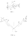
- FIG. 1 shows embodiment 1000 of the present invention.
- embodiment 1000 comprises two collimated radiation sources, infrared ("IR") emitters 100 and 110, and two radiation detectors, IR quadrant photodetectors 120 and 130, all of which are held in fixture 140.
- frame 140 is configured with viewport 150 for use by an ophthalmic instrument with which embodiment 1000 may be used in viewing a patient's eye 160.
- IR infrared
- emitters 100 and 110 and detectors 120 and 130 are configured as two IR emitter-detector pairs (pair 1 comprises off axis IR emitter 100 and diagonally opposed off-axis quadrant photodetector 130 and pair 2 comprises off axis IR emitter 110 and diagonally opposed off-axis quadrant photodetector 120).
- Embodiment 1000 also comprises electronic circuitry (not shown for clarity and ease of understanding the present invention) that: (a) drives emitters 100 and 110 in accordance with any one of a number of methods that are well known to those of ordinary skill in the art; (b) reads outputs from quadrant photodetectors 120 and 130 in accordance with any one of a number of methods that are well known to those of ordinary skill in the art; and (c) interfaces with a controller (not shown) in accordance with any one of a number of methods that are well known to those of ordinary skill in the art.
- electronic circuitry that performs these functions can also be a part of the controller, which controller can be, for example, a computer.
- a software routine that operates in a manner to be described in detail below converts outputs from detectors 120 and 130 to an X,Y,Z position of the vertex of the cornea of patient's eye 160.
- FIG. 2 shows a diagram of light paths involved in using embodiment 1000 of the present invention for emitter-detector pair 1 which comprises off axis IR emitter 100 and diagonally opposed, off-axis, quadrant photodetector 130.
- patient's eye 160 is disposed at a predetermined location with respect to fixture 150 (not shown in FIG. 2) by use of head seating fixture (not shown), which predetermined location provides placement of the cornea of the patient's eye at a nominal corneal position (all of this being done in accordance with any one of a number of methods which are well known to those of ordinary skill in the art).
- the patient may be asked to gaze at a fixation device to provide a reasonably steady choice for a nominal position.
- the fixation device may be fabricated in accordance with any one of a number of methods that are well known to those of ordinary skill in the art.
- collimated IR emitter 100 comprises source LED 101 and lens system 103
- quadrant photodetector 130 comprises lens system 131 and photodetector 133.
- lens systems 103 and 131 are configured so that IR emitter 100 and quadrant photodetector 130 have narrow fields-of-view; both of which fields of view are centered on the nominal corneal vertex position.
- radiation beam 105 emitted by LED 101 is directed to impinge upon patient's eye 160 and, after reflection thereby, is captured (as radiation beam 107) by photodetector 133.
- fixture 150 is designed in accordance with any one of a number of methods that are well known to those of ordinary skill in the art so that quadrant photodetector 130 sees an image of IR emitter 100 along a line-of-sight that passes through the nominal vertex of the cornea of patient's eye 160.
- a change in position of the vertex of the cornea of patient's eye 160 will produce a related change in the line-of-sight between the vertex of the cornea of patient's eye 160 and the quadrant photodetectors of embodiment 1000.
- output from each of quadrant photodetectors 120 and 130 enables the position of the vertex of the cornea to be measured in two dimensions.
- measurements of the line-of-sight using outputs from both quadrant photodetectors 120 and 130 are combined to measure the vertex of the cornea in three dimensions (the X,Y,Z position).
- measurement of the vertex of the cornea in three dimensions is made possible because outputs from quadrant photodetectors 120 and 130, respectively, measure lines-of-sight from two different points of reference.
- FIGs. 3A-3F illustrate the manner in which quadrant photodetectors used to fabricate embodiment 1000 of the present invention operate to indicate corneal vertex displacement of patient's eye 160.
- FIG. 3A when one of quadrant photodetectors 120 and 130 receives radiation reflected from a centered corneal vertex, radiation pattern 200 is balanced, i.e., equal illumination is received in the four quadrants of the photodetector.
- radiation pattern 210 is unbalanced, i.e., there is unequal illumination in the four quadrants of the detector.
- FIG. 3A illustrates the manner in which quadrant photodetectors used to fabricate embodiment 1000 of the present invention operate to indicate corneal vertex displacement of patient's eye 160.
- FIG. 3B shows the illumination received by quadrant photodetectors 120 and 130, respectively, for a centered corneal vertex.
- FIG. 3C shows the illumination received by quadrant photodetectors 120 and 130, respectively, for a corneal vertex with an X offset.
- FIG. 3D shows the illumination received by quadrant photodetectors 120 and 130, respectively, for a corneal vertex with an Y offset.
- FIG. 3E shows the illumination received by quadrant photodetectors 120 and 130, respectively, for a corneal vertex with an Z offset.
- quadrant photodetectors 120 and 130 are initially aligned to a nominal corneal vertex position, i.e., a position at which both quadrant photodetectors 120 and 130 exhibit a bias which is substantially zero or which differs therefrom by a predetermined amount. For example, this may be done by placing an artificial eye, for example, a glass eye, at a nominal origin (for example, 0,0,0) to align the apparatus. Then, as will described in detail below, in accordance with the present invention, horizontal and vertical biases of quadrant photodetectors 120 and 130 provide a measure of X,Y,Z displacement from the nominal corneal vertex position with high sensitivity.
- the method used to determine the position of the corneal vertex is insensitive to the radius of curvature of the cornea.
- FIG. 3F shows how regions A, B, C, and D are defined for quadrant photodetectors 120 and 130.
- H 2 (A 2 + C 2 ) - (B 2 + D 2 ) (A 2 + B 2 + C 2 + D 2 )
- V 2 (A 2 + B 2 ) - (C 2 + D 2 ) (A 2 + B 2 + C 2 + D 2 )
- the X,Y,Z coordinates of the corneal vertex are linearly related to the horizontal and vertical biases of quadrant photodetectors 120 and 130.
- X C X (H 1 + H 2 )
- Y C Y (V 1 + V 2 )
- Z C Z (H 1 - H 2 )
- C X , C Y , and C Z are constants that are determined by geometry and/or calibration in accordance with any one of a number of methods that are well known to those of ordinary skill in the art.
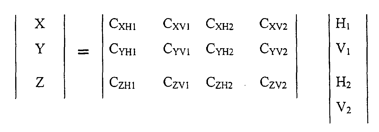
- quadrant photodetectors 120 and 130 may be oriented with an arbitrary polar orientation.
- the X,Y,Z coordinates of the corneal vertex are given by the following matrix relationship: where C XH1 , C YH1 , C ZH1 , C XV1 , C YV1 , C ZV1 , C XH2 , C YH2 , C ZH2 , C XV2 , C YV2 , and C ZV2 are constants that are determined by geometry and/or calibration in accordance with any one of a number of methods that are well known to those of ordinary skill in the art.
- cross-talk between emitter-photodetector pairs (100, 130) and (110, 120), respectively can be minimized by alternately running only one emitter-photodetector pair at a time in accordance with signals that are generated in the electronic circuitry in accordance with any one of a number of methods that are well known to those of ordinary skill in the art.
- the electronic circuitry includes synchronous detection apparatus that operates in accordance with any one of a number of methods that are well known to those of ordinary skill in the art to reject unwanted signals in the photodetectors.
- LED emitters 100 and 110 do not operate continuously, but flash in response to input from energizer portions of electronic circuitry which are fabricated in accordance with any one of a number of methods that are well known to those of ordinary skill in the art. Then, in accordance with the present invention, photodetector inputs are analyzed at times which correspond to times at which radiation reflected from the patient's eye is expected to be received, which times can be readily synchronized with the times during which the emitters are energized.
- emitters 100 and 110 are configured so that on-axis images thereof, i.e., images that are reflected from patient's eye 160 and pass through viewport 150 of frame 140 are minimized. This is done to reduce interference with ophthalmic instruments with which embodiments of the present invention are used.
- the output from embodiment 1000 which measures the X,Y,Z position data associated with the corneal vertex can be used to cause an ophthalmic instrument to make measurements whenever the vertex is sufficiently close to a predetermined position or the vertex position measurement data may be supplied to the ophthalmic instrument for use in determining or correcting diagnostic errors produced thereby.
- the output from embodiment 1000 which measures the X,Y,Z position data associated with the corneal vertex can be used to cause an motorized system to drive a servomechanism to move the corneal vertex toward a predetermined position, or to cause a feedback cue to be given to an operator to prompt corrective positioning action.
- FIG. 4 shows a block diagram of an embodiment of the present invention used in conjunction with an ophthalmic instrument.
- emitter-photodetector pairs (420, 450) and (430, 440) are affixed to frame 410 which provides a line of sight between patient's eye 400 and ophthalmic instrument 500.
- emitters 420 and 430 are connected to emitter circuitry 510, which emitter circuitry 510 operates in response to signals from controller 530 to transmit electrical pulses to energize emitters 420 in accordance with any one of a number of methods that are well known to those of ordinary skill in the art.
- FIG. 4 shows a block diagram of an embodiment of the present invention used in conjunction with an ophthalmic instrument.
- emitter-photodetector pairs (420, 450) and (430, 440) are affixed to frame 410 which provides a line of sight between patient's eye 400 and ophthalmic instrument 500.
- emitters 420 and 430 are connected to emitter circuitry 510, which
- photodetectors 440 and 450 receive radiation reflected from patient's eye 400 and transmit signals to detector circuitry 520, which detector circuitry 520 transmits detector signals to controller 530 in accordance with any one of a number of methods that are well known to those of ordinary skill in the art.
- Controller 530 analyzes the detection signals in accordance with the methods described above. Further, the synchronization of emitter output and detector signal analysis may be performed by signals sent from controller 530 to emitter circuitry 510 and detector circuitry 520. Alternatively, the synchronization may be performed within controller 530.
- controller 530 may send information to be displayed on operator console 540 in accordance with any one of a number of methods that are well known to those of ordinary skill in the art, which information indicates a corneal vertex position and which information may further indicate a position correction movement that may be used to alter the position to a predetermined position.
- controller 530 may send a signal to a positioning device (not shown) for moving the position of either patient's eye 400 or ophthalmic instrument 500 in accordance with any one of a number of methods that are well known to those of ordinary skill in the art.
- controller 530 determines that the position of the corneal vertex of patient's eye 400 is at a predetermined position
- controller 530 can sent a message in accordance with any one of a number of methods that are well known to those of ordinary skill in the art to ophthalmic instrument 500.
- ophthalmic instrument can take an appropriate action such as making a measurement of patient's eye 400.
- embodiments of the present invention were discussed in terms of using quadrant photodetectors, embodiments may be fabricated using, for example, video detectors such as for example, CCD video detectors. In such a case, the video photodetector outputs are analyzed in accordance with any one of a number of methods that are well known to those of ordinary skill in the art to determine a horizontal and vertical bias of the radiation reflected by the patient's eye.
Landscapes
- Health & Medical Sciences (AREA)
- Life Sciences & Earth Sciences (AREA)
- Physics & Mathematics (AREA)
- Engineering & Computer Science (AREA)
- Medical Informatics (AREA)
- Animal Behavior & Ethology (AREA)
- Biomedical Technology (AREA)
- Heart & Thoracic Surgery (AREA)
- Biophysics (AREA)
- Molecular Biology (AREA)
- Surgery (AREA)
- Ophthalmology & Optometry (AREA)
- General Health & Medical Sciences (AREA)
- Public Health (AREA)
- Veterinary Medicine (AREA)
- General Physics & Mathematics (AREA)
- Optics & Photonics (AREA)
- Human Computer Interaction (AREA)
- Eye Examination Apparatus (AREA)
Abstract
Description
Claims (12)
- An apparatus to determine a position of an eye which comprises:two off-axis, radiation emitter - photodetector pairs, wherein an emitter of a pair is disposed to transmit radiation toward the eye and a photodetector of the pair is disposed to receive radiation reflected by the eye; anda controller that analyzes output from the photodetectors to determine the position of the eye.
- The apparatus of claim 1 wherein the photodetectors are quadrant photodetectors.
- The apparatus of claim 2 wherein the emitters are sources of collimated radiation.
- The apparatus of claim 3 wherein the emitters comprise infrared LEDs.
- The apparatus of claim 1 wherein the photodetectors are CCD photodetectors and the controller analyzes output from the photodetectors to determine a horizontal and vertical bias of the radiation reflected by the eye.
- The apparatus of claim 5 wherein the emitters are sources of collimated infrared radiation.
- The apparatus of claim 4 wherein the emitters and the photodetectors have narrow fields-of-view that are centered on a predetermined position by a frame.
- The apparatus of claim 7 wherein X,Y,Z, coordinates of the position of the eye are linearly related to horizontal and vertical biases of the photodetector outputs.
- The apparatus of claim 8 wherein the controller causes one emitter - photodetector pair to run at a time, whereby cross-talk between the emitter - photodetector pairs is minimized.
- The apparatus of claim 8 wherein the controller synchronizes the emitter - photodetector pair operation.
- The apparatus of claim 1 wherein the controller sends a signal to an ophthalmic instrument whenever the position is substantially close to a predetermined position.
- The apparatus of claim 1 wherein the controller sends a signal to a motorized system to drive a servomechanism to move the apparatus or eye or to cause a feedback cue to be given to an operator.
Applications Claiming Priority (2)
| Application Number | Priority Date | Filing Date | Title |
|---|---|---|---|
| US502063 | 2000-02-10 | ||
| US09/502,063 US6220706B1 (en) | 2000-02-10 | 2000-02-10 | Method and apparatus for determining position of an eye |
Publications (2)
| Publication Number | Publication Date |
|---|---|
| EP1125544A2 true EP1125544A2 (en) | 2001-08-22 |
| EP1125544A3 EP1125544A3 (en) | 2003-08-13 |
Family
ID=23996171
Family Applications (1)
| Application Number | Title | Priority Date | Filing Date |
|---|---|---|---|
| EP01102961A Withdrawn EP1125544A3 (en) | 2000-02-10 | 2001-02-08 | Method and apparatus for determining position of an eye |
Country Status (2)
| Country | Link |
|---|---|
| US (1) | US6220706B1 (en) |
| EP (1) | EP1125544A3 (en) |
Cited By (3)
| Publication number | Priority date | Publication date | Assignee | Title |
|---|---|---|---|---|
| EP1308125A3 (en) * | 2001-11-06 | 2003-09-17 | Leica Microsystems Inc. | Alignment system for an ophthalmic instrument |
| DE10315262B4 (en) * | 2002-04-05 | 2010-01-21 | Reichert, Inc. | Alignment system for a hand-guided ophthalmic device |
| DE102009030466A1 (en) * | 2009-06-23 | 2011-01-05 | Carl Zeiss Meditec Ag | Method and device for aligning location-related eye data |
Families Citing this family (13)
| Publication number | Priority date | Publication date | Assignee | Title |
|---|---|---|---|---|
| US7113818B2 (en) * | 2002-04-08 | 2006-09-26 | Oti Ophthalmic Technologies Inc. | Apparatus for high resolution imaging of moving organs |
| DE10250569A1 (en) * | 2002-10-28 | 2004-05-13 | Carl Zeiss Meditec Ag | Ophthalmic device and device positioning method |
| DE10254369A1 (en) * | 2002-11-21 | 2004-06-03 | Carl Zeiss Meditec Ag | Ophthalmic device with eye tracker unit |
| US7401921B2 (en) * | 2004-05-12 | 2008-07-22 | Carl Zeiss Meditec, Inc. | Motorized patient support for eye examination or treatment |
| DE102005004642A1 (en) * | 2005-01-28 | 2006-08-10 | Carl Zeiss Meditec Ag | Patient and eye positioning arrangement for ophthalmologic diagnosis and therapy, has control system connected with navigation route and eye tracking system, and patient transport unit positionable in three directions |
| US7452077B2 (en) * | 2006-08-29 | 2008-11-18 | Carl Zeiss Meditec, Inc. | Image adjustment derived from optical imaging measurement data |
| US7621636B2 (en) * | 2007-01-10 | 2009-11-24 | Clarity Medical Systems, Inc. | Working distance and alignment sensor for a fundus camera |
| ITTV20100016A1 (en) * | 2010-02-17 | 2011-08-18 | Ct Vue S P A | IMPROVED OPHTHALMIC EQUIPMENT AND RELATIVE METHOD |
| US8885882B1 (en) | 2011-07-14 | 2014-11-11 | The Research Foundation For The State University Of New York | Real time eye tracking for human computer interaction |
| TWI480021B (en) * | 2012-04-27 | 2015-04-11 | Crystalvue Medical Corp | Assist in gaze focusing on the fundus detection device |
| TWM474479U (en) * | 2013-11-06 | 2014-03-21 | Pixart Imaging Inc | Eye tracking apparatus and image capture module thereof |
| US10016130B2 (en) | 2015-09-04 | 2018-07-10 | University Of Massachusetts | Eye tracker system and methods for detecting eye parameters |
| CN113316805A (en) * | 2019-01-17 | 2021-08-27 | 俊戈连接公司 | Method and system for monitoring a person using infrared and visible light |
Family Cites Families (27)
| Publication number | Priority date | Publication date | Assignee | Title |
|---|---|---|---|---|
| US4102564A (en) | 1975-04-18 | 1978-07-25 | Michael Henry L | Portable device for the accurate measurement of eye movements both in light and obscurity |
| US4145122A (en) | 1977-05-31 | 1979-03-20 | Colorado Seminary | Method and apparatus for monitoring the position of the eye |
| US4209252A (en) | 1978-07-03 | 1980-06-24 | Arditty Herve J | Optical probe assembly for detecting the position of an object surface and method |
| JPS565637A (en) | 1979-06-28 | 1981-01-21 | Tokyo Optical | Operation distance detector in ophthalmology machine |
| JPS5772625A (en) | 1980-09-24 | 1982-05-07 | Tokyo Optical | Ophthalmology machine equipped with apparatus for automatically detecting correct position of eye to be inspected |
| US4387974A (en) | 1981-05-11 | 1983-06-14 | The United States Of America As Represented By The Secretary Of The Navy | Circuit for calculating the position of the eye |
| US4702575A (en) | 1981-05-11 | 1987-10-27 | The United States Of America As Represented By The Secretary Of The Navy | Helmet mounted eye tracker using a position sensing detector |
| JPS59101129A (en) | 1982-11-30 | 1984-06-11 | キヤノン株式会社 | Ophthalmological instrument alignment accuracy determination device |
| SE8405802D0 (en) | 1984-11-19 | 1984-11-19 | Polish Academy Of Sciences | Eye movement measuring apparatus |
| JPS61185248A (en) | 1985-02-09 | 1986-08-18 | キヤノン株式会社 | Ophthalmological measuring device |
| US5016282A (en) * | 1988-07-14 | 1991-05-14 | Atr Communication Systems Research Laboratories | Eye tracking image pickup apparatus for separating noise from feature portions |
| US4902121A (en) | 1988-10-04 | 1990-02-20 | Allergan Humphrey | Range detector for eye instrument having interrogating beam |
| US5865832A (en) * | 1992-02-27 | 1999-02-02 | Visx, Incorporated | System for detecting, measuring and compensating for lateral movements of a target |
| JPH0315434A (en) | 1989-06-13 | 1991-01-23 | Canon Inc | Eye refractometer |
| US5333029A (en) | 1990-10-12 | 1994-07-26 | Nikon Corporation | Camera capable of detecting eye-gaze |
| JP3385055B2 (en) | 1993-01-12 | 2003-03-10 | 株式会社ニデック | Optometry device |
| JP2988178B2 (en) | 1993-03-11 | 1999-12-06 | 日産自動車株式会社 | Gaze direction measuring device |
| JP3283339B2 (en) | 1993-04-30 | 2002-05-20 | 株式会社ニデック | Ophthalmic equipment |
| US5596377A (en) | 1993-08-31 | 1997-01-21 | Nidek Co., Ltd. | Ophthalmic apparatus having three dimensional calculating means |
| US5406074A (en) | 1994-02-07 | 1995-04-11 | Grisell; Ronald D. | Noninvasive, remote eye position and orientation measurement system using light beams normal to the surface of the eye |
| US5532769A (en) | 1994-03-31 | 1996-07-02 | Nidek Co., Ltd. | Ophthalmologic alignment device with automatic alignment means |
| JP3441159B2 (en) | 1994-04-15 | 2003-08-25 | 株式会社ニデック | Ophthalmic equipment |
| JP3420342B2 (en) | 1994-06-23 | 2003-06-23 | キヤノン株式会社 | Position detection device for ophthalmic equipment |
| GB2293659B (en) | 1994-09-30 | 1998-06-24 | Nidek Kk | Ophthalmic apparatus provided with alignment mechanism |
| JP3317806B2 (en) | 1994-10-26 | 2002-08-26 | 株式会社トプコン | Ophthalmic instruments |
| JP3439546B2 (en) | 1994-10-28 | 2003-08-25 | 株式会社トプコン | Corneal shape measuring device |
| JP3533277B2 (en) | 1995-11-30 | 2004-05-31 | 株式会社ニデック | Ophthalmic equipment |
-
2000
- 2000-02-10 US US09/502,063 patent/US6220706B1/en not_active Expired - Lifetime
-
2001
- 2001-02-08 EP EP01102961A patent/EP1125544A3/en not_active Withdrawn
Cited By (3)
| Publication number | Priority date | Publication date | Assignee | Title |
|---|---|---|---|---|
| EP1308125A3 (en) * | 2001-11-06 | 2003-09-17 | Leica Microsystems Inc. | Alignment system for an ophthalmic instrument |
| DE10315262B4 (en) * | 2002-04-05 | 2010-01-21 | Reichert, Inc. | Alignment system for a hand-guided ophthalmic device |
| DE102009030466A1 (en) * | 2009-06-23 | 2011-01-05 | Carl Zeiss Meditec Ag | Method and device for aligning location-related eye data |
Also Published As
| Publication number | Publication date |
|---|---|
| EP1125544A3 (en) | 2003-08-13 |
| US6220706B1 (en) | 2001-04-24 |
Similar Documents
| Publication | Publication Date | Title |
|---|---|---|
| US6220706B1 (en) | Method and apparatus for determining position of an eye | |
| US7766479B2 (en) | View point detecting device | |
| JP5858433B2 (en) | Gaze point detection method and gaze point detection device | |
| US4287410A (en) | Double Purkinje eye tracker | |
| US7891812B2 (en) | Aberrometer provided with a visual acuity testing system | |
| US9351638B2 (en) | Hand-held ophthalmological device | |
| JP4233426B2 (en) | Eye refractive power measuring device | |
| US7413305B2 (en) | Ophthalmologic apparatus and related positioning method | |
| US5071245A (en) | Ocular refracting power measuring system | |
| CN1585619A (en) | eye wave front measurement device | |
| CN103976707A (en) | OCT (Optical Coherence Tomography) system for measuring optical path value of axis oculi and method | |
| JP3944463B2 (en) | Adjustment system for portable ophthalmic device | |
| JP3703310B2 (en) | Hand-held ophthalmic device | |
| US5502521A (en) | Ophthalmometric apparatus | |
| CN107788946A (en) | Subjective formula optometry equipment and subjective formula optometry program | |
| WO2022024104A1 (en) | Eye tracking systems and methods | |
| WO1993021820A1 (en) | Interferometer apparatus for measuring cornea velocity | |
| JPH035810B2 (en) | ||
| WO2007146714A2 (en) | Methods and apparatus for locating the eye in three demensions | |
| JPH04272743A (en) | Both eye eyeball motion measuring instrument | |
| US20040135970A1 (en) | Ophthalmic refractometer and method of operating an ophthalmic refractometer | |
| JPH0430296B2 (en) | ||
| JP2707337B2 (en) | Corneal shape measuring device | |
| CN204033314U (en) | Automatic tracking system | |
| JPS6213010B2 (en) |
Legal Events
| Date | Code | Title | Description |
|---|---|---|---|
| PUAI | Public reference made under article 153(3) epc to a published international application that has entered the european phase |
Free format text: ORIGINAL CODE: 0009012 |
|
| AK | Designated contracting states |
Kind code of ref document: A2 Designated state(s): AT BE CH CY DE DK ES FI FR GB GR IE IT LI LU MC NL PT SE TR |
|
| AX | Request for extension of the european patent |
Free format text: AL;LT;LV;MK;RO;SI |
|
| PUAL | Search report despatched |
Free format text: ORIGINAL CODE: 0009013 |
|
| AK | Designated contracting states |
Designated state(s): AT BE CH CY DE DK ES FI FR GB GR IE IT LI LU MC NL PT SE TR |
|
| AX | Request for extension of the european patent |
Extension state: AL LT LV MK RO SI |
|
| 17P | Request for examination filed |
Effective date: 20040211 |
|
| RAP1 | Party data changed (applicant data changed or rights of an application transferred) |
Owner name: CARL ZEISS STIFTUNG TRADING AS CARL ZEISS Owner name: CARL ZEISS |
|
| AKX | Designation fees paid |
Designated state(s): AT BE CH CY DE DK ES FI FR GB GR IE IT LI LU MC NL PT SE TR |
|
| 17Q | First examination report despatched |
Effective date: 20040326 |
|
| RAP1 | Party data changed (applicant data changed or rights of an application transferred) |
Owner name: CARL-ZEISS-STIFTUNG TRADING AS CARL ZEISS Owner name: CARL ZEISS |
|
| STAA | Information on the status of an ep patent application or granted ep patent |
Free format text: STATUS: THE APPLICATION IS DEEMED TO BE WITHDRAWN |
|
| 18D | Application deemed to be withdrawn |
Effective date: 20040806 |