EP1125293B1 - Method of and device for recording information - Google Patents
Method of and device for recording information Download PDFInfo
- Publication number
- EP1125293B1 EP1125293B1 EP00951375A EP00951375A EP1125293B1 EP 1125293 B1 EP1125293 B1 EP 1125293B1 EP 00951375 A EP00951375 A EP 00951375A EP 00951375 A EP00951375 A EP 00951375A EP 1125293 B1 EP1125293 B1 EP 1125293B1
- Authority
- EP
- European Patent Office
- Prior art keywords
- recording
- area
- replacement
- disc
- user area
- Prior art date
- Legal status (The legal status is an assumption and is not a legal conclusion. Google has not performed a legal analysis and makes no representation as to the accuracy of the status listed.)
- Expired - Lifetime
Links
Images
Classifications
-
- G—PHYSICS
- G11—INFORMATION STORAGE
- G11B—INFORMATION STORAGE BASED ON RELATIVE MOVEMENT BETWEEN RECORD CARRIER AND TRANSDUCER
- G11B20/00—Signal processing not specific to the method of recording or reproducing; Circuits therefor
- G11B20/10—Digital recording or reproducing
- G11B20/18—Error detection or correction; Testing, e.g. of drop-outs
- G11B20/1883—Methods for assignment of alternate areas for defective areas
-
- G—PHYSICS
- G11—INFORMATION STORAGE
- G11B—INFORMATION STORAGE BASED ON RELATIVE MOVEMENT BETWEEN RECORD CARRIER AND TRANSDUCER
- G11B7/00—Recording or reproducing by optical means, e.g. recording using a thermal beam of optical radiation by modifying optical properties or the physical structure, reproducing using an optical beam at lower power by sensing optical properties; Record carriers therefor
- G11B7/007—Arrangement of the information on the record carrier, e.g. form of tracks, actual track shape, e.g. wobbled, or cross-section, e.g. v-shaped; Sequential information structures, e.g. sectoring or header formats within a track
- G11B7/0079—Zoned data area, e.g. having different data structures or formats for the user data within data layer, Zone Constant Linear Velocity [ZCLV], Zone Constant Angular Velocity [ZCAV], carriers with RAM and ROM areas
-
- G—PHYSICS
- G11—INFORMATION STORAGE
- G11B—INFORMATION STORAGE BASED ON RELATIVE MOVEMENT BETWEEN RECORD CARRIER AND TRANSDUCER
- G11B20/00—Signal processing not specific to the method of recording or reproducing; Circuits therefor
- G11B20/10—Digital recording or reproducing
- G11B2020/10935—Digital recording or reproducing wherein a time constraint must be met
- G11B2020/10944—Real-time recording or reproducing, e.g. for ensuring seamless playback of AV data
-
- G—PHYSICS
- G11—INFORMATION STORAGE
- G11B—INFORMATION STORAGE BASED ON RELATIVE MOVEMENT BETWEEN RECORD CARRIER AND TRANSDUCER
- G11B2220/00—Record carriers by type
- G11B2220/20—Disc-shaped record carriers
-
- G—PHYSICS
- G11—INFORMATION STORAGE
- G11B—INFORMATION STORAGE BASED ON RELATIVE MOVEMENT BETWEEN RECORD CARRIER AND TRANSDUCER
- G11B2220/00—Record carriers by type
- G11B2220/20—Disc-shaped record carriers
- G11B2220/25—Disc-shaped record carriers characterised in that the disc is based on a specific recording technology
- G11B2220/2537—Optical discs
Definitions
- the present invention generally relates to the recording of information, particularly digital information, on a disc-shaped recording medium such as an optical disc or a magnetic disc, hereinafter also referred to as "recording disc ".
- a recording disc has a multitude of concentric substantially circular recording tracks.
- Such recording tracks may take the form of individual circular tracks or of one continuous spiral track.
- Each track is divided into logic blocks and each block has a data area for the recording of data.
- each block usually has an area reserved for the recording of a check number or "check sum".
- the amount of information to be recorded in a recording session is greater than one block.
- the information to be recorded also referred as "file”
- file is then divided into successive data packets having the size of one block, and the successive data packets of a file are recorded in different blocks of the disc.
- the successive data packets are recorded in successive blocks.
- the recording process can then proceed virtually continuously.
- the subsequent reading (playback) of the information recorded on the disc the read process can proceed continuously.
- a disc may exhibit defective blocks, i.e. blocks where a faultless recording of information is no longer possible or where any resulting small write errors can no longer be corrected during reading. Such a block is then no longer suited for recording. It is customary to reserve a spare area on the recording disc, which area cannot be addressed by the user and is intended for replacement of any defective blocks. When during recording a defective block is found, recording is effected in a block of the spare recording area instead of in the defective block.
- EP 0569045 A1 discloses an information recording medium such as an optical disk comprising a first substitute region for replacing an initial defective region, the first substitute region being adjacent to the initial defective region, and a second substitute region for replacing a later defective region which occurs after an occurrence of the initial defective region. Also a recording and reproducing apparatus comprising means for detecting a defective region in an information recording medium; and means for setting first and second substitute regions in the information recording medium in response to the detecting of the defective region, the first and second substitute regions replacing initial and later defective regions respectively, the initial defective region being adjacent to the initial defective region and the later defective region arising after the occurrence of the initial defective region.
- EP 0 798 710 discloses an information recording disk having a replacement area that can be arranged at any portion in the zone where the rotation speed is equal to that of the data area. A replacement area is formed for each constant rotation speed zone.
- WO 0031737 discloses a method of assigning a spare area of an optical recording medium having a data area comprising: a first mode in which both a primary spare area and a supplementary spare area are assigned; a second mode in which a primary spare area is assigned; and assigning the spare area according to one of either the first mode or the second mode when the optical recording medium is formatted.
- EP 1 014 365 discloses a recording medium characterized in that a primary spare area allocated upon initialization and a supplementary spare area allocated after initialization are provided, and the sizes of the spare areas are determined by the number of defects generated upon initialization.
- the replacement recording is effected in a free recording area, i.e. a freely accessible addressable area which has not yet been used.
- This area is large enough to record file portions having a length of hundreds of blocks in succession.
- the allocation manager reserves a certain portion of the free recording area as a replacement area. This reservation implies, on the one hand, that the allocation manager will not use the addresses in this reserved portion of the free recording area for recording. If during recording a defective block is found the write head jumps to a suitable address in the reserved replacement zone of the free recording area, for example the first free address in the replacement zone, and a replacement recording is made in said replacement zone. After recording of a file portion in this replacement zone the write head returns to the normal recording area.
- the allocation manager Upon completion of the recording session the allocation manager is informed which addresses in the replacement zone have been used for replacement and which replacement addresses correspond to which original addresses. The allocation manager then knows which addresses of the free area are no longer free and which of the originally allocated addresses have not been used and are therefore, in fact, still free.
- this information may already be transferred to the allocation manager during the recording session, as a result of which, if this is necessary, the allocation manager can reserve additional space in the normally accessible space during the recording process, for example when a very large number of errors occurs.
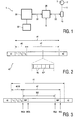
- Fig. 1 shows a block diagram of a part of a recording apparatus 1 suitable for recording real-time video or audio signals S on a recording disc 2.
- the disc 2 may be a magnetic disc but the present invention is intended particularly for optical recording.
- the disc 2 has a multitude of mutually concentric recording tracks 3, which are assumed to be individual circular tracks hereinafter but it is likewise possible that the tracks 3 represent one continuous spiral track.
- the apparatus 1 has an optical write/read head 10 and a turntable, which is not shown for the sake of simplicity and which faces the head 10, on which turntable the disc 2 can be positioned and by means of which the disc 2 can be given a rotational movement with respect to the head 10, thus enabling a track 3 to be scanned by the head 10.
- the recording apparatus 1 further includes means, which are known per se and which are not shown for the sake of simplicity, for moving the head 10 in a radial direction of the disc 2, thus enabling different tracks 3 of the disc 2 to be accessed by the head 10. As is well-known, information is written in the track 3 by means of a laser beam 11 from the head 10.
- the write process is controlled by a functional unit 20, referred to hereinafter as the write control unit.
- a write control unit 20 is known per se and is therefore not described any further. It is to be noted merely that the write control unit 20 is adapted to control the positioning of the head 10 with respect to the disc 2 in such a manner that the write process takes place at a desired location on the disc 2 through control of said turntable for the disc 2 and said positioning means for the write head 10. Furthermore, the write control unit 20 control the intensity of the laser beam 11 in dependence on the input signal S to be recorded. This control function of the write control unit 20 is represented diagrammatically as the coupling 22 in Fig. 1 .
- the recording apparatus 1 further has a functional unit 30, hereinafter termed the allocation manager.
- the allocation manager 30 is know per se and is therefore not described any further. It is to be noted merely that the allocation manager 30 is adapted to determine on which part of the disc 2 a certain recording session or recording is to take place. When a user starts a recording the allocation manager 30 determines whether there is enough space for the recording on the relevant disc 2, and if this is the case, where this space is available. The allocation manager 30 informs the write control unit 20 of the starting location of this available space, which is represented diagrammatically as the signal coupling 31.
- Fig. 2 diagrammatically represents the logic structure of the disc 2.
- the recording tracks 3 together define a recordable area 40 of the disc 2, which is shown as a continuous strip and which will also be referred to hereinafter as the recording area.
- the recording area 40 of the disc 2 has been divided into logic blocks 45, which each have an individual predetermined address.
- the value of the relevant address of a block 45 has been recorded in a predetermined address field of the block 45. It is thus possible to record information directly at a given location which corresponds to a given address on the disc 2 and it is likewise possible to read the information directly from a given location which corresponds to a given address.
- the blocks 45 have a block size which needs not be equal for all the blocks.
- the amount of data that can be written in one block is termed a data packet.
- the recording area 40 of the disc 2 further includes a spare area 42, which is not addressable and which is used as a replacement area.
- the relative storage capacities of the user area 41 and the spare area 42 are not shown to scale in Fig. 2 : in general, the size of the spare area 42 is only a few per cent of the size of the user area 41.
- the disc 2 further has a predetermined area 43 which stores information relating to the contents of the disc. This information may relate to, for example, the number of files on the disc 2, the start addresses of the files, the lengths of the files, the names of the files etc.
- This area 43 will also be referred to hereinafter as the administrative area.
- files bear the references f1, f2, f3 etc.
- files occupy a plurality of blocks 45, so that a file comprises a plurality of data packets.
- the part of the user area 41 which has already been used for file storage will be referred to as occupied user area 46 or occupied space.
- the non-used part of the user area 41 is still free: this part will be referred to hereinafter as the free user area or free space 47.
- the blocks which are used by a file do not necessarily adjoin one another directly in the addressable area 41.
- the file may comprise a plurality of segments, which may each comprise a plurality of blocks, which segments may be scattered within the addressable area 41.
- the free space therefore consists of a plurality of segments with blocks that have not yet been used. These addresses are kept in the administrative space 43.
- the files are represented as a single continuous area.
- the allocation manager 30 instructs the write control unit 20, via the coupling 31, to read the administrative area 43 and to transfer the information thus read to the allocation manager 30 via the coupling 31.
- the allocation manager 30 stores the read information in an associated memory 32.
- the allocation manager 30 now knows which part of the user area 41 of the disc 2 is occupied by prior recordings of files f1, f2 etc. and is consequently occupied user area 46 or occupied space. As a consequence, the allocation manager 30 also knows which part of the user area 41 is still free and is consequently free user area or free space 47.
- the allocation manager 30 When the allocation manager 30 receives a new write command the allocation manager 30 checks in the associated memory 32 which part of the user area 41 is free space and sends a start address and an end address in this free space to the write control unit 20 via the communication line 31. The allocation manager 30 also stores this data in the memory 32 as an indication that the portion of the user area 41 defined by said start address and end address no longer belongs to the free user area 47 but to the occupied user area 46.
- the write control unit 20 controls the recording process for the incoming signal S to be recorded, which is effected in a customary manner, starting at said start address received from the allocation manager 30. When the recording process has been completed the write control unit 20 reports this to the allocation manager 30 via the communication line 31, after which the allocation manager 30 instructs the write control unit 20 to update the data in the administrative area 43 of the disc 2.
- the user area 41 may contain defective blocks 45*. It is then possible that the presence of certain defective blocks 45* is not known in advance to the allocation manager 30, as a result of which, these defective blocks 45* are normally used for allocation. However, it is also possible that prior to recording the allocation manager 30 knows which blocks are unusable as a result of the presence of defects. In the conventional manner these blocks 45* are still used for allocation.
- the write control unit 20 is assumed to select an alternative location by itself. If during the write process the write head 10 then reaches a defective block 45*, the write control unit 20 should move the write head 10 to an alternative block and the data packet which should have been written in the relevant defective block 45* is recorded in said alternative block. After recording of the data packet in the alternative block the write control unit 20 directs the write head 10 back to the user area 41 in the conventional manner.
- Such an alternative block is also termed a replacement block 45' and the recording of the data packet in a replacement block 45' is also referred to as a replacement recording.
- an alternative block 45' is selected in the spare area 42.
- the present invention proposes to reduce the number of jump movements of write head 10 and to increase the time between successive jump movements in that, when the write head 10 reaches a defective block 45* and it is consequently necessary to jump to a replacement block 45', the replacement recording is effected not just for the single data packet to be written into the defective block but in that prior to jumping back also a large number of subsequent data packets are written into the replacement blocks 45*.
- the number of subsequent data packets thus written into the replacement blocks 45' can be 100 or more. As a matter of fact, errors often occur in clusters. By taking a larger number of data packets the number of jumps is reduced.
- Such a sequence of successive data packets written into replacement blocks 45' is also termed a file portion.
- the predefined reserve area 42 is comparatively small.
- this spare area 42 has been designed for a capacity of approximately 3 % of the overall disc capacity, thus providing an alternative write capability for all the defective blocks 45* if not more than 3 % of the blocks are defective. In the conventional write process this is amply sufficient in practice because in that case only a single replacement block 45' in the spare area 42 is utilized for each defective block 45* in the user area 41.
- file portions having a size of 100 or more data packets are written in the spare area 42 at the same time, it is inevitable that also a large number of replacement blocks 45' of the spare area 42 are required as an alternative recording area for non-defective blocks 45 of the user area 41.
- This means that the spare area 42 is filled rapidly and may already be full even when the number of defective blocks 45* in the user area 41 is much smaller than 3 %. When the spare area 42 is full the disc 2 can no longer be used for further recording.
- the present invention also provides a solution for this problem.
- the allocation manager 30 is adapted to reserve two different areas in the free user area for recording, a first area being reserved for normal recording and a second area being reserved for replacement recording.
- the allocation manager 30 informs the write control unit 20 about these areas.
- the write control unit 20 is adapted to perform a normal recording in the first area and, when defective blocks 45* are found, to perform a replacement recording for a file portion in the second area.
- the allocation manager 30 can, for this purpose, be adapted to specify a write start address WSA and a write end address WEA in the free user area 47, which addresses reserve an area NW for normal recording, and to specify also a replacement start address RSA and a replacement end address REA in the free user area 47, which addresses reserve an area RW for replacement recording.
- Fig. 3 shows that the area NW reserved for normal recording is situated at the beginning of the free user area 47 and the area RW reserved for replacement recording is situated at the end of the free user area 47.
- the free user area will comprise a plurality of non-adjoining areas scattered over the entire addressable space. Therefore, it is also possible that the area RW reserved for replacement recording adjoins the area NW reserved for normal recording.
- the allocation manager 30 is adapted to communicate these addresses to the write control unit 20, which in its turn is adapted to ensure that the recording of the information stream in the area NW reserved for normal recording within the free user area 47 proceeds in the conventional manner.
- the write control unit 20 is adapted to ensure that, when a defective sector 45* is found, the write head 10 jumps to a location in the replacement zone RW within the free user are 47, to effect a replacement recording of a file portion at said location, and subsequently to cause the write head 10 to jump back to the area NW reserved for normal recording within the free user area 47. It will be evident that in this way replacement recording is effected without the drawbacks described hereinbefore. Thus, in particular, the spare area 42 is not utilized.
- the write control unit 20 reports to the allocation manager 30 when the recording process has finished, upon which the allocation manager 30 instructs the write control unit 20 to update the data in the administrative area 43 of the disc 2.
- the allocation manager 30 adds the addresses in the area RW reserved for replacement recording to said administrative data in the administrative area 43.
- the non-used addresses with the defects are left in the free user area. It is possible to add these addresses to the list of non-reliable addresses. During a subsequent recording the allocation manager 30 could then decide not to use these addresses for allocation. This precludes a loss of time during re-allocation.
- the occupied space 46 of the user area 41 now comprises a part 46W occupied by normal recording, the blocks already used in the area NW, and the blocks already used in the area RW.
- the allocation manager 30 writes this into the memory 32 and, upon completion of the recording session, it records the information in the table of contents in the administrative area 43 on the disc.
- the allocation manager 30 recognizes the addresses that have been used. From this information it can derive what free user area is left. A part of this area is reserved for replacement recording. This need not be the same part as during a previous recording.
- the size of the replacement zone RW in the free user area 47 is larger than that of the spare area 42 and large enough to handle the number of replacement recordings which occurs under normal conditions.
- the allocation manager 30 can reduce the replacement space by informing the write control unit 20 of this. In this way, the whole disc can be used for storage. It is possible that during the recording session the write control unit 20 also supplies information to the allocation manager 30 about the size of the residual non-used part of the replacement zone RW, as a result of which, if the number of replacement recordings is comparatively large and the replacement zone is therefore about to become full even before the recording session has been completed, the allocation manager 30 can extend the replacement zone RW.
- the method proposed by the present invention has some major advantages.
- the size of the replacement area in the free space can be changed dynamically. This does not give rise to any loss of playing time as a result of the reserved replacement area.
- the disc can still be used, even when more than 3 % of the recording area is defective. Theoretically, the disc can even be used when nearly 100 % of the storage space is defective but the residual playing time decreases according as more storage space is defective and more replacement space is required (graceful degradation). This is in contradistinction to the conventional method, where a disc is no longer usable when more than 3 % of defects occurs.
- the present invention in particular provides a method of recording real time video signals on a DVR disc having a recording area 40 which includes an administrative area 43, a spare area 42, and a user area 41.
- Normal recording is effected in blocks 45 in a first pre-reserved zone NW of a free part 47 of the user area. If a defective block 45* is encountered during the recording process a replacement recording of a file portion having the size of a plurality of blocks is made in a second pre-reserved zone RW of the free part 47 of the user area, after which normal recording is continued in the first pre-reserved zone NW.
- this reduces the number of jumps and limits the number of jumps occurring within a short period of time for the purpose of replacement recording and, on the other hand, a very efficient use is made of the storage capacity of the disc.
Abstract
Description
- The present invention generally relates to the recording of information, particularly digital information, on a disc-shaped recording medium such as an optical disc or a magnetic disc, hereinafter also referred to as "recording disc ". As is well-known, such a recording disc has a multitude of concentric substantially circular recording tracks. Such recording tracks may take the form of individual circular tracks or of one continuous spiral track. Each track is divided into logic blocks and each block has a data area for the recording of data. Furthermore, each block usually has an area reserved for the recording of a check number or "check sum".
- In general, the amount of information to be recorded in a recording session is greater than one block. The information to be recorded, also referred as "file", is then divided into successive data packets having the size of one block, and the successive data packets of a file are recorded in different blocks of the disc. For a rapid data transfer it is then desirable that the successive data packets are recorded in successive blocks. The recording process can then proceed virtually continuously. Likewise, during the subsequent reading (playback) of the information recorded on the disc the read process can proceed continuously.
- In practice, a disc may exhibit defective blocks, i.e. blocks where a faultless recording of information is no longer possible or where any resulting small write errors can no longer be corrected during reading. Such a block is then no longer suited for recording. It is customary to reserve a spare area on the recording disc, which area cannot be addressed by the user and is intended for replacement of any defective blocks. When during recording a defective block is found, recording is effected in a block of the spare recording area instead of in the defective block.
- After recording of a data packet in a block of the spare recording area the recording of the following data packets is continued in a block following the defective block. Therefore, such a replacement requires two jumps of the recording head and likewise two jumps of the read head are required to read the information.
- These jumps of the read or write head from the normal recording area to the spare recording area and back take comparatively much time and reduce the average transmission speed of the information. This is particularly undesirable in situations in which a very high transmission speed is required, as for example in a real time recording of audio and/or video signals.
- For such uses it is proposed not to make the jumps to spare recording area and back for each individual damaged block but, when a defective block is found, to record a file portion comprising a plurality of blocks in the spare area. The jumps now do not occur directly after one another in time but the time between them is longer. The transmission speed averaged over a time interval which does not include both jumps is then higher. However, a consequence is then that the spare recording area is filled rapidly, a substantial number of the data packets recorded in the spare recording area then wrongfully occupying space in the spare recording area because the blocks corresponding to these data packets in the normal recording area are not defective. Thus, a reduction of the number of jumps is attended by a comparatively inefficient use of the spare recording area and the spare recording area is filled more rapidly; once the spare recording area is full the disc can no longer be used for further recording. Conversely, this means that the number of file portions for which a replacement recording is made in the spare area is comparatively small.
-
EP 0569045 A1 discloses an information recording medium such as an optical disk comprising a first substitute region for replacing an initial defective region, the first substitute region being adjacent to the initial defective region, and a second substitute region for replacing a later defective region which occurs after an occurrence of the initial defective region. Also a recording and reproducing apparatus comprising means for detecting a defective region in an information recording medium; and means for setting first and second substitute regions in the information recording medium in response to the detecting of the defective region, the first and second substitute regions replacing initial and later defective regions respectively, the initial defective region being adjacent to the initial defective region and the later defective region arising after the occurrence of the initial defective region. -
EP 0 798 710 discloses an information recording disk having a replacement area that can be arranged at any portion in the zone where the rotation speed is equal to that of the data area. A replacement area is formed for each constant rotation speed zone. -
WO 0031737 -
EP 1 014 365 - It is an object of the present invention to provide a solution for the aforementioned problems. The invention is defined by the independent claims.
- In accordance with an important aspect of the present invention the replacement recording is effected in a free recording area, i.e. a freely accessible addressable area which has not yet been used. This area is large enough to record file portions having a length of hundreds of blocks in succession. Prior to the recording the allocation manager reserves a certain portion of the free recording area as a replacement area. This reservation implies, on the one hand, that the allocation manager will not use the addresses in this reserved portion of the free recording area for recording. If during recording a defective block is found the write head jumps to a suitable address in the reserved replacement zone of the free recording area, for example the first free address in the replacement zone, and a replacement recording is made in said replacement zone. After recording of a file portion in this replacement zone the write head returns to the normal recording area.
- Upon completion of the recording session the allocation manager is informed which addresses in the replacement zone have been used for replacement and which replacement addresses correspond to which original addresses. The allocation manager then knows which addresses of the free area are no longer free and which of the originally allocated addresses have not been used and are therefore, in fact, still free.
- At option, this information may already be transferred to the allocation manager during the recording session, as a result of which, if this is necessary, the allocation manager can reserve additional space in the normally accessible space during the recording process, for example when a very large number of errors occurs.
- It is noted that the earlier European
patent application EP 1 014 365 A2 published on 28-06-2000 (thereby forming prior art according to Article 54(3) EPC for the Contracting States DE, FR, GB and NL) describes a recording disc having a primary spare area and a supplementary spare area located in the logical file area which is allocated for linear replacement of defects while the disc is being used (i.e., after initialization of the disc). - These and other aspects, features and advantages of the present invention will be elucidated further by means of the following description of a preferred embodiment of the invention with reference to the drawings, in which:
-
Fig. 1 is a block diagram which shows a part of a recording apparatus; -
Fig. 2 diagrammatically shows the logic structure of a recording disc in order to illustrate a conventional recording method; and -
Fig. 3 diagrammatically shows the logic structure of a recording disc in order to illustrate a recording method in accordance with the present invention. -
Fig. 1 shows a block diagram of a part of arecording apparatus 1 suitable for recording real-time video or audio signals S on arecording disc 2. - The
disc 2 may be a magnetic disc but the present invention is intended particularly for optical recording. Thedisc 2 has a multitude of mutuallyconcentric recording tracks 3, which are assumed to be individual circular tracks hereinafter but it is likewise possible that thetracks 3 represent one continuous spiral track. As is known per se, theapparatus 1 has an optical write/readhead 10 and a turntable, which is not shown for the sake of simplicity and which faces thehead 10, on which turntable thedisc 2 can be positioned and by means of which thedisc 2 can be given a rotational movement with respect to thehead 10, thus enabling atrack 3 to be scanned by thehead 10. Therecording apparatus 1 further includes means, which are known per se and which are not shown for the sake of simplicity, for moving thehead 10 in a radial direction of thedisc 2, thus enablingdifferent tracks 3 of thedisc 2 to be accessed by thehead 10. As is well-known, information is written in thetrack 3 by means of alaser beam 11 from thehead 10. - The write process is controlled by a
functional unit 20, referred to hereinafter as the write control unit. Such awrite control unit 20 is known per se and is therefore not described any further. It is to be noted merely that thewrite control unit 20 is adapted to control the positioning of thehead 10 with respect to thedisc 2 in such a manner that the write process takes place at a desired location on thedisc 2 through control of said turntable for thedisc 2 and said positioning means for thewrite head 10. Furthermore, thewrite control unit 20 control the intensity of thelaser beam 11 in dependence on the input signal S to be recorded. This control function of thewrite control unit 20 is represented diagrammatically as thecoupling 22 inFig. 1 . - The
recording apparatus 1 further has afunctional unit 30, hereinafter termed the allocation manager. Such anallocation manager 30 is know per se and is therefore not described any further. It is to be noted merely that theallocation manager 30 is adapted to determine on which part of the disc 2 a certain recording session or recording is to take place. When a user starts a recording theallocation manager 30 determines whether there is enough space for the recording on therelevant disc 2, and if this is the case, where this space is available. Theallocation manager 30 informs thewrite control unit 20 of the starting location of this available space, which is represented diagrammatically as thesignal coupling 31. -
Fig. 2 diagrammatically represents the logic structure of thedisc 2. Therecording tracks 3 together define arecordable area 40 of thedisc 2, which is shown as a continuous strip and which will also be referred to hereinafter as the recording area. - The
recording area 40 of thedisc 2 has been divided intologic blocks 45, which each have an individual predetermined address. The value of the relevant address of ablock 45 has been recorded in a predetermined address field of theblock 45. It is thus possible to record information directly at a given location which corresponds to a given address on thedisc 2 and it is likewise possible to read the information directly from a given location which corresponds to a given address. Theblocks 45 have a block size which needs not be equal for all the blocks. The amount of data that can be written in one block is termed a data packet. - The
recording area 40 consists for a substantial part of a so-calledaddressable space 41, which can be accessed by a user in order to record information, in the present example digitized video signals. Thisaddressable space 41 will therefore also be referred to hereinafter as the user area. - The
recording area 40 of thedisc 2 further includes aspare area 42, which is not addressable and which is used as a replacement area. The relative storage capacities of theuser area 41 and thespare area 42 are not shown to scale inFig. 2 : in general, the size of thespare area 42 is only a few per cent of the size of theuser area 41. - The
disc 2 further has a predeterminedarea 43 which stores information relating to the contents of the disc. This information may relate to, for example, the number of files on thedisc 2, the start addresses of the files, the lengths of the files, the names of the files etc. Thisarea 43 will also be referred to hereinafter as the administrative area. - In
Fig. 2 files bear the references f1, f2, f3 etc. In general, files occupy a plurality ofblocks 45, so that a file comprises a plurality of data packets. The part of theuser area 41 which has already been used for file storage will be referred to as occupieduser area 46 or occupied space. The non-used part of theuser area 41 is still free: this part will be referred to hereinafter as the free user area orfree space 47. The blocks which are used by a file do not necessarily adjoin one another directly in theaddressable area 41. The file may comprise a plurality of segments, which may each comprise a plurality of blocks, which segments may be scattered within theaddressable area 41. The free space therefore consists of a plurality of segments with blocks that have not yet been used. These addresses are kept in theadministrative space 43. For the sake of simplicity the files are represented as a single continuous area. - When the
disc 2 is loaded into recording apparatus theallocation manager 30 instructs thewrite control unit 20, via thecoupling 31, to read theadministrative area 43 and to transfer the information thus read to theallocation manager 30 via thecoupling 31. Theallocation manager 30 stores the read information in an associatedmemory 32. Theallocation manager 30 now knows which part of theuser area 41 of thedisc 2 is occupied by prior recordings of files f1, f2 etc. and is consequently occupieduser area 46 or occupied space. As a consequence, theallocation manager 30 also knows which part of theuser area 41 is still free and is consequently free user area orfree space 47. - When the
allocation manager 30 receives a new write command theallocation manager 30 checks in the associatedmemory 32 which part of theuser area 41 is free space and sends a start address and an end address in this free space to thewrite control unit 20 via thecommunication line 31. Theallocation manager 30 also stores this data in thememory 32 as an indication that the portion of theuser area 41 defined by said start address and end address no longer belongs to thefree user area 47 but to the occupieduser area 46. Thewrite control unit 20 controls the recording process for the incoming signal S to be recorded, which is effected in a customary manner, starting at said start address received from theallocation manager 30. When the recording process has been completed thewrite control unit 20 reports this to theallocation manager 30 via thecommunication line 31, after which theallocation manager 30 instructs thewrite control unit 20 to update the data in theadministrative area 43 of thedisc 2. - The
user area 41 may containdefective blocks 45*. It is then possible that the presence of certaindefective blocks 45* is not known in advance to theallocation manager 30, as a result of which, thesedefective blocks 45* are normally used for allocation. However, it is also possible that prior to recording theallocation manager 30 knows which blocks are unusable as a result of the presence of defects. In the conventional manner theseblocks 45* are still used for allocation. Thewrite control unit 20 is assumed to select an alternative location by itself. If during the write process thewrite head 10 then reaches adefective block 45*, thewrite control unit 20 should move thewrite head 10 to an alternative block and the data packet which should have been written in the relevantdefective block 45* is recorded in said alternative block. After recording of the data packet in the alternative block thewrite control unit 20 directs thewrite head 10 back to theuser area 41 in the conventional manner. - Such an alternative block is also termed a replacement block 45' and the recording of the data packet in a replacement block 45' is also referred to as a replacement recording.
- Conventionally, an alternative block 45' is selected in the
spare area 42. - Owing to the to and fro movement of the
write head 10 much time is lost, as a result of which such a conventional write process is not very suitable for the processing of real time video signals. The present invention proposes to reduce the number of jump movements ofwrite head 10 and to increase the time between successive jump movements in that, when thewrite head 10 reaches adefective block 45* and it is consequently necessary to jump to a replacement block 45', the replacement recording is effected not just for the single data packet to be written into the defective block but in that prior to jumping back also a large number of subsequent data packets are written into the replacement blocks 45*. The number of subsequent data packets thus written into the replacement blocks 45' can be 100 or more. As a matter of fact, errors often occur in clusters. By taking a larger number of data packets the number of jumps is reduced. Such a sequence of successive data packets written into replacement blocks 45' is also termed a file portion. - The
predefined reserve area 42 is comparatively small. In particular, thisspare area 42 has been designed for a capacity of approximately 3 % of the overall disc capacity, thus providing an alternative write capability for all thedefective blocks 45* if not more than 3 % of the blocks are defective. In the conventional write process this is amply sufficient in practice because in that case only a single replacement block 45' in thespare area 42 is utilized for eachdefective block 45* in theuser area 41. However, if file portions having a size of 100 or more data packets are written in thespare area 42 at the same time, it is inevitable that also a large number of replacement blocks 45' of thespare area 42 are required as an alternative recording area fornon-defective blocks 45 of theuser area 41. This means that thespare area 42 is filled rapidly and may already be full even when the number ofdefective blocks 45* in theuser area 41 is much smaller than 3 %. When thespare area 42 is full thedisc 2 can no longer be used for further recording. - The present invention also provides a solution for this problem.
- For this purpose, in accordance with the present invention, the
allocation manager 30 is adapted to reserve two different areas in the free user area for recording, a first area being reserved for normal recording and a second area being reserved for replacement recording. Theallocation manager 30 informs thewrite control unit 20 about these areas. Thewrite control unit 20 is adapted to perform a normal recording in the first area and, whendefective blocks 45* are found, to perform a replacement recording for a file portion in the second area. - As illustrated in
Fig. 3 , theallocation manager 30 can, for this purpose, be adapted to specify a write start address WSA and a write end address WEA in thefree user area 47, which addresses reserve an area NW for normal recording, and to specify also a replacement start address RSA and a replacement end address REA in thefree user area 47, which addresses reserve an area RW for replacement recording.Fig. 3 shows that the area NW reserved for normal recording is situated at the beginning of thefree user area 47 and the area RW reserved for replacement recording is situated at the end of thefree user area 47. In reality, the free user area will comprise a plurality of non-adjoining areas scattered over the entire addressable space. Therefore, it is also possible that the area RW reserved for replacement recording adjoins the area NW reserved for normal recording. - The
allocation manager 30 is adapted to communicate these addresses to thewrite control unit 20, which in its turn is adapted to ensure that the recording of the information stream in the area NW reserved for normal recording within thefree user area 47 proceeds in the conventional manner. However, thewrite control unit 20 is adapted to ensure that, when adefective sector 45* is found, thewrite head 10 jumps to a location in the replacement zone RW within the free user are 47, to effect a replacement recording of a file portion at said location, and subsequently to cause thewrite head 10 to jump back to the area NW reserved for normal recording within thefree user area 47. It will be evident that in this way replacement recording is effected without the drawbacks described hereinbefore. Thus, in particular, thespare area 42 is not utilized. - As is customary, the
write control unit 20 reports to theallocation manager 30 when the recording process has finished, upon which theallocation manager 30 instructs thewrite control unit 20 to update the data in theadministrative area 43 of thedisc 2. Theallocation manager 30 adds the addresses in the area RW reserved for replacement recording to said administrative data in theadministrative area 43. The non-used addresses with the defects are left in the free user area. It is possible to add these addresses to the list of non-reliable addresses. During a subsequent recording theallocation manager 30 could then decide not to use these addresses for allocation. This precludes a loss of time during re-allocation. - Thus, the occupied
space 46 of theuser area 41 now comprises a part 46W occupied by normal recording, the blocks already used in the area NW, and the blocks already used in the area RW. Theallocation manager 30 writes this into thememory 32 and, upon completion of the recording session, it records the information in the table of contents in theadministrative area 43 on the disc. - When the
disc 2 is loaded into the apparatus 1 a next time a similar procedure is carried out: theallocation manager 30 recognizes the addresses that have been used. From this information it can derive what free user area is left. A part of this area is reserved for replacement recording. This need not be the same part as during a previous recording. - Normally, the size of the replacement zone RW in the
free user area 47 is larger than that of thespare area 42 and large enough to handle the number of replacement recordings which occurs under normal conditions. - If during recording the residual free user space becomes small because the disc is getting full, while there is still room in the replacement space, the
allocation manager 30 can reduce the replacement space by informing thewrite control unit 20 of this. In this way, the whole disc can be used for storage. It is possible that during the recording session thewrite control unit 20 also supplies information to theallocation manager 30 about the size of the residual non-used part of the replacement zone RW, as a result of which, if the number of replacement recordings is comparatively large and the replacement zone is therefore about to become full even before the recording session has been completed, theallocation manager 30 can extend the replacement zone RW. - Once a part of the
free user area 47 has been reserved by theallocation manager 30 theallocation manager 30 will no longer consider this part as being freely available for normal recording. - The method proposed by the present invention has some major advantages. During the recording session or recording process the size of the replacement area in the free space can be changed dynamically. This does not give rise to any loss of playing time as a result of the reserved replacement area. Moreover, the disc can still be used, even when more than 3 % of the recording area is defective. Theoretically, the disc can even be used when nearly 100 % of the storage space is defective but the residual playing time decreases according as more storage space is defective and more replacement space is required (graceful degradation). This is in contradistinction to the conventional method, where a disc is no longer usable when more than 3 % of defects occurs.
- Thus, in summary, the present invention in particular provides a method of recording real time video signals on a DVR disc having a
recording area 40 which includes anadministrative area 43, aspare area 42, and auser area 41. Normal recording is effected inblocks 45 in a first pre-reserved zone NW of afree part 47 of the user area. If adefective block 45* is encountered during the recording process a replacement recording of a file portion having the size of a plurality of blocks is made in a second pre-reserved zone RW of thefree part 47 of the user area, after which normal recording is continued in the first pre-reserved zone NW. On the one hand, this reduces the number of jumps and limits the number of jumps occurring within a short period of time for the purpose of replacement recording and, on the other hand, a very efficient use is made of the storage capacity of the disc. - It will be evident to one skilled in the art that the scope of the present invention is not limited to the examples described hereinbefore but that that various changes and modifications thereto are possible without departing from the scope of the invention as defined in the appended claims.
Claims (5)
- A method of recording information on a recording disc (2) of the type having a multitude of concentric substantially circular recording tracks (3) divided into blocks (45) which recording tracks (3) together define a recording area (40) of the disc (2), which recording area (40) includes at least a freely accessible addressable user area (41), the method comprising the following steps:the information to be recorded is divided into data packets having the size of a block,successive data packets are recorded in different blocks (45) of said freely accessible addressable user area (41);prior to a recording session, a part (RW) of said freely accessible addressable user area (41) is reserved as a replacement zone in such a manner that during the recording session the size of the replacement zone in the freely accessible addressable user area (41) can be changed dynamically;if a block (45*) in said freely accessible addressable user area (41) not belonging to said replacement zone is defective, a replacement recording for a file portion comprising a plurality of successive data packets including a data packet intended for recording in said defective block (45*) is effected in said replacement zone of said freely accessible addressable user area (41); andduring the recording session, the reservation of a part of the previously reserved replacement zone is cancelled in order to make said part available again as a free user area (47), if residual free user area becomes small because the recording disc is getting full, while there is still room in the replacement zone.
- A method as claimed in claim 1, wherein, during the recording session, an extra part of said freely accessible addressable user area (41) is reserved as a replacement zone, if a number of replacement recordings is comparatively large and the replacement zone is therefore about to become full even before the recording session has been completed.
- A recording apparatus (1)
recording information on a recording disc (2) of the type having a multitude of concentric substantially circular recording tracks (3) divided into blocks (45) which recording tracks (3) together define a recording area (40) of the disc (2), which recording area (40) includes at least a freely accessible addressable user area (41), the recording apparatus comprising:
a write control unit (20) to control the write process, and
an allocation manager (30) to determine at which location of the disc (2) a write operation is to be effected;
means for dividing the information to be recorded into data packets having the size of a block,
a write head (10) for recording successive data packets in different blocks (45) of said freely accessible addressable user area (41); wherein
the allocation manager (30) is adapted to reserve, prior to the recording session, two different areas on the disc (2) for recording in a free part (47) of the freely accessible addressable user area (41), viz. a first area (NW) reserved for normal recording, and a second area (RW) reserved as a replacement zone for replacement recording in such a manner that during the recording session the size of the replacement zone in the freely accessible addressable user area (41) can be changed dynamically;
the allocation manager (30) is adapted to inform the write control unit (20) about these reserved areas (20);
the write control unit (20) is adapted to effect the normal recording in the first area (NW) and, if in said first area (NW) a block (45*) is defective, effect a replacement recording in said replacement zone for a file portion comprising a plurality of successive data packets including a data packet intended for recording in said defective block (45*) and, upon completion of the replacement recording, to proceed with normal recording in the first pre-defined area (NW); and
the allocation manager (30) is adapted to cancel the reservation of a part of the previously reserved replacement zone during the recording session in order to make said part available again as a free user area (47), if residual free user area becomes small because the recording disc is getting full, while there is still room in the replacement zone. - A recording apparatus as claimed in claim 3, wherein the write control unit (20) is adapted to inform the allocation manager (30), upon completion of a recording process, of the addresses used in the replacement zone, and
wherein the allocation manager (30) is adapted to enter said addresses used in the replacement zone into a memory (32) associated with the allocation manager (30) and into a table of contents in an administrative area (43) of the recording area (40) of the disc (1). - A recording apparatus as claimed in claims 3 or 4, wherein the allocation manager (30) is adapted to include the address of the defective block (45*) having led to the replacement recording in a list of unreliable blocks, and to inhibit the use of the blocks included in said list for allocation when said two areas (NW; RW) are reserved upon a subsequent recording command.
Priority Applications (1)
| Application Number | Priority Date | Filing Date | Title |
|---|---|---|---|
| EP00951375A EP1125293B1 (en) | 1999-07-15 | 2000-07-12 | Method of and device for recording information |
Applications Claiming Priority (4)
| Application Number | Priority Date | Filing Date | Title |
|---|---|---|---|
| EP99202322 | 1999-07-15 | ||
| EP99202322 | 1999-07-15 | ||
| EP00951375A EP1125293B1 (en) | 1999-07-15 | 2000-07-12 | Method of and device for recording information |
| PCT/EP2000/006625 WO2001006512A1 (en) | 1999-07-15 | 2000-07-12 | Method of and device for recording information |
Publications (2)
| Publication Number | Publication Date |
|---|---|
| EP1125293A1 EP1125293A1 (en) | 2001-08-22 |
| EP1125293B1 true EP1125293B1 (en) | 2011-10-12 |
Family
ID=8240453
Family Applications (1)
| Application Number | Title | Priority Date | Filing Date |
|---|---|---|---|
| EP00951375A Expired - Lifetime EP1125293B1 (en) | 1999-07-15 | 2000-07-12 | Method of and device for recording information |
Country Status (18)
| Country | Link |
|---|---|
| US (1) | US7283727B1 (en) |
| EP (1) | EP1125293B1 (en) |
| JP (1) | JP2003505813A (en) |
| KR (1) | KR100759285B1 (en) |
| CN (2) | CN100543859C (en) |
| AT (1) | ATE528759T1 (en) |
| AU (1) | AU6434100A (en) |
| CA (1) | CA2344414C (en) |
| CZ (1) | CZ302609B6 (en) |
| HK (1) | HK1039207A1 (en) |
| HU (1) | HUP0104172A3 (en) |
| MY (1) | MY128205A (en) |
| NO (1) | NO20011291L (en) |
| PL (1) | PL346639A1 (en) |
| RU (1) | RU2267821C2 (en) |
| TW (1) | TW580694B (en) |
| UA (1) | UA75568C2 (en) |
| WO (1) | WO2001006512A1 (en) |
Families Citing this family (23)
| Publication number | Priority date | Publication date | Assignee | Title |
|---|---|---|---|---|
| WO2001095330A2 (en) * | 2000-06-06 | 2001-12-13 | Koninklijke Philips Electronics N.V. | Method of immediate writing or reading files on a disc like recording medium |
| EP1456801A2 (en) * | 2001-11-05 | 2004-09-15 | Koninklijke Philips Electronics N.V. | Recording medium and methods of and device for recording information on the recording medium |
| WO2003096338A2 (en) * | 2002-05-14 | 2003-11-20 | Koninklijke Philips Electronics N.V. | Device and method for recording information |
| EP1515996A2 (en) | 2002-06-14 | 2005-03-23 | Union Carbide Chemicals & Plastics Technology Corporation | Catalyst composition and polymerization process using mixtures of electron donors |
| TWI294622B (en) | 2002-08-12 | 2008-03-11 | Samsung Electronics Co Ltd | Disc with tdds and tdfl, and method and apparatus for managing defect in the same |
| KR20040028469A (en) | 2002-09-30 | 2004-04-03 | 엘지전자 주식회사 | Method for managing a defect area on optical disc write once |
| US7233550B2 (en) | 2002-09-30 | 2007-06-19 | Lg Electronics Inc. | Write-once optical disc, and method and apparatus for recording management information on write-once optical disc |
| KR100739673B1 (en) | 2002-10-10 | 2007-07-13 | 삼성전자주식회사 | Method for managing defect using temporary DFL and temporary DDS |
| EP2085971B1 (en) | 2002-12-11 | 2014-06-04 | LG Electronics Inc. | Method of managing overwrite and method of recording management information on an optical disc write once |
| TWI314315B (en) | 2003-01-27 | 2009-09-01 | Lg Electronics Inc | Optical disc of write once type, method, and apparatus for managing defect information on the optical disc |
| US7672204B2 (en) | 2003-01-27 | 2010-03-02 | Lg Electronics Inc. | Optical disc, method and apparatus for managing a defective area on an optical disc |
| US20040160799A1 (en) | 2003-02-17 | 2004-08-19 | Park Yong Cheol | Write-once optical disc, and method and apparatus for allocating spare area on write-once optical disc |
| US7643390B2 (en) | 2003-02-21 | 2010-01-05 | Lg Electronics Inc. | Write-once optical recording medium and defect management information management method thereof |
| US7385889B2 (en) | 2003-03-03 | 2008-06-10 | Samsung Electronics Co., Ltd. | Method and apparatus for managing disc defect using temporary DFL and temporary DDS including drive and disc information disc with temporary DFL and temporary DDS |
| RU2385509C2 (en) | 2003-05-09 | 2010-03-27 | Эл Джи Электроникс Инк. | Non-rewritable optical disk and method and device for restoration of disk control information from non-rewritable optical disk |
| CA2530524A1 (en) * | 2003-06-23 | 2004-12-29 | Koninklijke Philips Electronics N.V. | Device and method for recording information with remapping of logical addresses to physical addresses when defects occur |
| EP1780717A3 (en) * | 2003-07-23 | 2007-09-12 | Pioneer Corporation | Write-once-type recording medium, recording apparatus and method for write-once-type recording medium, reproducing apparatus and method for write-once-type recording medium, computer program for recording or reproduction control, and data structure |
| EP1780719A3 (en) * | 2003-07-23 | 2007-07-25 | Pioneer Corporation | Write-once-type recording medium, recording apparatus and method for write-once-type recording medium, reproducing apparatus and method for write-once-type recording medium, computer program for recording or reproduction control, and data structure |
| US7313065B2 (en) | 2003-08-05 | 2007-12-25 | Lg Electronics Inc. | Write-once optical disc, and method and apparatus for recording/reproducing management information on/from optical disc |
| WO2006000947A1 (en) * | 2004-06-21 | 2006-01-05 | Koninklijke Philips Electronics N.V. | Defect management for real-time information |
| KR101306265B1 (en) * | 2004-08-02 | 2013-09-09 | 삼성전자주식회사 | Information recording medium, recording/reproducing apparatus and recording/reproducing method |
| CN101047017B (en) * | 2006-03-31 | 2010-12-01 | 株式会社日立制作所 | Information recording system and method |
| CN101944378B (en) * | 2006-03-31 | 2013-08-14 | 株式会社日立制作所 | Information recording device and recording method |
Family Cites Families (8)
| Publication number | Priority date | Publication date | Assignee | Title |
|---|---|---|---|---|
| EP0357049B1 (en) * | 1988-08-31 | 1995-04-05 | Matsushita Electric Industrial Co., Ltd. | Information recording medium and recording/reproducing apparatus using the same |
| JPH09259537A (en) | 1996-03-25 | 1997-10-03 | Toshiba Corp | Information record disk having alternate area |
| JP3113200B2 (en) * | 1996-03-25 | 2000-11-27 | 株式会社東芝 | Replacement processing method |
| ID21144A (en) * | 1996-09-30 | 1999-04-29 | Matsushita Electric Ind Co Ltd | RECORDING / RECORDING METHODS SUITABLE FOR RECORDING / REPRODUCTING AV DATA FROM / DISK, RECORDING TOOL AND PRODUCTION TOOL FOR INFORMATION RECORDING METHOD AND INFORMATION PROCESSING SYSTEM |
| US5844911A (en) * | 1996-12-12 | 1998-12-01 | Cirrus Logic, Inc. | Disc storage system with spare sectors dispersed at a regular interval around a data track to reduced access latency |
| JP3707222B2 (en) * | 1997-12-18 | 2005-10-19 | 三菱電機株式会社 | Optical disc, optical disc processing apparatus, and optical disc processing method |
| KR100459161B1 (en) | 1998-11-20 | 2005-01-15 | 엘지전자 주식회사 | optical recording medium and method for assigning spare area and for managing defect area of optical recording medium |
| KR100667729B1 (en) | 1998-11-10 | 2007-01-11 | 삼성전자주식회사 | Disc having spare area for defect management and management information thereof, allocationg method of spare area and defect management method |
-
2000
- 2000-07-12 CZ CZ20010908A patent/CZ302609B6/en not_active IP Right Cessation
- 2000-07-12 CN CNB2006100513347A patent/CN100543859C/en not_active Expired - Fee Related
- 2000-07-12 EP EP00951375A patent/EP1125293B1/en not_active Expired - Lifetime
- 2000-07-12 AU AU64341/00A patent/AU6434100A/en not_active Abandoned
- 2000-07-12 JP JP2001511687A patent/JP2003505813A/en active Pending
- 2000-07-12 WO PCT/EP2000/006625 patent/WO2001006512A1/en active Application Filing
- 2000-07-12 CN CNB008019673A patent/CN100492519C/en not_active Expired - Fee Related
- 2000-07-12 CA CA2344414A patent/CA2344414C/en not_active Expired - Fee Related
- 2000-07-12 HU HU0104172A patent/HUP0104172A3/en unknown
- 2000-07-12 AT AT00951375T patent/ATE528759T1/en not_active IP Right Cessation
- 2000-07-12 KR KR1020017003219A patent/KR100759285B1/en not_active IP Right Cessation
- 2000-07-12 US US09/787,058 patent/US7283727B1/en not_active Expired - Fee Related
- 2000-07-12 RU RU2001110087/28A patent/RU2267821C2/en not_active IP Right Cessation
- 2000-07-12 PL PL00346639A patent/PL346639A1/en not_active Application Discontinuation
- 2000-07-13 MY MYPI20003208A patent/MY128205A/en unknown
- 2000-08-24 TW TW089117022A patent/TW580694B/en not_active IP Right Cessation
- 2000-12-07 UA UA2001042529A patent/UA75568C2/en unknown
-
2001
- 2001-03-14 NO NO20011291A patent/NO20011291L/en not_active Application Discontinuation
-
2002
- 2002-01-16 HK HK02100321.8A patent/HK1039207A1/en unknown
Also Published As
| Publication number | Publication date |
|---|---|
| CN1321313A (en) | 2001-11-07 |
| HUP0104172A3 (en) | 2002-08-28 |
| RU2267821C2 (en) | 2006-01-10 |
| HUP0104172A2 (en) | 2002-03-28 |
| NO20011291D0 (en) | 2001-03-14 |
| MY128205A (en) | 2007-01-31 |
| US7283727B1 (en) | 2007-10-16 |
| AU6434100A (en) | 2001-02-05 |
| WO2001006512A1 (en) | 2001-01-25 |
| CA2344414A1 (en) | 2001-01-25 |
| ATE528759T1 (en) | 2011-10-15 |
| NO20011291L (en) | 2001-05-09 |
| CN100492519C (en) | 2009-05-27 |
| UA75568C2 (en) | 2006-05-15 |
| CZ2001908A3 (en) | 2001-10-17 |
| EP1125293A1 (en) | 2001-08-22 |
| TW580694B (en) | 2004-03-21 |
| HK1039207A1 (en) | 2002-04-12 |
| JP2003505813A (en) | 2003-02-12 |
| CN1838293A (en) | 2006-09-27 |
| KR20010075073A (en) | 2001-08-09 |
| PL346639A1 (en) | 2002-02-25 |
| CZ302609B6 (en) | 2011-08-03 |
| KR100759285B1 (en) | 2007-09-17 |
| CA2344414C (en) | 2011-09-13 |
| CN100543859C (en) | 2009-09-23 |
Similar Documents
| Publication | Publication Date | Title |
|---|---|---|
| EP1125293B1 (en) | Method of and device for recording information | |
| US8059935B2 (en) | Recording method and reproduction method suitable for recording/reproduction of AV data, and recording drive and reproduction drive, information recording system and information reproduction system, and information recording medium for such methods | |
| US7218594B2 (en) | Recording medium, and method of and device for recording information on a recording medium and reading information from a recording medium | |
| US7502288B2 (en) | Method and apparatus for overwriting data on recording-medium and the recording medium | |
| JP2015207339A (en) | Method for dividing user storage space of optical disk, optical disk having divided storage space, and method and device for storing information | |
| US7406011B2 (en) | Recording medium and methods of and device for recording information on the recording medium | |
| WO2005062303A1 (en) | Optical disc for storing both data requiring defect management and real-time av data | |
| MXPA01002745A (en) | Method of and device for recording information | |
| EP1654734A2 (en) | Device and method for recording data blocks | |
| AU2002341334A1 (en) | Recording medium and methods of and device for recording information on the recording medium |
Legal Events
| Date | Code | Title | Description |
|---|---|---|---|
| PUAI | Public reference made under article 153(3) epc to a published international application that has entered the european phase |
Free format text: ORIGINAL CODE: 0009012 |
|
| AK | Designated contracting states |
Kind code of ref document: A1 Designated state(s): AT BE CH CY DE DK ES FI FR GB GR IE IT LI LU MC NL PT SE |
|
| AX | Request for extension of the european patent |
Free format text: AL;LT;LV;MK;RO;SI |
|
| 17P | Request for examination filed |
Effective date: 20010725 |
|
| GRAC | Information related to communication of intention to grant a patent modified |
Free format text: ORIGINAL CODE: EPIDOSCIGR1 |
|
| GRAP | Despatch of communication of intention to grant a patent |
Free format text: ORIGINAL CODE: EPIDOSNIGR1 |
|
| GRAS | Grant fee paid |
Free format text: ORIGINAL CODE: EPIDOSNIGR3 |
|
| GRAA | (expected) grant |
Free format text: ORIGINAL CODE: 0009210 |
|
| AK | Designated contracting states |
Kind code of ref document: B1 Designated state(s): AT BE CH CY DE DK ES FI FR GB GR IE IT LI LU MC NL PT SE |
|
| REG | Reference to a national code |
Ref country code: GB Ref legal event code: FG4D |
|
| REG | Reference to a national code |
Ref country code: CH Ref legal event code: EP |
|
| REG | Reference to a national code |
Ref country code: IE Ref legal event code: FG4D |
|
| REG | Reference to a national code |
Ref country code: DE Ref legal event code: R096 Ref document number: 60046553 Country of ref document: DE Effective date: 20111201 |
|
| REG | Reference to a national code |
Ref country code: DE Ref legal event code: R084 Ref document number: 60046553 Country of ref document: DE Effective date: 20111015 |
|
| REG | Reference to a national code |
Ref country code: GB Ref legal event code: 746 Effective date: 20111219 |
|
| REG | Reference to a national code |
Ref country code: NL Ref legal event code: VDEP Effective date: 20111012 |
|
| REG | Reference to a national code |
Ref country code: AT Ref legal event code: MK05 Ref document number: 528759 Country of ref document: AT Kind code of ref document: T Effective date: 20111012 |
|
| PG25 | Lapsed in a contracting state [announced via postgrant information from national office to epo] |
Ref country code: BE Free format text: LAPSE BECAUSE OF FAILURE TO SUBMIT A TRANSLATION OF THE DESCRIPTION OR TO PAY THE FEE WITHIN THE PRESCRIBED TIME-LIMIT Effective date: 20111012 |
|
| PG25 | Lapsed in a contracting state [announced via postgrant information from national office to epo] |
Ref country code: NL Free format text: LAPSE BECAUSE OF FAILURE TO SUBMIT A TRANSLATION OF THE DESCRIPTION OR TO PAY THE FEE WITHIN THE PRESCRIBED TIME-LIMIT Effective date: 20111012 Ref country code: PT Free format text: LAPSE BECAUSE OF FAILURE TO SUBMIT A TRANSLATION OF THE DESCRIPTION OR TO PAY THE FEE WITHIN THE PRESCRIBED TIME-LIMIT Effective date: 20120213 Ref country code: GR Free format text: LAPSE BECAUSE OF FAILURE TO SUBMIT A TRANSLATION OF THE DESCRIPTION OR TO PAY THE FEE WITHIN THE PRESCRIBED TIME-LIMIT Effective date: 20120113 Ref country code: SE Free format text: LAPSE BECAUSE OF FAILURE TO SUBMIT A TRANSLATION OF THE DESCRIPTION OR TO PAY THE FEE WITHIN THE PRESCRIBED TIME-LIMIT Effective date: 20111012 |
|
| PG25 | Lapsed in a contracting state [announced via postgrant information from national office to epo] |
Ref country code: CY Free format text: LAPSE BECAUSE OF FAILURE TO SUBMIT A TRANSLATION OF THE DESCRIPTION OR TO PAY THE FEE WITHIN THE PRESCRIBED TIME-LIMIT Effective date: 20111012 |
|
| PG25 | Lapsed in a contracting state [announced via postgrant information from national office to epo] |
Ref country code: DK Free format text: LAPSE BECAUSE OF FAILURE TO SUBMIT A TRANSLATION OF THE DESCRIPTION OR TO PAY THE FEE WITHIN THE PRESCRIBED TIME-LIMIT Effective date: 20111012 |
|
| PLBE | No opposition filed within time limit |
Free format text: ORIGINAL CODE: 0009261 |
|
| STAA | Information on the status of an ep patent application or granted ep patent |
Free format text: STATUS: NO OPPOSITION FILED WITHIN TIME LIMIT |
|
| PG25 | Lapsed in a contracting state [announced via postgrant information from national office to epo] |
Ref country code: IT Free format text: LAPSE BECAUSE OF FAILURE TO SUBMIT A TRANSLATION OF THE DESCRIPTION OR TO PAY THE FEE WITHIN THE PRESCRIBED TIME-LIMIT Effective date: 20111012 |
|
| 26N | No opposition filed |
Effective date: 20120713 |
|
| REG | Reference to a national code |
Ref country code: DE Ref legal event code: R097 Ref document number: 60046553 Country of ref document: DE Effective date: 20120713 |
|
| PG25 | Lapsed in a contracting state [announced via postgrant information from national office to epo] |
Ref country code: AT Free format text: LAPSE BECAUSE OF FAILURE TO SUBMIT A TRANSLATION OF THE DESCRIPTION OR TO PAY THE FEE WITHIN THE PRESCRIBED TIME-LIMIT Effective date: 20111012 |
|
| REG | Reference to a national code |
Ref country code: HK Ref legal event code: WD Ref document number: 1039207 Country of ref document: HK |
|
| PG25 | Lapsed in a contracting state [announced via postgrant information from national office to epo] |
Ref country code: MC Free format text: LAPSE BECAUSE OF NON-PAYMENT OF DUE FEES Effective date: 20120731 |
|
| REG | Reference to a national code |
Ref country code: CH Ref legal event code: PL |
|
| GBPC | Gb: european patent ceased through non-payment of renewal fee |
Effective date: 20120712 |
|
| REG | Reference to a national code |
Ref country code: FR Ref legal event code: ST Effective date: 20130329 |
|
| PG25 | Lapsed in a contracting state [announced via postgrant information from national office to epo] |
Ref country code: FR Free format text: LAPSE BECAUSE OF NON-PAYMENT OF DUE FEES Effective date: 20120731 Ref country code: CH Free format text: LAPSE BECAUSE OF NON-PAYMENT OF DUE FEES Effective date: 20120731 Ref country code: GB Free format text: LAPSE BECAUSE OF NON-PAYMENT OF DUE FEES Effective date: 20120712 Ref country code: LI Free format text: LAPSE BECAUSE OF NON-PAYMENT OF DUE FEES Effective date: 20120731 Ref country code: ES Free format text: LAPSE BECAUSE OF FAILURE TO SUBMIT A TRANSLATION OF THE DESCRIPTION OR TO PAY THE FEE WITHIN THE PRESCRIBED TIME-LIMIT Effective date: 20120123 Ref country code: DE Free format text: LAPSE BECAUSE OF NON-PAYMENT OF DUE FEES Effective date: 20130201 |
|
| REG | Reference to a national code |
Ref country code: IE Ref legal event code: MM4A |
|
| REG | Reference to a national code |
Ref country code: DE Ref legal event code: R119 Ref document number: 60046553 Country of ref document: DE Effective date: 20130201 |
|
| PG25 | Lapsed in a contracting state [announced via postgrant information from national office to epo] |
Ref country code: FI Free format text: LAPSE BECAUSE OF FAILURE TO SUBMIT A TRANSLATION OF THE DESCRIPTION OR TO PAY THE FEE WITHIN THE PRESCRIBED TIME-LIMIT Effective date: 20111012 |
|
| PG25 | Lapsed in a contracting state [announced via postgrant information from national office to epo] |
Ref country code: IE Free format text: LAPSE BECAUSE OF NON-PAYMENT OF DUE FEES Effective date: 20120712 |
|
| PG25 | Lapsed in a contracting state [announced via postgrant information from national office to epo] |
Ref country code: LU Free format text: LAPSE BECAUSE OF NON-PAYMENT OF DUE FEES Effective date: 20120712 |