EP1124486B1 - Non-invasive bladder pressure measurements - Google Patents
Non-invasive bladder pressure measurements Download PDFInfo
- Publication number
- EP1124486B1 EP1124486B1 EP99952691A EP99952691A EP1124486B1 EP 1124486 B1 EP1124486 B1 EP 1124486B1 EP 99952691 A EP99952691 A EP 99952691A EP 99952691 A EP99952691 A EP 99952691A EP 1124486 B1 EP1124486 B1 EP 1124486B1
- Authority
- EP
- European Patent Office
- Prior art keywords
- pressure
- cuff
- flow rate
- bladder
- relationship
- Prior art date
- Legal status (The legal status is an assumption and is not a legal conclusion. Google has not performed a legal analysis and makes no representation as to the accuracy of the status listed.)
- Expired - Lifetime
Links
- 238000009530 blood pressure measurement Methods 0.000 title abstract description 17
- 238000000034 method Methods 0.000 abstract description 21
- 210000003708 urethra Anatomy 0.000 abstract description 19
- 230000003202 urodynamic effect Effects 0.000 abstract description 17
- 210000003899 penis Anatomy 0.000 abstract description 10
- 210000002700 urine Anatomy 0.000 abstract description 10
- 238000011835 investigation Methods 0.000 abstract description 4
- 230000000414 obstructive effect Effects 0.000 abstract description 4
- 238000003745 diagnosis Methods 0.000 abstract description 2
- 230000004064 dysfunction Effects 0.000 abstract description 2
- 238000005259 measurement Methods 0.000 description 21
- 230000008602 contraction Effects 0.000 description 16
- 238000012360 testing method Methods 0.000 description 13
- 238000004458 analytical method Methods 0.000 description 6
- 210000003127 knee Anatomy 0.000 description 6
- 206010061876 Obstruction Diseases 0.000 description 5
- 230000008901 benefit Effects 0.000 description 5
- 238000010586 diagram Methods 0.000 description 4
- 230000003187 abdominal effect Effects 0.000 description 3
- 230000002459 sustained effect Effects 0.000 description 3
- 210000003489 abdominal muscle Anatomy 0.000 description 2
- 238000013459 approach Methods 0.000 description 2
- 230000036772 blood pressure Effects 0.000 description 2
- 238000012937 correction Methods 0.000 description 2
- 230000003247 decreasing effect Effects 0.000 description 2
- 238000000691 measurement method Methods 0.000 description 2
- 210000002307 prostate Anatomy 0.000 description 2
- 230000004044 response Effects 0.000 description 2
- 230000001052 transient effect Effects 0.000 description 2
- 238000011144 upstream manufacturing Methods 0.000 description 2
- 241000282414 Homo sapiens Species 0.000 description 1
- 230000003466 anti-cipated effect Effects 0.000 description 1
- 238000010420 art technique Methods 0.000 description 1
- 238000004891 communication Methods 0.000 description 1
- 230000000052 comparative effect Effects 0.000 description 1
- 230000001419 dependent effect Effects 0.000 description 1
- 238000001914 filtration Methods 0.000 description 1
- 239000012530 fluid Substances 0.000 description 1
- 238000002594 fluoroscopy Methods 0.000 description 1
- 230000002706 hydrostatic effect Effects 0.000 description 1
- 230000000977 initiatory effect Effects 0.000 description 1
- 238000007915 intraurethral administration Methods 0.000 description 1
- 238000004519 manufacturing process Methods 0.000 description 1
- 230000007246 mechanism Effects 0.000 description 1
- 230000001575 pathological effect Effects 0.000 description 1
- 238000012545 processing Methods 0.000 description 1
- 230000002035 prolonged effect Effects 0.000 description 1
- 238000011471 prostatectomy Methods 0.000 description 1
- 238000004445 quantitative analysis Methods 0.000 description 1
- 238000011084 recovery Methods 0.000 description 1
- 230000009467 reduction Effects 0.000 description 1
- 210000005070 sphincter Anatomy 0.000 description 1
- 230000003068 static effect Effects 0.000 description 1
- 238000001356 surgical procedure Methods 0.000 description 1
- 208000024891 symptom Diseases 0.000 description 1
- 238000012546 transfer Methods 0.000 description 1
- 230000002485 urinary effect Effects 0.000 description 1
- 210000001635 urinary tract Anatomy 0.000 description 1
- 239000011800 void material Substances 0.000 description 1
- 238000005303 weighing Methods 0.000 description 1
Images







Classifications
-
- A—HUMAN NECESSITIES
- A61—MEDICAL OR VETERINARY SCIENCE; HYGIENE
- A61B—DIAGNOSIS; SURGERY; IDENTIFICATION
- A61B5/00—Measuring for diagnostic purposes; Identification of persons
- A61B5/20—Measuring for diagnostic purposes; Identification of persons for measuring urological functions restricted to the evaluation of the urinary system
- A61B5/202—Assessing bladder functions, e.g. incontinence assessment
- A61B5/204—Determining bladder volume
-
- A—HUMAN NECESSITIES
- A61—MEDICAL OR VETERINARY SCIENCE; HYGIENE
- A61B—DIAGNOSIS; SURGERY; IDENTIFICATION
- A61B5/00—Measuring for diagnostic purposes; Identification of persons
- A61B5/20—Measuring for diagnostic purposes; Identification of persons for measuring urological functions restricted to the evaluation of the urinary system
- A61B5/202—Assessing bladder functions, e.g. incontinence assessment
- A61B5/205—Determining bladder or urethral pressure
-
- A—HUMAN NECESSITIES
- A61—MEDICAL OR VETERINARY SCIENCE; HYGIENE
- A61B—DIAGNOSIS; SURGERY; IDENTIFICATION
- A61B5/00—Measuring for diagnostic purposes; Identification of persons
- A61B5/20—Measuring for diagnostic purposes; Identification of persons for measuring urological functions restricted to the evaluation of the urinary system
- A61B5/207—Sensing devices adapted to collect urine
- A61B5/208—Sensing devices adapted to collect urine adapted to determine urine quantity, e.g. flow, volume
Definitions
- the present invention relates to methods and apparatus for carrying out non-invasive urodynamics investigations on male patients, and in particular to methods and apparatus for controlling urethral pressure and making measurements of bladder pressure, in order to, for example, facilitate diagnosis of, and distinction between, obstructive and non-obstructive voiding dysfunction.
- the cuff is then gradually deflated until urinary flow commences, at which point the cuff is rapidly deflated to enable volume and flow rates to be measured.
- Cuff pressure at the point of first urine passage can be used to assess isovolumetric bladder pressure at the commencement of voiding. No further estimate of bladder pressure is made during the subsequent voiding cycle.
- the cuff pressure must initially be elevated to a high level before commencing the test. For many subjects, this may be higher than necessary and could cause problems.
- the present invention provides a method of making urethral pressure measurements on a male body according to the steps of claim 1.
- an apparatus for making urethral pressure measurements on a male body comprising: a pneumatic cuff adapted to fit around the penis; means for automatically inflating the cuff over a period of time during voiding of the bladder through the urethra in order to gradually occlude the urethra before voiding of the bladder is complete; and means for determining the cuff pressure at which the urethra becomes completely occluded.
- an apparatus for making urethral pressure measurements on a male body comprising: a pneumatic cuff adapted to fit around the penis; means for automatically inflating the cuff over a period of time during voiding of the bladder through the urethra in order to gradually occlude the urethra before voiding of the bladder is complete; means for recording volume of urine flow and cuff pressure as a function of time; means for establishing, from said means for recording, a relationship between urine flow rate and cuff pressure; and means for determining, from said relationship, information about the relationship between bladder contraction and outlet function.
- the information may include a measure of outflow resistance.
- the present invention provides an apparatus for making urethral pressure measurements on a male body according to Claim 14.
- an apparatus for controlling urethral pressure on a male body comprising: a pneumatic cuff adapted to fit around the penis; means for automatically inflating the cuff over a period of time during voiding of the bladder through the urethra in order to gradually occlude the urethra before voiding of the bladder is complete; and means for determining the cuff pressure at which the urethra becomes completely occluded.
- FIG. 1 With reference to figure 1, there is shown a schematic diagram of the main components of a non-invasive bladder pressure measurement system 1 according to one embodiment of the invention.
- a pneumatic cuff 2 operable on similar principles to those used in blood pressure measurement, is applied to the patient's penis 3.
- the pneumatic cuff 2 preferably has two communicating pneumatic tube connections 4, 6.
- the cuff is inflatable through a first tube 4 connected to a pneumatic pump system 5 which may be constructed according to principles well established in blood pressure measuring devices, and which is adapted to allow a controlled incremental pressure to be applied to the cuff.
- a second tube 6 communicates with a pressure sensing device 7 which has an output, preferably adapted to provide digitised, sampled measurements at predetermined time intervals, suitable for direct transfer to the input of a microprocessor-based recording and analysis system 20.
- a urine collection mechanism 11 preferably comprises a funnel 12 or other guide and collection vessel 13 with an electrical output for determining volume and flow rate.
- the collection vessel comprises a weighing device 14 which provides a weight output 15 which is connected to a volume and flow rate measurement module 16.
- the volume and flow rate measurement module 16 is adapted to calculate urine volume as a function of time and provide digitised flow rate and volume measurements to the microprocessor-based recording and analysis system 20.
- the pneumatic pump system 5, pressure sensing device 7, volume and flow rate measurement module 16 and recording and analysis system 20 may all be coupled to a control microprocessor 10 to co-ordinate the functions of the various parts. It will be understood that the control microprocessor 10 and the recording and analysis system 20 may be provided as a suitably programmed computer, or by customised hardware.
- Data output from the recording and analysis system 20 may be provided on any suitable output device such as VDU monitor, printer or disk.
- a pump 30 provides for the pressurisation of the system via a one way valve 31 and solenoid valve 32.
- the pump provides an air reservoir upstream of the solenoid valve 32 at approximately 300 cmH 2 O (29.4kPa) pressure.
- a pressure transducer 33 provides feedback of this pump pressure upstream of the solenoid valve 32 to control the pump 30.
- a flow restrictor 34 prevents over-inflation of the cuff 2 which is connected, by the inflation tube 4, to the downstream side of the solenoid valve 32 and flow restrictor 34.
- the second tube 6 is connected to a pressure sensing device 38.
- a differential pressure switch 35 provides for communication between the first and second tubes as a safety device in the event of blockage within the cuff 2 or one of the tube connections 4, 6.
- the cuff and pneumatic system is connected to a depressurisation line 36 connected to a second solenoid valve 37.
- the pump 30 and solenoid valves 32, 37 are under the control of microprocessor controller 10, which may also be connected to receive signals from the pressure transducers 33, 7.
- microprocessor controller 10 which may also be connected to receive signals from the pressure transducers 33, 7.
- the pressure in the cuff is restricted to a suitable maximum, eg. 200 cmH 2 O (19.6kPa), in the preferred embodiment.
- the cuff should have a width exceeding the diameter of the penis.
- pressure measurements were made using cuff widths of 3.7 cm, 4.6 cm and 5.4 cm. Using the widest practicable cuff has been demonstrated to produce the most consistent measurements. Illustrative results for four patients, showing urethral pressure (P ure ) against cuff pressure (P cuff ) as a percentage and for varying cuff widths are shown in figure 3.
- the bladder pressure measurement system 1 is adapted to obtain a series of measurements of the volume of urine passed and the cuff pressure, as a function of time, over a period during which (a) the patient commences voiding of the bladder with the cuff deflated, and (b) the pump 30 commences gradual inflation of the cuff 2 until urine flow is stopped. The cuff pressure is then plotted as a function of flow rate to produce a relationship therebetween.
- the cuff is inflated in incremental steps of, for example, 10 cmH 2 O (981 Pa) and pressure measurements are made between each increment.
- the incremental steps last for between 0.5 sec and 1.0 sec, with a preferred value of approximately 0.75 sec.
- a continuously variable rate of inflation may be used if appropriate.
- the optimum rate for incremental increase depends in part upon the speed of response of the flow meter 11, 16 and also on the proximal impedance and the compliance of the urethra.
- the inflation/deflation cycle is preferably repeated as many times as possible. In the group of patients for whom the test is most appropriate, voiding is usually sufficiently prolonged to perform three or more cycles.
- the technique relies on two assumptions. Firstly, if, while the bladder is emptying, the stream is interrupted by introducing a blockage, then once stasis is established the pressure in the urethra proximal to the blockage equates to the bladder pressure, apart from the hydrostatic height difference between the bladder and the cuff. Simultaneous fluoroscopy has shown the urethra to remain open and pressure measurement within the urethra has shown this assumption to be valid.
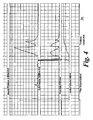
- Figure 4 illustrates the cuff pressure and the flow rate against time for a healthy volunteer.
- Figure 5 shows the resultant X-Y plot of flow rate against cuff pressure. A correction has been applied to compensate for the delay in the flow rate recording. This delay is partly due to the mechanical delay of the collecting system and partly due to the electronic filter in the flow meter.
- a plateau region 40 is defined where the cuff pressure increases without reducing the flow rate.
- a "knee" point 41 is reached which indicates this. This is the point at which the cuffed region of the urethra takes over as a flow controlling zone.
- this knee point is followed by a steady, usually linear decrease in flow rate as the cuff pressure is increased, representing the cuff flow controlling zone, shown at 42.
- the line intersects the pressure axis when the flow rate has been reduced to zero at 43. This point represents the estimate of isovolumetric bladder contraction pressure.
- a recording is made of the flow rate and the cuff pressure in the recording and analysis system 20, and an appropriate correction for the delay in the flow rate recording is applied.
- the X-Y plot of flow rate versus cuff pressure is produced. From this X-Y plot, the isovolumetric pressure where the slope intercepts the X axis at point 43 is calculated.
- the "knee" pressure 41 can be determined which represents a minimum for the contraction pressure at maximum flow.
- the cuff pressure for when the flow is reduced to 50 % , in the region 42 is used as an empirical measurement relating to bladder contraction and outlet function. Such may be useful in determining outflow resistance.
- the "knee” pressure 41 has also been determined to correspond to an important new urodynamics parameter in its own right. Consistent with the work of W Schaefer ("Urethral resistance? Urodynamic concepts of physiological and pathological bladder outlet function during voiding", Neurourology and urodynamics 4: pp161-201 ) and D J Griffiths ("Urodynamics: the mechanics and hydrodynamics of the lower urinary tract", Medical Physics Handbooks 4, Adam Hilger Ltd ), this "knee” pressure can be equated with the opening pressure of a compressive flow controlling zone. In an obstructed male, this is usually the prostate gland. The test result is therefore capable of providing information about outlet function as well as bladder contraction.
- the method of the present invention thereby offers a number of advantages not found in the prior art methods, summarised below.
- Figure 6 shows simultaneously recorded rectal pressure, bladder pressure, flow rate, voided volume and filled volume during uninterrupted voiding (on the left half of the figure) and, with detrusor pressure replaced by cuff pressure, during application of the new test (on the right half of the figure). This is for a patient with so called "low pressure, low flow”. This also illustrates how asking the patient to count can reduce abdominal straining.
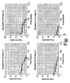
- Figure 7 shows the plot of flow rate against cuff pressure for the patient of figure 6, for each of the four interruptions. Note that normally the fourth interruption would be discounted because the flow rate does not recover after deflation of the cuff.
- Figure 8 is a full urodynamics recording for a patient with "high pressure, low flow” voiding, with the new test applied towards the end after refilling the bladder. Note the very high initial contraction which is not sustained, the pattern being detected by the decreasing cuff pressure needed to stop the flow.
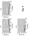
- Figure 9 is the plot of flow rate against cuff pressure for this patient for each of the three interruptions. Notice how for the first interruption, flow continues even when the maximum cuff pressure of 200 cmH 2 O (19.6kPa) is applied.
- Figure 10 summarises the data showing the correlation between data gathered simultaneously using a conventional urodynamics investigation technique and a cuff pressure test as described herein, for each of eight persons.
- the graph shows the isovolumetric bladder contraction pressure when the flow rate is reduced to zero (horizontal axis) and the cuff pressure required to reduce the flow to zero (vertical axis).
- Urologists will be aware that the isovolumetric bladder contraction pressure measured with this technique will differ from the detrusor contraction pressure measured at peak flow rate.
- the detrusor pressure can be calculated by subtracting the abdominal pressure from the bladder pressure. From examination of recordings of 6 volunteers and 16 patients, the mean abdominal pressure is 39 cmH 2 O (3.83 kPa) with a standard deviation of 10. Another important difference is that, as predicted on theoretical grounds, higher pressure can be generated by the bladder when it is not emptying fluid. In practice this difference ranges from zero to approaching 100 cmH 2 O (9.81 kPa) with most being around 20-30 cmH 2 O.
- a single tube 104 is used to connect with the pneumatic cuff.
- This tube can be used for inflation / deflation functions as well as for measuring pressure, providing that a tube of sufficiently large internal diameter is used.
- the internal diameter of the tube is 2-3 mm.
- a reservoir 151 is pressurised by the pump 130 and provides improved performance of the pressure control.
- a safety pressure switch 152 is provided to ensure that reservoir pressure (and hence pressure delivered to the cuff 2) does not exceed a safe value.
- variable orifice valve 134 is used to control inflation, allowing more flexible control and readily allowing either staircase or ramp inflation.
- a changeover valve 150 is provided to allow controlled deflation in addition to rapid deflation.
Landscapes
- Health & Medical Sciences (AREA)
- Life Sciences & Earth Sciences (AREA)
- Medical Informatics (AREA)
- Molecular Biology (AREA)
- Urology & Nephrology (AREA)
- Biophysics (AREA)
- Pathology (AREA)
- Engineering & Computer Science (AREA)
- Biomedical Technology (AREA)
- Heart & Thoracic Surgery (AREA)
- Physiology (AREA)
- Physics & Mathematics (AREA)
- Surgery (AREA)
- Animal Behavior & Ethology (AREA)
- General Health & Medical Sciences (AREA)
- Public Health (AREA)
- Veterinary Medicine (AREA)
- Measuring Pulse, Heart Rate, Blood Pressure Or Blood Flow (AREA)
- Orthopedics, Nursing, And Contraception (AREA)
- Measuring And Recording Apparatus For Diagnosis (AREA)
- Measuring Fluid Pressure (AREA)
Abstract
Description
- The present invention relates to methods and apparatus for carrying out non-invasive urodynamics investigations on male patients, and in particular to methods and apparatus for controlling urethral pressure and making measurements of bladder pressure, in order to, for example, facilitate diagnosis of, and distinction between, obstructive and non-obstructive voiding dysfunction.
- In the past, urodynamics investigations have been carried out using invasive techniques using, for example, catheters introduced into the bladder. Such catheters can be used for both filling the bladder and directly measuring pressure within the bladder, allowing a comprehensive assessment to be made. However, such invasive techniques are associated with severe patient discomfort, a degree of morbidity, and high cost both in financial terms and in time.
- It is found that a proportion of men undergoing prostatectomy do not get the anticipated benefit therefrom and many urologists believe all men should have a urodynamics study beforehand to help identify those less likely to benefit from surgery. There is a real need for a simple, easily administered, atraumatic test which will provide information similar to that currently only available from a full urodynamics study, to give objective evidence of obstruction.
- A number of prior art techniques have been proposed for non-invasive measurements on male patients. Many of these suggest the use of a condom catheter, having a stop valve and pressure measurement port, which fits over the penis and can be used to make pressure and flow rate measurements under "interrupted flow" or isovolumetric conditions. Such devices are often associated with problems of erroneous measurements arising from leakage and distortion or high compliance of the device, and can be awkward and messy to use.
- In another prior art approach, as described in Neurourology and Urodynamics 14:101-114 (1995) "Non-invasive Quantitative Method for Measuring Isovolumetric Bladder Pressure and Urethral Resistance in the Male", L P McRae et al and corresponding
US Patent 5807278 , it has been suggested to use an inflatable cuff around the penis which is initially pressurised to occlude the urethra. The patient then attempts to void so that the urethra above the occluding cuff becomes distended with urine and the static intraurethral pressure proximal to the cuff is related to the maximum isovolumetric bladder pressure. The cuff is then gradually deflated until urinary flow commences, at which point the cuff is rapidly deflated to enable volume and flow rates to be measured. Cuff pressure at the point of first urine passage can be used to assess isovolumetric bladder pressure at the commencement of voiding. No further estimate of bladder pressure is made during the subsequent voiding cycle. - Such a technique can be susceptible to a number of disadvantages. Only a single estimate of bladder contraction is made, which is at the start of the voiding cycle and is based on the occurrence of an event which can be unreliable. No further measurements are obtained to assess how well the bladder contraction is sustained during the rest of the voiding cycle. The measurement is prone to false starts due to transient events such as straining and contraction of the external sphincter which might lead to an erroneous result. It will not always be apparent that this has occurred.
- The cuff pressure must initially be elevated to a high level before commencing the test. For many subjects, this may be higher than necessary and could cause problems.
- Many patients with symptoms of obstruction can have hesitation and difficulty initiating voiding. This can make identification of the best time to start reducing the pressure difficult.
- It is an object of the present invention to provide a method and apparatus for carrying out urodynamics studies on male patients.
- It is a further object of the present invention to provide a method and apparatus for carrying out a new type of urodynamics study on male patients which provides valuable information previously only available from catheterisation and a conventional urodynamics study, but achieving this with a well tolerated, easily repeated, quick to perform, non-invasive test.
- It is a further object of the invention to provide a method and apparatus for obtaining measurements of flow rate during application of a controlled increase in pressure in a penile cuff leading to a reliable measurement of bladder isovolumetric contraction pressure or other urodynamics parameter. Preferably, this can be applied a number of times during the voiding cycle.
- According to one aspect, the present invention provides a method of making urethral pressure measurements on a male body according to the steps of
claim 1. - There is discussed in the description an apparatus for making urethral pressure measurements on a male body comprising: a pneumatic cuff adapted to fit around the penis; means for automatically inflating the cuff over a period of time during voiding of the bladder through the urethra in order to gradually occlude the urethra before voiding of the bladder is complete; and means for determining the cuff pressure at which the urethra becomes completely occluded.
- There is also discussed in the description an apparatus for making urethral pressure measurements on a male body comprising: a pneumatic cuff adapted to fit around the penis; means for automatically inflating the cuff over a period of time during voiding of the bladder through the urethra in order to gradually occlude the urethra before voiding of the bladder is complete; means for recording volume of urine flow and cuff pressure as a function of time; means for establishing, from said means for recording, a relationship between urine flow rate and cuff pressure; and means for determining, from said relationship, information about the relationship between bladder contraction and outlet function. The information may include a measure of outflow resistance.
- According to another aspect, the present invention provides an apparatus for making urethral pressure measurements on a male body according to
Claim 14. - There is also discussed in the description an apparatus for controlling urethral pressure on a male body comprising: a pneumatic cuff adapted to fit around the penis; means for automatically inflating the cuff over a period of time during voiding of the bladder through the urethra in order to gradually occlude the urethra before voiding of the bladder is complete; and means for determining the cuff pressure at which the urethra becomes completely occluded.
- Embodiments of the present invention will now be described by way of example with reference to the accompanying drawings in which:
- Figure 1 shows a schematic block diagram illustrating electrical elements of a non-invasive bladder pressure measurement system according to the present invention;
- Figure 2 shows a schematic block diagram illustrating pneumatic elements of the non-invasive bladder pressure measurement system of figure 1;
- Figure 3 shows a graph of urethral pressure against cuff pressure as a percentage, for varying cuff widths and for different subjects;
- Figure 4 shows a graph of cuff pressure and flow rate against time for a healthy subject;
- Figure 5 shows a plot of flow rate against cuff pressure from the data of figure 4;
- Figure 6 shows a series of graphs of rectal pressure, bladder pressure, detrusor pressure or cuff pressure and flow rate plotted against time, for a conventional invasive test on the left, and for a non-invasive method of the present invention on the right;
- Figure 7 shows plots of flow rate against cuff pressure from the data of figure 6, for each of the four interruptions;
- Figure 8 shows results from a full urodynamic study for a patient with high pressure, low flow voiding condition;
- Figure 9 shows plots of flow rate against cuff pressure from the data of figure 8 for each of the interruptions; and
- Figure 10 shows a graph comparing pressure data gathered using conventional invasive techniques with those gathered using the present invention;
- Figure 11 shows a schematic block diagram illustrating pneumatic and control elements of an alternative non-invasive bladder pressure measurement system to that of figures 1 and 2.
- With reference to figure 1, there is shown a schematic diagram of the main components of a non-invasive bladder
pressure measurement system 1 according to one embodiment of the invention. - A
pneumatic cuff 2, operable on similar principles to those used in blood pressure measurement, is applied to the patient'spenis 3. Thepneumatic cuff 2 preferably has two communicatingpneumatic tube connections first tube 4 connected to apneumatic pump system 5 which may be constructed according to principles well established in blood pressure measuring devices, and which is adapted to allow a controlled incremental pressure to be applied to the cuff. Asecond tube 6 communicates with a pressure sensing device 7 which has an output, preferably adapted to provide digitised, sampled measurements at predetermined time intervals, suitable for direct transfer to the input of a microprocessor-based recording andanalysis system 20. - A
urine collection mechanism 11 preferably comprises afunnel 12 or other guide andcollection vessel 13 with an electrical output for determining volume and flow rate. In the preferred embodiment shown, the collection vessel comprises aweighing device 14 which provides aweight output 15 which is connected to a volume and flowrate measurement module 16. The volume and flowrate measurement module 16 is adapted to calculate urine volume as a function of time and provide digitised flow rate and volume measurements to the microprocessor-based recording andanalysis system 20. - The
pneumatic pump system 5, pressure sensing device 7, volume and flowrate measurement module 16 and recording andanalysis system 20 may all be coupled to acontrol microprocessor 10 to co-ordinate the functions of the various parts. It will be understood that thecontrol microprocessor 10 and the recording andanalysis system 20 may be provided as a suitably programmed computer, or by customised hardware. - Data output from the recording and
analysis system 20 may be provided on any suitable output device such as VDU monitor, printer or disk. - Referring now to figure 2, further details of a preferred pneumatic system forming the main components of
pneumatic pump system 5 andcontrol microprocessor 10 of figure 1 are described. - A
pump 30 provides for the pressurisation of the system via a oneway valve 31 and solenoid valve 32. In a preferred embodiment, the pump provides an air reservoir upstream of the solenoid valve 32 at approximately 300 cmH2O (29.4kPa) pressure. Apressure transducer 33 provides feedback of this pump pressure upstream of the solenoid valve 32 to control thepump 30. - Downstream of the solenoid valve 32 a
flow restrictor 34 prevents over-inflation of thecuff 2 which is connected, by theinflation tube 4, to the downstream side of the solenoid valve 32 andflow restrictor 34. Thesecond tube 6 is connected to apressure sensing device 38. Adifferential pressure switch 35 provides for communication between the first and second tubes as a safety device in the event of blockage within thecuff 2 or one of thetube connections - The cuff and pneumatic system is connected to a
depressurisation line 36 connected to asecond solenoid valve 37. Thepump 30 andsolenoid valves 32, 37 are under the control ofmicroprocessor controller 10, which may also be connected to receive signals from thepressure transducers 33, 7. For ensuring safety, the pressure in the cuff is restricted to a suitable maximum, eg. 200 cmH2O (19.6kPa), in the preferred embodiment. - In the preferred embodiment, the cuff should have a width exceeding the diameter of the penis. In comparative tests using pressure transducers, pressure measurements were made using cuff widths of 3.7 cm, 4.6 cm and 5.4 cm. Using the widest practicable cuff has been demonstrated to produce the most consistent measurements. Illustrative results for four patients, showing urethral pressure (Pure) against cuff pressure (Pcuff) as a percentage and for varying cuff widths are shown in figure 3.
- In operation, the bladder
pressure measurement system 1 is adapted to obtain a series of measurements of the volume of urine passed and the cuff pressure, as a function of time, over a period during which (a) the patient commences voiding of the bladder with the cuff deflated, and (b) thepump 30 commences gradual inflation of thecuff 2 until urine flow is stopped. The cuff pressure is then plotted as a function of flow rate to produce a relationship therebetween. - Preferably, the cuff is inflated in incremental steps of, for example, 10 cmH2O (981 Pa) and pressure measurements are made between each increment. In the preferred embodiment, the incremental steps last for between 0.5 sec and 1.0 sec, with a preferred value of approximately 0.75 sec. However, a continuously variable rate of inflation may be used if appropriate.
- The optimum rate for incremental increase depends in part upon the speed of response of the
flow meter - The technique relies on two assumptions. Firstly, if, while the bladder is emptying, the stream is interrupted by introducing a blockage, then once stasis is established the pressure in the urethra proximal to the blockage equates to the bladder pressure, apart from the hydrostatic height difference between the bladder and the cuff. Simultaneous fluoroscopy has shown the urethra to remain open and pressure measurement within the urethra has shown this assumption to be valid.
- Secondly, when blockage is caused by inflation of a cuff around the penis, it is assumed that the pressure in the cuff is transmitted to the walls of the penile urethra and that when this exceeds the bladder pressure, flow is interrupted. This is similar to the assumption made when blood pressure is routinely measured. This assumption has been assessed by simultaneous penile urethral pressure measurements as illustrated in figure 3.
- Figure 4 illustrates the cuff pressure and the flow rate against time for a healthy volunteer. Figure 5 shows the resultant X-Y plot of flow rate against cuff pressure. A correction has been applied to compensate for the delay in the flow rate recording. This delay is partly due to the mechanical delay of the collecting system and partly due to the electronic filter in the flow meter.
- Four distinct features can be identified in this graph. Firstly, a
plateau region 40 is defined where the cuff pressure increases without reducing the flow rate. Secondly, when the distal resistance imposed by the cuff exceeds a certain level it starts reducing the flow rate and a "knee"point 41 is reached which indicates this. This is the point at which the cuffed region of the urethra takes over as a flow controlling zone. Thirdly, this knee point is followed by a steady, usually linear decrease in flow rate as the cuff pressure is increased, representing the cuff flow controlling zone, shown at 42. Fourthly, the line intersects the pressure axis when the flow rate has been reduced to zero at 43. This point represents the estimate of isovolumetric bladder contraction pressure. - Thus, following the method of the present invention, using the
measurement system 1 under the control ofmicroprocessor 10, a recording is made of the flow rate and the cuff pressure in the recording andanalysis system 20, and an appropriate correction for the delay in the flow rate recording is applied. The X-Y plot of flow rate versus cuff pressure is produced. From this X-Y plot, the isovolumetric pressure where the slope intercepts the X axis atpoint 43 is calculated. In addition, the "knee"pressure 41 can be determined which represents a minimum for the contraction pressure at maximum flow. In addition, the cuff pressure for when the flow is reduced to 50 % , in theregion 42, is used as an empirical measurement relating to bladder contraction and outlet function. Such may be useful in determining outflow resistance. - The "knee"
pressure 41 has also been determined to correspond to an important new urodynamics parameter in its own right. Consistent with the work of W Schaefer ("Urethral resistance? Urodynamic concepts of physiological and pathological bladder outlet function during voiding", Neurourology and urodynamics 4: pp161-201) and D J Griffiths ("Urodynamics: the mechanics and hydrodynamics of the lower urinary tract", ), this "knee" pressure can be equated with the opening pressure of a compressive flow controlling zone. In an obstructed male, this is usually the prostate gland. The test result is therefore capable of providing information about outlet function as well as bladder contraction. - The method of the present invention thereby offers a number of advantages not found in the prior art methods, summarised below.
- a) The use of the decreasing flow rate versus cuff pressure graph provides a much more reliable measurement of the isovolumetric bladder pressure than do the measurement techniques using a potentially erroneous single measurement at the start of flow.
- b) The test is applied after voiding starts which avoids any problems associated with false starts.
- c) The pressure flow plot allows complex voiding patterns to be recognised by the skilled clinician.
- d) The method can be applied repeatedly at intervals during the course of voiding to assess how well the bladder contraction is sustained.
- e) The transient rise in flow rate after the pressure in the cuff is released can also be used in a similar way to that proposed in the prior art methods, in addition to any measurements made according the steps identified above. Further, by comparison, the efficacy of the initial flow rate is indicated.
- f) The cuff pressure at the "knee" of the curve is believed to represent a useful measure of the minimum for the bladder pressure at peak flow and is equated to the opening pressure of a compressive flow controlling zone, often the prostate gland.
- g) The cuff pressure at which the flow is reduced to 50% is an empirical measurement which relates to the relationship between bladder contraction and outlet function.
- h) Evidence suggests that, for some patients, as the cuff pressure is incremented, there is a temporary reduction in, and then recovery of, flow rate. This is consistent with a small expansion of the proximal urethra because of its compliance each time the cuff pressure increases. This is most apparent when using a flow meter which gives a high frequency response. There is therefore additional information to be gained on the relationship between bladder contraction and outlet function by the use of a flow metering system in which mechanical delay (from the collection system) and electronic delay (from any signal processing such as filtering etc.) are minimised as far as possible.
- i) The test is less dependent on the patient's co-operation, and therefore less susceptible to variation.
- Figure 6 shows simultaneously recorded rectal pressure, bladder pressure, flow rate, voided volume and filled volume during uninterrupted voiding (on the left half of the figure) and, with detrusor pressure replaced by cuff pressure, during application of the new test (on the right half of the figure). This is for a patient with so called "low pressure, low flow". This also illustrates how asking the patient to count can reduce abdominal straining.
- Figure 7 shows the plot of flow rate against cuff pressure for the patient of figure 6, for each of the four interruptions. Note that normally the fourth interruption would be discounted because the flow rate does not recover after deflation of the cuff.
- Figure 8 is a full urodynamics recording for a patient with "high pressure, low flow" voiding, with the new test applied towards the end after refilling the bladder. Note the very high initial contraction which is not sustained, the pattern being detected by the decreasing cuff pressure needed to stop the flow.
- Figure 9 is the plot of flow rate against cuff pressure for this patient for each of the three interruptions. Notice how for the first interruption, flow continues even when the maximum cuff pressure of 200 cmH2O (19.6kPa) is applied.
- Figure 10 summarises the data showing the correlation between data gathered simultaneously using a conventional urodynamics investigation technique and a cuff pressure test as described herein, for each of eight persons. The graph shows the isovolumetric bladder contraction pressure when the flow rate is reduced to zero (horizontal axis) and the cuff pressure required to reduce the flow to zero (vertical axis).
- Urologists will be aware that the isovolumetric bladder contraction pressure measured with this technique will differ from the detrusor contraction pressure measured at peak flow rate. The detrusor pressure can be calculated by subtracting the abdominal pressure from the bladder pressure. From examination of recordings of 6 volunteers and 16 patients, the mean abdominal pressure is 39 cmH2O (3.83 kPa) with a standard deviation of 10. Another important difference is that, as predicted on theoretical grounds, higher pressure can be generated by the bladder when it is not emptying fluid. In practice this difference ranges from zero to approaching 100 cmH2O (9.81 kPa) with most being around 20-30 cmH2O. (1.96-2.94kPa) In the cases of unusually high increase, this is normally associated with a curved, more asymptotic approach to zero of the flow rate as the cuff pressure rises. In the group of patients with obstruction, it is Likely that they will be operating closer to their maximum before the cuff pressure is increased.
- Some patients with obstruction have developed the habit of recruiting their abdominal muscles to try to assist with emptying the bladder. This is often self defeating as the pressure also applies to the urethra beyond the obstruction negating any benefit. In the measurement methods described above, this is readily apparent if it is occurring, because the flow rate recording is erratic. We have introduced the technique for such patients of asking them to count aloud while emptying the bladder. This makes it much more difficult for them to strain their abdominal muscles during the test which gives a more meaningful result. Figure 7 discussed previously illustrates the use and benefit of this technique.
- With reference to figure 11, there is shown an alternative pneumatic control system. Where items in this figure have the same or similar function to those indicated with reference to figure 2, the reference numerals are the same subject to the addition of one hundred, and will not be further described in any detail.
- In the embodiment of figure 11, a
single tube 104 is used to connect with the pneumatic cuff. This tube can be used for inflation / deflation functions as well as for measuring pressure, providing that a tube of sufficiently large internal diameter is used. In a preferred embodiment, the internal diameter of the tube is 2-3 mm. - A
reservoir 151 is pressurised by thepump 130 and provides improved performance of the pressure control. Asafety pressure switch 152 is provided to ensure that reservoir pressure (and hence pressure delivered to the cuff 2) does not exceed a safe value. - A
variable orifice valve 134 is used to control inflation, allowing more flexible control and readily allowing either staircase or ramp inflation. Achangeover valve 150 is provided to allow controlled deflation in addition to rapid deflation.
Claims (19)
- A method of making urethral pressure measurements on a male body comprising the steps of:(a) attaching a pneumatic cuff (2) around the penis (3);(b) after commencement of urine flow through the penis (3), automatically inflating the cuff (2) over a period of time in order to gradually occlude the urethra before voiding of the bladder is complete;(c) establishing a relationship between the urine flow and the cuff pressure applied; and(d) using said established relationship to determine a pressure measurement related to the urethral pressure under isovolumetric conditions.
- A method according to claim 1 in which said urethral pressure measurement is used to deduce bladder pressure.
- A method according to claim 1 in which the cuff (2) is inflated in incremental steps over said period of time, with pressure and flow measurements being made between each increment.
- A method according to claim 3 in which the incremental steps are applied at approximately 0.5 to 1.0 second intervals.
- A method according to claim 3 or claim 4 in which the incremental steps are approximately 10 cmH2O (981 Pa).
- A method according to claim 1 further including the step of obtaining a series of measurements of the volume of urine passed over time, commencing at a low cuff pressure insufficient to cause significant reduction of urine flow and during the period of increasing cuff pressure until the urine flow has substantially ceased.
- A method according to claim 6 further including the steps of :using said series of measurements to plot the relationship between cuff pressure and flow rate, andcomputing an intercept, from said series of measurements, with the cuff pressure axis to deduce an accurate value of cuff pressure when the flow rate is zero.
- A method according to claim 7 further including the step of using said intercept value as a measure of the isovolumetric bladder contraction pressure.
- A method according to claim 1 further including the steps of:deflating the cuff (2) when the urine flow has been stopped; andrepeating the steps (b) to (d) of claim 1 thereafter at least once.
- A method according to claim 1 further including the steps of obtaining a series of measurements of the volume of urine passed over time, using said series of measurements to plot the relationship between cuff pressure and flow rate, and identifying a knee point (41) on the relationship between cuff pressure and flow rate when the flow rate starts to fall.
- A method according to claim 10 further including the step of using said knee point (41) as a measure of the minimum value for the bladder contraction pressure at maximum flow.
- A method according to claim 10 further including the step of determining a pressure at the knee point (41) as corresponding to the opening pressure of a compressive flow controlling zone (42).
- A method according to claim 10 further including the step of identifying an intermediate point on the relationship at approximately 50% of flow rate value determined by said knee point (41), and using the cuff pressure value at said intermediate point as an empirical measurement relating bladder contraction to outlet function.
- Apparatus for making urethral pressure measurements on a male body comprising:a pneumatic cuff (2) adapted to fit around the penis (3);means (4, 5) adapted to automatically inflate the cuff (2) over a period of time during voiding of the bladder through the urethra in order to gradually occlude the urethra before voiding of the bladder is complete;means (20) adapted to record the volume of urine flow and cuff pressure as a function of time during said period of time;means (20) adapted to establish, from said means for recording, a relationship between urine flow rate and cuff pressure; andmeans (20) adapted to determine from said relationship, a pressure measurement related to at least one of isovolumetric bladder pressure, a minimum value (41) for the contraction pressure at maximum flow and opening pressure of a compressive flow controlling zone (42).
- Apparatus according to claim 14 in which the means (20) adapted to determine is configured to determine the cuff pressure at which the urethra becomes completely occluded.
- Apparatus according to claim 14 in which the means (4, 5) adapted to automatically inflate said cuff (20) is configured to inflate the cuff by incremental steps at a predetermined rate.
- Apparatus according to claim 14 in which the means (20) adapted to determine is configured to determine a knee point (41) on said relationship between urine flow rate and cuff pressure when the flow rate starts to fall, and to output said knee point (41) as a measure of the minimum value for the contraction pressure at maximum flow and as an estimate of the opening pressure of a compressive flow controlling zone.
- Apparatus according to claim 14 in which the means (20) adapted to determine is configured to determine an intermediate point on said relationship between urine flow rate and cuff pressure at approximately 50% of flow rate value determined by said knee point (41), and to output the cuff pressure value at said intemiediate point as an empirical measurement relating bladder contraction to outlet function.
- Apparatus according to claim 14 in which the means (20) adapted to determine is configured to determine from said relationship between urine flow rate and cuff pressure, information about the relationship between bladder contraction and outlet function.
Applications Claiming Priority (3)
| Application Number | Priority Date | Filing Date | Title |
|---|---|---|---|
| GB9824333 | 1998-11-07 | ||
| GBGB9824333.0A GB9824333D0 (en) | 1998-11-07 | 1998-11-07 | Non-invasive bladder pressure measurements |
| PCT/GB1999/003612 WO2000027285A1 (en) | 1998-11-07 | 1999-11-02 | Non-invasive bladder pressure measurements |
Publications (2)
| Publication Number | Publication Date |
|---|---|
| EP1124486A1 EP1124486A1 (en) | 2001-08-22 |
| EP1124486B1 true EP1124486B1 (en) | 2007-07-25 |
Family
ID=10841951
Family Applications (1)
| Application Number | Title | Priority Date | Filing Date |
|---|---|---|---|
| EP99952691A Expired - Lifetime EP1124486B1 (en) | 1998-11-07 | 1999-11-02 | Non-invasive bladder pressure measurements |
Country Status (8)
| Country | Link |
|---|---|
| US (1) | US6506169B2 (en) |
| EP (1) | EP1124486B1 (en) |
| AT (1) | ATE367766T1 (en) |
| AU (1) | AU6480599A (en) |
| DE (1) | DE69936661T2 (en) |
| ES (1) | ES2292253T3 (en) |
| GB (1) | GB9824333D0 (en) |
| WO (1) | WO2000027285A1 (en) |
Families Citing this family (14)
| Publication number | Priority date | Publication date | Assignee | Title |
|---|---|---|---|---|
| GB0010803D0 (en) * | 2000-05-04 | 2000-06-28 | Univ Brighton | Fluid delivery device |
| CN1289028C (en) * | 2001-06-29 | 2006-12-13 | 伊西康公司 | Systems for Assessing Urinary Function |
| WO2003024330A2 (en) * | 2001-09-17 | 2003-03-27 | Bioflo Systems, Inc. | Non-invasive diagnostic systems for lower urinary tract disorders |
| US6805662B2 (en) | 2003-02-18 | 2004-10-19 | Polyzen, Inc. | Urinary incontinence control device and method of use |
| CA2584162C (en) * | 2004-10-21 | 2017-11-28 | Optiscan Biomedical Corporation | Method and apparatus for determining an analyte concentration in a sample having interferents |
| AU2007266326B2 (en) * | 2006-05-30 | 2013-08-01 | Colin Dunlop | Blood pressure monitor |
| US7758519B2 (en) * | 2006-09-08 | 2010-07-20 | University Of Vermont And State Agriculture College | Systems for and methods of assessing lower urinary tract function via sound analysis |
| US7811237B2 (en) * | 2006-09-08 | 2010-10-12 | University Of Vermont And State Agricultural College | Systems for and methods of assessing urinary flow rate via sound analysis |
| GB0908766D0 (en) * | 2009-05-21 | 2009-07-01 | Newcastle Upon Tyne Hospitals | Method and apparatus for measuring bladder pressure |
| GB201113749D0 (en) * | 2011-08-10 | 2011-09-21 | Newcastle Upon Tyne Hospitals Nhs Foundation Trust | Urine flow measuring apparatus |
| US9277884B2 (en) | 2013-03-14 | 2016-03-08 | Biofluid Technology, Inc. | Devices and methods for tissue immobilization and non-invasive lower urinary tract analysis |
| CN104665850A (en) * | 2015-03-27 | 2015-06-03 | 江苏苏云医疗器材有限公司 | Training device for evaluating pressure and volume of bladder |
| CA3259714C (en) | 2018-02-22 | 2026-04-14 | Srs Medical Systems, Llc | Urodynamic investigation apparatus, system, & methods |
| GB201916125D0 (en) | 2019-11-06 | 2019-12-18 | Heaviside Ltd | Pressure measurement device |
Family Cites Families (8)
| Publication number | Priority date | Publication date | Assignee | Title |
|---|---|---|---|---|
| US3523522A (en) * | 1964-12-24 | 1970-08-11 | Technicon Corp | Apparatus for correlating body fluid samples with respective source individuals |
| US3511241A (en) * | 1966-06-23 | 1970-05-12 | John W Lee | Incontinence device for the male patient |
| US3769497A (en) * | 1971-09-10 | 1973-10-30 | Hoffmann La Roche | Urine liquid discharge monitor |
| US4532936A (en) * | 1981-08-21 | 1985-08-06 | Leveen Eric G | Automatic urine flow meter |
| US5377101A (en) * | 1992-02-21 | 1994-12-27 | Rollema; Harm J. | Urinary flow classification system and method |
| US5616138A (en) * | 1995-08-29 | 1997-04-01 | Tri State Hospital Supply Corporation | Urine drainage and collection device |
| US5807278A (en) * | 1996-06-06 | 1998-09-15 | Mcrae; Lorin P. | Noninvasive bladder pressure and urine flow measurement apparatus and method |
| US5823972A (en) * | 1996-06-06 | 1998-10-20 | Mcrae; Lorin P. | Pressure transducer bladder pressure and urinary flow measurement apparatus and method |
-
1998
- 1998-11-07 GB GBGB9824333.0A patent/GB9824333D0/en not_active Ceased
-
1999
- 1999-11-02 ES ES99952691T patent/ES2292253T3/en not_active Expired - Lifetime
- 1999-11-02 DE DE69936661T patent/DE69936661T2/en not_active Expired - Lifetime
- 1999-11-02 WO PCT/GB1999/003612 patent/WO2000027285A1/en not_active Ceased
- 1999-11-02 AU AU64805/99A patent/AU6480599A/en not_active Abandoned
- 1999-11-02 EP EP99952691A patent/EP1124486B1/en not_active Expired - Lifetime
- 1999-11-02 AT AT99952691T patent/ATE367766T1/en not_active IP Right Cessation
-
2001
- 2001-05-04 US US09/849,952 patent/US6506169B2/en not_active Expired - Lifetime
Non-Patent Citations (1)
| Title |
|---|
| None * |
Also Published As
| Publication number | Publication date |
|---|---|
| ATE367766T1 (en) | 2007-08-15 |
| AU6480599A (en) | 2000-05-29 |
| ES2292253T3 (en) | 2008-03-01 |
| DE69936661D1 (en) | 2007-09-06 |
| WO2000027285A1 (en) | 2000-05-18 |
| DE69936661T2 (en) | 2008-05-21 |
| EP1124486A1 (en) | 2001-08-22 |
| US20020010404A1 (en) | 2002-01-24 |
| US6506169B2 (en) | 2003-01-14 |
| GB9824333D0 (en) | 1998-12-30 |
Similar Documents
| Publication | Publication Date | Title |
|---|---|---|
| US6506169B2 (en) | Non-invasive bladder pressure measurements | |
| US5823972A (en) | Pressure transducer bladder pressure and urinary flow measurement apparatus and method | |
| US5807278A (en) | Noninvasive bladder pressure and urine flow measurement apparatus and method | |
| US7252631B2 (en) | System and method for assessing detrusor instability | |
| Bates et al. | The standardization of terminology of lower urinary tract function | |
| US6719709B2 (en) | Diagnostic urethral assembly and method | |
| EP1121065B1 (en) | Device for treating urinary retention | |
| US7004899B2 (en) | System and method for assessing urinary function | |
| Ulmsten et al. | A new technique for simultaneous urethrocystometry including measurements of the urethral pressure profile | |
| Awad et al. | Urethral pressure profile in female stress incontinence | |
| McRae et al. | Noninvasive quantitative method for measuring isovolumetric bladder pressure and urethral resistance in the male: I. Experimental validation of the theory | |
| JP7242688B2 (en) | urodynamic tester | |
| WO2025056914A1 (en) | Urology catheter | |
| Sullivan et al. | Penile urethral compression‐release maneuver as a non‐invasive screening test for diagnosing prostatic obstruction | |
| EP2432396B1 (en) | Method and apparatus for measuring bladder pressure | |
| Gershon et al. | Urodynamic evaluation of female stress urinary incontinence | |
| Richardson | Reduction of urethral pressure in response to stress: Relationship to urethral mobility | |
| Webster et al. | Value of subtracted bladder pressure measurement in routine urodynamics | |
| Lotze | A comparison of external transducers and microtransducers in urodynamic studies of female patients | |
| Versi | Relevance of urethral pressure profilometry to date | |
| Klarskov | Tests of Urethral Function | |
| Thind et al. | Pressure response to rapid dilation of resting urethra in healthy women | |
| Blake et al. | Evaluation of the non-invasive estimation of bladder pressure using a penile cuff. An alternative to pressure-flow studies in men? | |
| Lindström et al. | Some methodological aspects on the measurement of intraluminal pressures in the female urogenital tract in vivo | |
| HARADA et al. | Simultaneous Recording of Urethral Pressure and Cross Sectional Area Profile |
Legal Events
| Date | Code | Title | Description |
|---|---|---|---|
| PUAI | Public reference made under article 153(3) epc to a published international application that has entered the european phase |
Free format text: ORIGINAL CODE: 0009012 |
|
| 17P | Request for examination filed |
Effective date: 20010504 |
|
| AK | Designated contracting states |
Kind code of ref document: A1 Designated state(s): AT BE CH CY DE DK ES FI FR GB GR IE IT LI LU MC NL PT SE |
|
| AX | Request for extension of the european patent |
Free format text: AL;LT;LV;MK;RO;SI |
|
| 17Q | First examination report despatched |
Effective date: 20050215 |
|
| GRAP | Despatch of communication of intention to grant a patent |
Free format text: ORIGINAL CODE: EPIDOSNIGR1 |
|
| RAP1 | Party data changed (applicant data changed or rights of an application transferred) |
Owner name: MEDIPLUS LIMITED |
|
| GRAS | Grant fee paid |
Free format text: ORIGINAL CODE: EPIDOSNIGR3 |
|
| GRAA | (expected) grant |
Free format text: ORIGINAL CODE: 0009210 |
|
| AK | Designated contracting states |
Kind code of ref document: B1 Designated state(s): AT BE CH CY DE DK ES FI FR GB GR IE IT LI LU MC NL PT SE |
|
| REG | Reference to a national code |
Ref country code: GB Ref legal event code: FG4D |
|
| REG | Reference to a national code |
Ref country code: CH Ref legal event code: EP |
|
| REG | Reference to a national code |
Ref country code: IE Ref legal event code: FG4D |
|
| REF | Corresponds to: |
Ref document number: 69936661 Country of ref document: DE Date of ref document: 20070906 Kind code of ref document: P |
|
| ET | Fr: translation filed | ||
| PG25 | Lapsed in a contracting state [announced via postgrant information from national office to epo] |
Ref country code: PT Free format text: LAPSE BECAUSE OF FAILURE TO SUBMIT A TRANSLATION OF THE DESCRIPTION OR TO PAY THE FEE WITHIN THE PRESCRIBED TIME-LIMIT Effective date: 20071226 Ref country code: NL Free format text: LAPSE BECAUSE OF FAILURE TO SUBMIT A TRANSLATION OF THE DESCRIPTION OR TO PAY THE FEE WITHIN THE PRESCRIBED TIME-LIMIT Effective date: 20070725 Ref country code: FI Free format text: LAPSE BECAUSE OF FAILURE TO SUBMIT A TRANSLATION OF THE DESCRIPTION OR TO PAY THE FEE WITHIN THE PRESCRIBED TIME-LIMIT Effective date: 20070725 |
|
| REG | Reference to a national code |
Ref country code: CH Ref legal event code: PL |
|
| NLV1 | Nl: lapsed or annulled due to failure to fulfill the requirements of art. 29p and 29m of the patents act | ||
| PG25 | Lapsed in a contracting state [announced via postgrant information from national office to epo] |
Ref country code: CH Free format text: LAPSE BECAUSE OF FAILURE TO SUBMIT A TRANSLATION OF THE DESCRIPTION OR TO PAY THE FEE WITHIN THE PRESCRIBED TIME-LIMIT Effective date: 20070725 Ref country code: LI Free format text: LAPSE BECAUSE OF FAILURE TO SUBMIT A TRANSLATION OF THE DESCRIPTION OR TO PAY THE FEE WITHIN THE PRESCRIBED TIME-LIMIT Effective date: 20070725 Ref country code: AT Free format text: LAPSE BECAUSE OF FAILURE TO SUBMIT A TRANSLATION OF THE DESCRIPTION OR TO PAY THE FEE WITHIN THE PRESCRIBED TIME-LIMIT Effective date: 20070725 |
|
| REG | Reference to a national code |
Ref country code: ES Ref legal event code: FG2A Ref document number: 2292253 Country of ref document: ES Kind code of ref document: T3 |
|
| PG25 | Lapsed in a contracting state [announced via postgrant information from national office to epo] |
Ref country code: BE Free format text: LAPSE BECAUSE OF FAILURE TO SUBMIT A TRANSLATION OF THE DESCRIPTION OR TO PAY THE FEE WITHIN THE PRESCRIBED TIME-LIMIT Effective date: 20070725 |
|
| PG25 | Lapsed in a contracting state [announced via postgrant information from national office to epo] |
Ref country code: GR Free format text: LAPSE BECAUSE OF FAILURE TO SUBMIT A TRANSLATION OF THE DESCRIPTION OR TO PAY THE FEE WITHIN THE PRESCRIBED TIME-LIMIT Effective date: 20071026 Ref country code: DK Free format text: LAPSE BECAUSE OF FAILURE TO SUBMIT A TRANSLATION OF THE DESCRIPTION OR TO PAY THE FEE WITHIN THE PRESCRIBED TIME-LIMIT Effective date: 20070725 |
|
| PLBE | No opposition filed within time limit |
Free format text: ORIGINAL CODE: 0009261 |
|
| STAA | Information on the status of an ep patent application or granted ep patent |
Free format text: STATUS: NO OPPOSITION FILED WITHIN TIME LIMIT |
|
| PG25 | Lapsed in a contracting state [announced via postgrant information from national office to epo] |
Ref country code: SE Free format text: LAPSE BECAUSE OF FAILURE TO SUBMIT A TRANSLATION OF THE DESCRIPTION OR TO PAY THE FEE WITHIN THE PRESCRIBED TIME-LIMIT Effective date: 20071025 Ref country code: MC Free format text: LAPSE BECAUSE OF NON-PAYMENT OF DUE FEES Effective date: 20071130 |
|
| 26N | No opposition filed |
Effective date: 20080428 |
|
| PG25 | Lapsed in a contracting state [announced via postgrant information from national office to epo] |
Ref country code: IE Free format text: LAPSE BECAUSE OF NON-PAYMENT OF DUE FEES Effective date: 20071102 |
|
| PG25 | Lapsed in a contracting state [announced via postgrant information from national office to epo] |
Ref country code: CY Free format text: LAPSE BECAUSE OF FAILURE TO SUBMIT A TRANSLATION OF THE DESCRIPTION OR TO PAY THE FEE WITHIN THE PRESCRIBED TIME-LIMIT Effective date: 20070725 |
|
| PG25 | Lapsed in a contracting state [announced via postgrant information from national office to epo] |
Ref country code: LU Free format text: LAPSE BECAUSE OF NON-PAYMENT OF DUE FEES Effective date: 20071102 |
|
| REG | Reference to a national code |
Ref country code: FR Ref legal event code: PLFP Year of fee payment: 17 |
|
| REG | Reference to a national code |
Ref country code: FR Ref legal event code: PLFP Year of fee payment: 18 |
|
| REG | Reference to a national code |
Ref country code: FR Ref legal event code: PLFP Year of fee payment: 19 |
|
| REG | Reference to a national code |
Ref country code: DE Ref legal event code: R082 Ref document number: 69936661 Country of ref document: DE Representative=s name: FLACH BAUER STAHL PATENTANWAELTE PARTNERSCHAFT, DE |
|
| REG | Reference to a national code |
Ref country code: FR Ref legal event code: PLFP Year of fee payment: 20 |
|
| PGFP | Annual fee paid to national office [announced via postgrant information from national office to epo] |
Ref country code: FR Payment date: 20180913 Year of fee payment: 20 |
|
| PGFP | Annual fee paid to national office [announced via postgrant information from national office to epo] |
Ref country code: DE Payment date: 20181023 Year of fee payment: 20 |
|
| PGFP | Annual fee paid to national office [announced via postgrant information from national office to epo] |
Ref country code: GB Payment date: 20181031 Year of fee payment: 20 Ref country code: IT Payment date: 20181122 Year of fee payment: 20 Ref country code: ES Payment date: 20181203 Year of fee payment: 20 |
|
| REG | Reference to a national code |
Ref country code: DE Ref legal event code: R071 Ref document number: 69936661 Country of ref document: DE |
|
| REG | Reference to a national code |
Ref country code: GB Ref legal event code: PE20 Expiry date: 20191101 |
|
| PG25 | Lapsed in a contracting state [announced via postgrant information from national office to epo] |
Ref country code: GB Free format text: LAPSE BECAUSE OF EXPIRATION OF PROTECTION Effective date: 20191101 |
|
| REG | Reference to a national code |
Ref country code: ES Ref legal event code: FD2A Effective date: 20201106 |
|
| PG25 | Lapsed in a contracting state [announced via postgrant information from national office to epo] |
Ref country code: ES Free format text: LAPSE BECAUSE OF EXPIRATION OF PROTECTION Effective date: 20191103 |