EP1124408B1 - Convertisseur pour machine électrique - Google Patents
Convertisseur pour machine électrique Download PDFInfo
- Publication number
- EP1124408B1 EP1124408B1 EP01400342A EP01400342A EP1124408B1 EP 1124408 B1 EP1124408 B1 EP 1124408B1 EP 01400342 A EP01400342 A EP 01400342A EP 01400342 A EP01400342 A EP 01400342A EP 1124408 B1 EP1124408 B1 EP 1124408B1
- Authority
- EP
- European Patent Office
- Prior art keywords
- cards
- fact
- converter
- card
- box
- Prior art date
- Legal status (The legal status is an assumption and is not a legal conclusion. Google has not performed a legal analysis and makes no representation as to the accuracy of the status listed.)
- Expired - Lifetime
Links
- 239000011347 resin Substances 0.000 claims description 7
- 229920005989 resin Polymers 0.000 claims description 7
- 238000004519 manufacturing process Methods 0.000 claims description 3
- 238000000465 moulding Methods 0.000 claims description 2
- 238000009413 insulation Methods 0.000 claims 1
- 239000000543 intermediate Substances 0.000 description 17
- 238000001816 cooling Methods 0.000 description 4
- 229910052782 aluminium Inorganic materials 0.000 description 2
- XAGFODPZIPBFFR-UHFFFAOYSA-N aluminium Chemical compound [Al] XAGFODPZIPBFFR-UHFFFAOYSA-N 0.000 description 2
- 230000004888 barrier function Effects 0.000 description 2
- 238000004140 cleaning Methods 0.000 description 2
- 239000004020 conductor Substances 0.000 description 2
- 238000001746 injection moulding Methods 0.000 description 2
- 241001417523 Plesiopidae Species 0.000 description 1
- 230000006978 adaptation Effects 0.000 description 1
- 230000005540 biological transmission Effects 0.000 description 1
- 238000005266 casting Methods 0.000 description 1
- 238000010292 electrical insulation Methods 0.000 description 1
- 238000002955 isolation Methods 0.000 description 1
- 229910052751 metal Inorganic materials 0.000 description 1
- 239000002184 metal Substances 0.000 description 1
- 239000004065 semiconductor Substances 0.000 description 1
- 229910000679 solder Inorganic materials 0.000 description 1
- 230000003068 static effect Effects 0.000 description 1
- 230000001360 synchronised effect Effects 0.000 description 1
- 238000003466 welding Methods 0.000 description 1
Images


Classifications
-
- H—ELECTRICITY
- H02—GENERATION; CONVERSION OR DISTRIBUTION OF ELECTRIC POWER
- H02K—DYNAMO-ELECTRIC MACHINES
- H02K11/00—Structural association of dynamo-electric machines with electric components or with devices for shielding, monitoring or protection
- H02K11/30—Structural association with control circuits or drive circuits
- H02K11/33—Drive circuits, e.g. power electronics
-
- H—ELECTRICITY
- H05—ELECTRIC TECHNIQUES NOT OTHERWISE PROVIDED FOR
- H05K—PRINTED CIRCUITS; CASINGS OR CONSTRUCTIONAL DETAILS OF ELECTRIC APPARATUS; MANUFACTURE OF ASSEMBLAGES OF ELECTRICAL COMPONENTS
- H05K1/00—Printed circuits
- H05K1/02—Details
- H05K1/14—Structural association of two or more printed circuits
-
- H—ELECTRICITY
- H05—ELECTRIC TECHNIQUES NOT OTHERWISE PROVIDED FOR
- H05K—PRINTED CIRCUITS; CASINGS OR CONSTRUCTIONAL DETAILS OF ELECTRIC APPARATUS; MANUFACTURE OF ASSEMBLAGES OF ELECTRICAL COMPONENTS
- H05K5/00—Casings, cabinets or drawers for electric apparatus
- H05K5/02—Details
- H05K5/0204—Mounting supporting structures on the outside of casings
-
- H—ELECTRICITY
- H05—ELECTRIC TECHNIQUES NOT OTHERWISE PROVIDED FOR
- H05K—PRINTED CIRCUITS; CASINGS OR CONSTRUCTIONAL DETAILS OF ELECTRIC APPARATUS; MANUFACTURE OF ASSEMBLAGES OF ELECTRICAL COMPONENTS
- H05K7/00—Constructional details common to different types of electric apparatus
- H05K7/14—Mounting supporting structure in casing or on frame or rack
- H05K7/1422—Printed circuit boards receptacles, e.g. stacked structures, electronic circuit modules or box like frames
- H05K7/1427—Housings
- H05K7/1432—Housings specially adapted for power drive units or power converters
- H05K7/14322—Housings specially adapted for power drive units or power converters wherein the control and power circuits of a power converter are arranged within the same casing
-
- H—ELECTRICITY
- H05—ELECTRIC TECHNIQUES NOT OTHERWISE PROVIDED FOR
- H05K—PRINTED CIRCUITS; CASINGS OR CONSTRUCTIONAL DETAILS OF ELECTRIC APPARATUS; MANUFACTURE OF ASSEMBLAGES OF ELECTRICAL COMPONENTS
- H05K7/00—Constructional details common to different types of electric apparatus
- H05K7/20—Modifications to facilitate cooling, ventilating, or heating
- H05K7/2089—Modifications to facilitate cooling, ventilating, or heating for power electronics, e.g. for inverters for controlling motor
- H05K7/209—Heat transfer by conduction from internal heat source to heat radiating structure
-
- H—ELECTRICITY
- H02—GENERATION; CONVERSION OR DISTRIBUTION OF ELECTRIC POWER
- H02K—DYNAMO-ELECTRIC MACHINES
- H02K5/00—Casings; Enclosures; Supports
- H02K5/04—Casings or enclosures characterised by the shape, form or construction thereof
- H02K5/22—Auxiliary parts of casings not covered by groups H02K5/06-H02K5/20, e.g. shaped to form connection boxes or terminal boxes
- H02K5/225—Terminal boxes or connection arrangements
Definitions
- the present invention relates to a converter for motor or electrical transformer, for example an asynchronous, synchronous, magnet motor permanent or continuous, this converter contains maps on which are mounted electronic components.
- converter any static semiconductor device, allowing the control of electric motors or the change of frequency to power an electrical transformer.
- the invention aims to propose a new converter of this type, which is compact, reliable and relatively inexpensive to manufacture.
- This converter is characterized by the fact that it comprises a housing in which at least three cards, including a back card, a front card and at least one card an intermediate card affixed at right angles to the rear and front cards, with welds providing electrical connections between the cards, at least one component power electronics being mounted on one of the cards, preferably the back card.
- the electronic power component or components are connected thermally to a radiator.
- this radiator is constituted at least partially by the housing housing the cards.
- the radiator is made in one piece with the rest housing, by molding.
- the back card and at least a portion of the card (s) intermediates are embedded in an electrically insulating but conductive resin thermally, poured inside the housing.
- This resin helps to dissipate calories and improves the mechanical strength cards.
- the electronic component or components of power are mounted on the back side of the back board and are in thermal contact with the inner face of the rear wall of the housing.
- the inner face of the rear wall of the housing comprises reliefs arranged to cooperate with the power electronic component (s).
- the converter comprises a second intermediate card, parallel to the first, fixed at right angles to the cards back and front, with welds providing electrical connections between the cards.
- At least one of the front, back and intermediate cards has a slot and another one of said front, back and intermediate cards a tongue arranged to engage in this slot.
- the front card carries at least one connector allowing to ensure the electrical connection of the converter with electrical wires conveying control signals, as well as preferably but not necessarily, a connector for connecting the power supply and a connector for the connection to the motor or transformer.
- the majority of the bulky components of the converter are mounted on the faces of the cards which are turned towards the center of the box, which allows to gain in compactness.
- the resin poured into the housing comes flush with the card before, making it possible to make accessible to the user any connector mounted on the face outside of this map.
- the converter according to the invention makes it possible to easily constitute a module capable of being attached to an electrical connection box serving as a client interface, fixed for example on an electric motor.
- the subject of the invention is also an electric motor, characterized in that that it comprises a connection box fixed on the crankcase of the engine and a converter as defined above.
- connection boxes each specific to a type of engine, these connection boxes undergoing adaptations to different types of engines.
- the motor comprises a thermal insulating seal between the housing of the converter and the electrical connection box.
- This thermal seal prevents low operating speeds of the engine, for which the engine cooling fan is running relatively slowly, the heat released by the engine does not gain conduction converter and does not affect its operation.
- the housing of the converter serves as a radiator.
- the housing advantageously comprises, on at least one face, fins in the form of discontinuous parallel ribs, creating alignments of fins in two directions perpendicular to each other, the air being flow between the fins in each of these two directions.
- This arrangement of the fins makes it possible to guarantee cooling by convection in two different orientations of the converter relative to the vertical.
- each fin has a cross-sectional shape oblong, with two opposite main plane faces converging towards its summit.
- This geometry makes it possible to easily make fins more or less long according to the power to be dissipated.
- the fins are then advantageously made using a mold with one or more interchangeable drawers chosen according to the length to be given to the fins.
- the fins remain relatively short and cool enough quickly, which allows relatively high rates in injection molding.
- FIG. 1 shows a converter 10 according to the invention, power between 0.25 and 15 kW for example, comprising a metal housing 20, open at the front, made by injection molding aluminum, serving as radiator, with inside this housing an electronic set of four cards electronic devices, namely a card before 31, a rear card 32 and two cards intermediaries 33 and 34.
- the electronic assembly 30 is shown in isolation in FIG.
- the front 31 and rear 32 cards are parallel and perpendicular to the intermediate cards 33 and 34.
- the intermediate cards 33 and 34 are provided, in the vicinity of their ends adjacent to the front 31 and rear 32 cards, slots and front cards 31 and rear 32 are provided with connection tabs shaped to engage in the aforementioned slots.
- connection tabs of the front card 31 bear the references 31a to 31d in Figure 3.
- connection tabs 35 are formed on the connection tabs, these tracks forming an integral part of the printed circuit board.
- Solder bridges 36 provide electrical continuity between the different cards 31 to 34 at the tabs and associated slots and the immobilization cards between them.
- the front card 31 has on its face outer 31e a connector strip 37, which connects the converter to electrical lines carrying for example control signals to make turn the engine more or less quickly.
- Power electronic components 38 are mounted on the rear face 32a of the rear card 32.
- These power electronic components 38 are pressed against the face 21a of the rear wall 21 of the housing 20, so as to transmit by conduction thermal energy to the housing 20.
- the converter comprises cables 39 connected to one of the cards and extending out of the housing 20.
- An electrically insulating but thermally conductive resin 40 is casting inside the housing 20 to protect the electronic assembly 30 from moisture, vibrations and perfect the electrical insulation.
- the resin 40 comes flush with the card before 31, as can be seen in Figure 1.
- the inner face 21a of the rear wall 21 of the housing 20 has, as represented, reliefs 21b ensuring a predetermined positioning of the assembly 30 in the housing 20 before the resin 40 is cast.
- These reliefs 21b are arranged to cooperate with the electronic components of power 38.
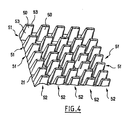
- the housing 20 advantageously comprises, on the outer face of its wall 21, a plurality of fins 50 which are shown diagrammatically on the figure 4.
- the fins 50 are arranged in parallel rows 51.
- the fins 50 are arranged at intervals regular, so that they constitute alignments 52 perpendicular to the rows 51.
- Each fin 50 has an elongated shape in one direction perpendicular to the plane of the rear wall 21, with a cross-sectional shape long axis oblong parallel to the rows 51.
- Each fin 50 has two opposite main plane faces 53 which converge with an angle of a few degrees towards the free end of the fin.
- the fins 50 are made more or less long.
- the fins 50 are made in the example described in one piece in aluminum with the rest of the housing, by means of a mold having a drawer which is interchangeable and which is chosen so as to achieve more or less long fins.
- each fin 50 facilitates the cleaning of the radiator with respect to known radiators comprising a plurality of truncated cones, because the flat main faces of the vanes provide a relatively important with a cleaning member moved parallel to the rows 51.
- the converter 10 is assembled with a housing electrical connection 60 fixed on the upper part of the housing of an engine electric.
- the housing 20 is positioned so as to be in the air flow of cooling generated by the motor fan.
- the junction box 60 has bolts 61 for fixing on the motor as well as connection terminals 62 connected to the motor.
- the wires 39 of the converter 10 are to be connected to these connection terminals 62.
- the housing 60 has in the upper part a window 63 allowing a user to easily access the electrical conductors 39 at the connection terminals 62 as well as the connector bar 37.
- Gaskets lined with gaskets are provided on the housing 60, known manner, for the passage of the supply and control wires of the converter 10.
- the housing 20 comprises at the front, in the embodiment described, a flange 26 provided with a plurality of fixing screws 23 for mounting on the housing of connection 60.
- a thermal insulating seal 25 is placed on the periphery of the flange 26 to constitute a thermal barrier tending to oppose the heat transfer of the connecting box 60 to the housing 20.
- This thermal barrier is particularly useful during low motor operation, that is to say when the fan driven by the shaft of the engine runs with low speed.
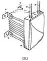
- the electronic assembly 30 allows the realization of a module that can be assembled with a connection box 60 fixed on a motor, as has just been described, or alternatively be housed in an independent housing, as it goes now be described with reference to Figure 5.
- wall mounting tabs 70 are provided on the walls side of the housing housing the electronic assembly 30.
- these lugs are provided on the rear face said housing.
- An electrical connection box 80 is fixed on the front of the housing housing the electronic assembly 30.
- Leads 81 and 82 are shown connected to the assembly electronics 30 inside the connection box 80.
- the converter housing may have fins such as those described with reference to Figure 4.
- the electronic assembly 30 with a front card, a backplane and a single intermediate card, if the number of components does not require the use of a second intermediate card.
- an intermediate module serving for example to dissipate thermal energy.
- One or more electronic power components can still be mounted on one of the intermediate cards and be thermally connected to the housing housing the electronic set.
- the motor can be replaced by a transformer, for example a transformer housed in the crankcase of an engine and whose primary and secondary are coiled on magnetic circuits similar to those of a stator and a rotor.
- a transformer for example a transformer housed in the crankcase of an engine and whose primary and secondary are coiled on magnetic circuits similar to those of a stator and a rotor.
Landscapes
- Engineering & Computer Science (AREA)
- Microelectronics & Electronic Packaging (AREA)
- Power Engineering (AREA)
- Physics & Mathematics (AREA)
- Thermal Sciences (AREA)
- Cooling Or The Like Of Electrical Apparatus (AREA)
- Control Of Electric Motors In General (AREA)
- Control Of Ac Motors In General (AREA)
- Rectifiers (AREA)
- Structures For Mounting Electric Components On Printed Circuit Boards (AREA)
Description
- la figure 1 est une vue schématique et partielle, en coupe axiale, d'un convertisseur conforme à l'invention et d'un boítier de raccordement électrique,
- la figure 2 représente isolément, en vue de côté, les cartes du convertisseur,
- la figure 3 est une vue de dessus selon la flèche III de la figure 2,
- la figure 4 est une vue partielle et schématique des ailettes de refroidissement réalisées sur la face arrière du boítier du convertisseur, et
- la figure 5 représente un convertisseur muni de pattes de fixation murale et d'un boítier de raccordement électrique indépendant.
Claims (16)
- Convertisseur pour moteur ou transformateur électrique, comportant des cartes sur lesquelles sont montés des composants, caractérisé par le fait qu'il comporte un boítier (20) dans lequel sont disposées au moins trois cartes, dont une carte arrière (32), une carte avant (31) et au moins une carte intermédiaire (33, 34) fixée à angle droit sur les cartes arrière et avant, avec des soudures (36) assurant des liaisons électriques entre les cartes, au moins un composant électronique de puissance (38) étant monté sur l'une des cartes, de préférence la carte arrière.
- Convertisseur selon la revendication 1, caractérisé par le fait que le ou les composants électroniques de puissance (38) sont reliés thermiquement à un radiateur.
- Convertisseur selon la revendication précédente, caractérisé par le fait que le radiateur est constitué au moins partiellement par le boítier (20) logeant les cartes.
- Convertisseur selon la revendication précédente, caractérisé par le fait que le radiateur est réalisé d'un seul tenant avec le reste du boítier (20), par moulage.
- Convertisseur selon l'une quelconque des revendications précédentes, caractérisé par le fait que la carte arrière (32) et au moins une partie de la ou des cartes intermédiaires (33, 34) sont noyées dans une résine électriquement isolante (40) mais thermiquement conductrice, coulée à l'intérieur du boítier.
- Convertisseur selon l'une quelconque des revendications précédentes, caractérisé par le fait que le ou les composants électroniques de puissance (38) sont montés sur la face arrière (32a) de la carte arrière (32) et sont en contact thermique avec la face intérieure (21a) de la paroi arrière (21) du boítier (20).
- Convertisseur selon la revendication précédente, caractérisé par le fait que la face intérieure (21a) de la paroi arrière (21) du boítier (20) comporte des reliefs (21b) agencés pour coopérer avec le ou les composants électroniques de puissance (38).
- Convertisseur selon l'une quelconque des revendications précédentes, caractérisé par le fait qu'il comporte une deuxième carte intermédiaire (34), parallèle à la première (33), fixée à angle droit sur les cartes arrière (32) et avant (31), avec des soudures (36) assurant des liaisons électriques entre les cartes.
- Convertisseur selon l'une quelconque des revendications précédentes, caractérisé par le fait que la carte avant (31) porte au moins un connecteur permettant d'assurer le raccordement électrique du convertisseur avec des fils électriques véhiculant des signaux de commande, et de préférence un connecteur pour l'alimentation de puissance et un connecteur pour le raccordement au moteur.
- Convertisseur selon l'une quelconque des revendications précédentes, caractérisé par le fait que la majorité des composants volumineux (58) du convertisseur sont montés sur les faces des cartes (33, 34) tournées vers le centre du boítier.
- Convertisseur selon l'une quelconque des revendications précédentes, caractérisé par le fait que l'une au moins des cartes avant, arrière et intermédiaire (s) comporte une fente et une autre desdites cartes avant, arrière et intermédiaire (s) comporte une languette (35) agencée pour s'engager dans cette fente.
- Convertisseur selon l'une quelconque des revendications précédentes, caractérisé par le fait que le radiateur comporte sur au moins une face des ailettes (50) se présentant sous la forme de nervures parallèles discontinues, créant des alignements d'ailettes dans deux directions perpendiculaires entre elles, l'air pouvant s'écouler entre les ailettes dans chacune de ces deux directions.
- Convertisseur selon la revendication précédente, caractérisé par le fait que chaque ailette (50) présente en section transversale une forme oblongue, avec des faces planes principales opposées (53) convergeant vers son sommet.
- Moteur électrique, caractérisé par le fait qu'il comporte un boítier de raccordement électrique (60) fixé sur le carter du moteur et un convertisseur tel que défini dans l'une quelconque des revendications précédentes.
- Moteur électrique selon la revendication précédente, caractérisé par le fait qu'il comporte un joint isolant thermique (25) entre le boítier du convertisseur et le boítier de raccordement (60).
- Procédé de fabrication d'un boítier de convertisseur tel que défini dans la revendication 12, caractérisé par le fait que l'on utilise un moule comportant un ou plusieurs tiroirs interchangeables et choisis selon la longueur à donner aux ailettes (50).
Applications Claiming Priority (2)
| Application Number | Priority Date | Filing Date | Title |
|---|---|---|---|
| FR0001747A FR2805120B1 (fr) | 2000-02-11 | 2000-02-11 | Convertisseur pour machine electrique |
| FR0001747 | 2000-02-11 |
Publications (2)
| Publication Number | Publication Date |
|---|---|
| EP1124408A1 EP1124408A1 (fr) | 2001-08-16 |
| EP1124408B1 true EP1124408B1 (fr) | 2005-07-06 |
Family
ID=8846931
Family Applications (1)
| Application Number | Title | Priority Date | Filing Date |
|---|---|---|---|
| EP01400342A Expired - Lifetime EP1124408B1 (fr) | 2000-02-11 | 2001-02-09 | Convertisseur pour machine électrique |
Country Status (4)
| Country | Link |
|---|---|
| EP (1) | EP1124408B1 (fr) |
| AT (1) | ATE299336T1 (fr) |
| DE (1) | DE60111786T2 (fr) |
| FR (1) | FR2805120B1 (fr) |
Families Citing this family (1)
| Publication number | Priority date | Publication date | Assignee | Title |
|---|---|---|---|---|
| FR3062275B1 (fr) * | 2017-01-20 | 2019-06-07 | Moteurs Leroy-Somer | Ensemble comportant un dispositif electronique, notamment variateur de vitesse ou regulateur d'alternateur et deux ensembles d'elements de formes differentes pour la fixation du dispositif |
Family Cites Families (4)
| Publication number | Priority date | Publication date | Assignee | Title |
|---|---|---|---|---|
| FR1289102A (fr) * | 1961-05-09 | 1962-03-30 | Haloid Xerox Inc | éléments de panneaux pour circuits électriques servant à fabriquer des appareils électriques et assemblage modulaire de circuits imprimés formés à partir desditséléments de panneaux |
| DE2146893C3 (de) * | 1971-09-20 | 1974-02-07 | Siemens Ag, 1000 Berlin U. 8000 Muenchen | Kollektorloser Gleichstrommotor mit einer durch Hall generatoren gesteuerten, aus Halbleiterschaltelementen aufgebauten Kommutierungseinrichtung |
| JPH07298555A (ja) * | 1994-02-18 | 1995-11-10 | Fuji Electric Co Ltd | サーボモータ |
| JP3513338B2 (ja) * | 1996-10-09 | 2004-03-31 | 三菱電機株式会社 | 可変速電動機 |
-
2000
- 2000-02-11 FR FR0001747A patent/FR2805120B1/fr not_active Expired - Fee Related
-
2001
- 2001-02-09 AT AT01400342T patent/ATE299336T1/de not_active IP Right Cessation
- 2001-02-09 EP EP01400342A patent/EP1124408B1/fr not_active Expired - Lifetime
- 2001-02-09 DE DE60111786T patent/DE60111786T2/de not_active Expired - Fee Related
Also Published As
| Publication number | Publication date |
|---|---|
| DE60111786T2 (de) | 2006-06-01 |
| EP1124408A1 (fr) | 2001-08-16 |
| DE60111786D1 (de) | 2005-08-11 |
| FR2805120A1 (fr) | 2001-08-17 |
| ATE299336T1 (de) | 2005-07-15 |
| FR2805120B1 (fr) | 2003-07-04 |
Similar Documents
| Publication | Publication Date | Title |
|---|---|---|
| EP1124307B1 (fr) | Convertisseur modulaire | |
| EP1062852B1 (fr) | Element de refroidissement pour dispositif electronique de puissance et dispositif electronique de puissance comprenant un tel element | |
| EP3044858B1 (fr) | Ensemble electronique pour machine electrique tournante pour vehicule automobile | |
| EP3044856B1 (fr) | Capot de protection pour machine electrique tournante pour vehicule automobile | |
| EP3176918B1 (fr) | Architecture electronique destinee a alimenter une machine electrique pour vehicule automobile | |
| FR2955432A1 (fr) | Machine dynamoelectrique a dispositif de commande integre | |
| EP3383153A1 (fr) | Dispositif de dissipation de chaleur d'un dispositif electronique | |
| EP3729612B1 (fr) | Systeme de controle d'une machine electrique tournante | |
| EP3177123A1 (fr) | Support d'une carte electronique, ensemble d'une carte electronique et d'un tel support, convertisseur de tension le comprenant et machine electrique pour vehicule automobile le comprenant | |
| EP2913910B1 (fr) | Machine électrique tournante pour véhicule automobile comprenant un ensemble électronique | |
| EP2936954B1 (fr) | Dispositif de ventilation pour installation de ventilation, chauffage et/ou climatisation | |
| EP2936955A1 (fr) | Dispositif de refroidissement pour carte de circuit imprime | |
| EP3989278A2 (fr) | Ensemble de modules de puissance à semi-conducteurs | |
| EP1058369B1 (fr) | Porte-balais à composant de commande pour alternateur de véhicule automobile | |
| FR2805120A1 (fr) | Convertisseur pour machine electrique | |
| FR3091063A1 (fr) | Module électronique de puissance pour moteur électrique intelligent | |
| FR2756676A1 (fr) | Moteur a vitesse variable et carcasse pour un tel moteur | |
| EP0743740B1 (fr) | Alternateur, notamment pour véhicule automobile, comportant un agencement de diodes de redressement | |
| EP3177122A1 (fr) | Support d'une unite electronique, dispositif electrique le comprenant et machine electrique comprenant ledit dispositif electrique | |
| EP1371113B1 (fr) | Connecteur de puissance pour circuit imprime | |
| EP4679955A1 (fr) | Dispositif de charge embarqué et moyens de refroidissement d'un module de puissance de ce dispositif de charge embarqué | |
| WO2025186333A1 (fr) | Dispositif de connexion électrique de deux stators de moteur électrique à flux axial | |
| FR2524246A1 (fr) | Systeme d'interconnexion thermique | |
| FR3010591A1 (fr) | Combinaison d'un bloc de puissance et d'un bloc de filtrage pour machine electrique tournante pour vehicule automobile | |
| FR3131080A1 (fr) | Module de puissance avec surmoulage et systeme electrique comprenant un tel module de puissance |
Legal Events
| Date | Code | Title | Description |
|---|---|---|---|
| PUAI | Public reference made under article 153(3) epc to a published international application that has entered the european phase |
Free format text: ORIGINAL CODE: 0009012 |
|
| AK | Designated contracting states |
Kind code of ref document: A1 Designated state(s): AT BE CH CY DE DK ES FI FR GB GR IE IT LI LU MC NL PT SE TR |
|
| AX | Request for extension of the european patent |
Free format text: AL;LT;LV;MK;RO;SI |
|
| 17P | Request for examination filed |
Effective date: 20011006 |
|
| AKX | Designation fees paid |
Free format text: AT BE CH CY DE DK ES FI FR GB GR IE IT LI LU MC NL PT SE TR |
|
| GRAP | Despatch of communication of intention to grant a patent |
Free format text: ORIGINAL CODE: EPIDOSNIGR1 |
|
| GRAS | Grant fee paid |
Free format text: ORIGINAL CODE: EPIDOSNIGR3 |
|
| GRAA | (expected) grant |
Free format text: ORIGINAL CODE: 0009210 |
|
| AK | Designated contracting states |
Kind code of ref document: B1 Designated state(s): AT BE CH CY DE DK ES FI FR GB GR IE IT LI LU MC NL PT SE TR |
|
| PG25 | Lapsed in a contracting state [announced via postgrant information from national office to epo] |
Ref country code: FI Free format text: LAPSE BECAUSE OF FAILURE TO SUBMIT A TRANSLATION OF THE DESCRIPTION OR TO PAY THE FEE WITHIN THE PRESCRIBED TIME-LIMIT Effective date: 20050706 Ref country code: AT Free format text: LAPSE BECAUSE OF FAILURE TO SUBMIT A TRANSLATION OF THE DESCRIPTION OR TO PAY THE FEE WITHIN THE PRESCRIBED TIME-LIMIT Effective date: 20050706 Ref country code: NL Free format text: LAPSE BECAUSE OF FAILURE TO SUBMIT A TRANSLATION OF THE DESCRIPTION OR TO PAY THE FEE WITHIN THE PRESCRIBED TIME-LIMIT Effective date: 20050706 Ref country code: IE Free format text: LAPSE BECAUSE OF FAILURE TO SUBMIT A TRANSLATION OF THE DESCRIPTION OR TO PAY THE FEE WITHIN THE PRESCRIBED TIME-LIMIT Effective date: 20050706 |
|
| REG | Reference to a national code |
Ref country code: GB Ref legal event code: FG4D Free format text: NOT ENGLISH |
|
| REG | Reference to a national code |
Ref country code: CH Ref legal event code: EP |
|
| REG | Reference to a national code |
Ref country code: IE Ref legal event code: FG4D Free format text: LANGUAGE OF EP DOCUMENT: FRENCH |
|
| REF | Corresponds to: |
Ref document number: 60111786 Country of ref document: DE Date of ref document: 20050811 Kind code of ref document: P |
|
| GBT | Gb: translation of ep patent filed (gb section 77(6)(a)/1977) |
Effective date: 20050902 |
|
| PG25 | Lapsed in a contracting state [announced via postgrant information from national office to epo] |
Ref country code: SE Free format text: LAPSE BECAUSE OF FAILURE TO SUBMIT A TRANSLATION OF THE DESCRIPTION OR TO PAY THE FEE WITHIN THE PRESCRIBED TIME-LIMIT Effective date: 20051006 Ref country code: GR Free format text: LAPSE BECAUSE OF FAILURE TO SUBMIT A TRANSLATION OF THE DESCRIPTION OR TO PAY THE FEE WITHIN THE PRESCRIBED TIME-LIMIT Effective date: 20051006 Ref country code: DK Free format text: LAPSE BECAUSE OF FAILURE TO SUBMIT A TRANSLATION OF THE DESCRIPTION OR TO PAY THE FEE WITHIN THE PRESCRIBED TIME-LIMIT Effective date: 20051006 |
|
| PG25 | Lapsed in a contracting state [announced via postgrant information from national office to epo] |
Ref country code: PT Free format text: LAPSE BECAUSE OF FAILURE TO SUBMIT A TRANSLATION OF THE DESCRIPTION OR TO PAY THE FEE WITHIN THE PRESCRIBED TIME-LIMIT Effective date: 20051212 |
|
| NLV1 | Nl: lapsed or annulled due to failure to fulfill the requirements of art. 29p and 29m of the patents act | ||
| REG | Reference to a national code |
Ref country code: IE Ref legal event code: FD4D |
|
| PG25 | Lapsed in a contracting state [announced via postgrant information from national office to epo] |
Ref country code: LI Free format text: LAPSE BECAUSE OF NON-PAYMENT OF DUE FEES Effective date: 20060228 Ref country code: CH Free format text: LAPSE BECAUSE OF NON-PAYMENT OF DUE FEES Effective date: 20060228 Ref country code: LU Free format text: LAPSE BECAUSE OF NON-PAYMENT OF DUE FEES Effective date: 20060228 Ref country code: BE Free format text: LAPSE BECAUSE OF NON-PAYMENT OF DUE FEES Effective date: 20060228 Ref country code: MC Free format text: LAPSE BECAUSE OF NON-PAYMENT OF DUE FEES Effective date: 20060228 |
|
| PLBE | No opposition filed within time limit |
Free format text: ORIGINAL CODE: 0009261 |
|
| STAA | Information on the status of an ep patent application or granted ep patent |
Free format text: STATUS: NO OPPOSITION FILED WITHIN TIME LIMIT |
|
| 26N | No opposition filed |
Effective date: 20060407 |
|
| REG | Reference to a national code |
Ref country code: CH Ref legal event code: PL |
|
| BERE | Be: lapsed |
Owner name: MOTEURS LEROY-SOMER Effective date: 20060228 |
|
| PG25 | Lapsed in a contracting state [announced via postgrant information from national office to epo] |
Ref country code: TR Free format text: LAPSE BECAUSE OF FAILURE TO SUBMIT A TRANSLATION OF THE DESCRIPTION OR TO PAY THE FEE WITHIN THE PRESCRIBED TIME-LIMIT Effective date: 20050706 |
|
| PG25 | Lapsed in a contracting state [announced via postgrant information from national office to epo] |
Ref country code: CY Free format text: LAPSE BECAUSE OF FAILURE TO SUBMIT A TRANSLATION OF THE DESCRIPTION OR TO PAY THE FEE WITHIN THE PRESCRIBED TIME-LIMIT Effective date: 20050706 |
|
| PG25 | Lapsed in a contracting state [announced via postgrant information from national office to epo] |
Ref country code: ES Free format text: LAPSE BECAUSE OF NON-PAYMENT OF DUE FEES Effective date: 20060228 |
|
| PGFP | Annual fee paid to national office [announced via postgrant information from national office to epo] |
Ref country code: GB Payment date: 20090119 Year of fee payment: 9 |
|
| PGFP | Annual fee paid to national office [announced via postgrant information from national office to epo] |
Ref country code: DE Payment date: 20090424 Year of fee payment: 9 Ref country code: IT Payment date: 20090225 Year of fee payment: 9 |
|
| PGFP | Annual fee paid to national office [announced via postgrant information from national office to epo] |
Ref country code: FR Payment date: 20090128 Year of fee payment: 9 |
|
| GBPC | Gb: european patent ceased through non-payment of renewal fee |
Effective date: 20100209 |
|
| REG | Reference to a national code |
Ref country code: FR Ref legal event code: ST Effective date: 20101029 |
|
| PG25 | Lapsed in a contracting state [announced via postgrant information from national office to epo] |
Ref country code: FR Free format text: LAPSE BECAUSE OF NON-PAYMENT OF DUE FEES Effective date: 20100301 |
|
| PG25 | Lapsed in a contracting state [announced via postgrant information from national office to epo] |
Ref country code: DE Free format text: LAPSE BECAUSE OF NON-PAYMENT OF DUE FEES Effective date: 20100901 |
|
| PG25 | Lapsed in a contracting state [announced via postgrant information from national office to epo] |
Ref country code: GB Free format text: LAPSE BECAUSE OF NON-PAYMENT OF DUE FEES Effective date: 20100209 Ref country code: IT Free format text: LAPSE BECAUSE OF NON-PAYMENT OF DUE FEES Effective date: 20100209 |