EP1123903A2 - Electrostatic batch preheater - Google Patents
Electrostatic batch preheater Download PDFInfo
- Publication number
- EP1123903A2 EP1123903A2 EP01300340A EP01300340A EP1123903A2 EP 1123903 A2 EP1123903 A2 EP 1123903A2 EP 01300340 A EP01300340 A EP 01300340A EP 01300340 A EP01300340 A EP 01300340A EP 1123903 A2 EP1123903 A2 EP 1123903A2
- Authority
- EP
- European Patent Office
- Prior art keywords
- batch material
- batch
- tunnel
- gases
- glass
- Prior art date
- Legal status (The legal status is an assumption and is not a legal conclusion. Google has not performed a legal analysis and makes no representation as to the accuracy of the status listed.)
- Withdrawn
Links
- 239000007789 gas Substances 0.000 claims abstract description 136
- 239000000463 material Substances 0.000 claims abstract description 129
- 238000000034 method Methods 0.000 claims abstract description 37
- 239000011521 glass Substances 0.000 claims abstract description 36
- 150000002500 ions Chemical class 0.000 claims abstract description 36
- 239000006066 glass batch Substances 0.000 claims abstract description 19
- 239000007787 solid Substances 0.000 claims abstract description 13
- 238000002844 melting Methods 0.000 claims abstract description 12
- 230000008018 melting Effects 0.000 claims abstract description 11
- 239000000203 mixture Substances 0.000 claims abstract description 11
- 239000006063 cullet Substances 0.000 claims abstract description 10
- 239000002994 raw material Substances 0.000 claims abstract description 9
- 238000010438 heat treatment Methods 0.000 claims abstract description 6
- 239000002245 particle Substances 0.000 claims abstract description 6
- 239000003344 environmental pollutant Substances 0.000 claims description 25
- 231100000719 pollutant Toxicity 0.000 claims description 25
- CDBYLPFSWZWCQE-UHFFFAOYSA-L Sodium Carbonate Chemical group [Na+].[Na+].[O-]C([O-])=O CDBYLPFSWZWCQE-UHFFFAOYSA-L 0.000 claims description 20
- 239000000470 constituent Substances 0.000 claims description 16
- 239000013618 particulate matter Substances 0.000 claims description 11
- 229910000029 sodium carbonate Inorganic materials 0.000 claims description 10
- 235000017550 sodium carbonate Nutrition 0.000 claims description 9
- 235000019738 Limestone Nutrition 0.000 claims description 8
- 239000006028 limestone Substances 0.000 claims description 8
- 230000005484 gravity Effects 0.000 claims description 7
- 230000009471 action Effects 0.000 claims description 5
- 238000006243 chemical reaction Methods 0.000 claims description 5
- 239000013590 bulk material Substances 0.000 claims description 3
- RAHZWNYVWXNFOC-UHFFFAOYSA-N Sulphur dioxide Chemical group O=S=O RAHZWNYVWXNFOC-UHFFFAOYSA-N 0.000 claims 4
- FGUUSXIOTUKUDN-IBGZPJMESA-N C1(=CC=CC=C1)N1C2=C(NC([C@H](C1)NC=1OC(=NN=1)C1=CC=CC=C1)=O)C=CC=C2 Chemical compound C1(=CC=CC=C1)N1C2=C(NC([C@H](C1)NC=1OC(=NN=1)C1=CC=CC=C1)=O)C=CC=C2 FGUUSXIOTUKUDN-IBGZPJMESA-N 0.000 claims 2
- KRHYYFGTRYWZRS-UHFFFAOYSA-N Fluorane Chemical group F KRHYYFGTRYWZRS-UHFFFAOYSA-N 0.000 claims 2
- VEXZGXHMUGYJMC-UHFFFAOYSA-N Hydrochloric acid Chemical group Cl VEXZGXHMUGYJMC-UHFFFAOYSA-N 0.000 claims 2
- 229910000041 hydrogen chloride Inorganic materials 0.000 claims 2
- IXCSERBJSXMMFS-UHFFFAOYSA-N hydrogen chloride Substances Cl.Cl IXCSERBJSXMMFS-UHFFFAOYSA-N 0.000 claims 2
- 229910000040 hydrogen fluoride Inorganic materials 0.000 claims 2
- 235000010269 sulphur dioxide Nutrition 0.000 claims 2
- 239000004291 sulphur dioxide Substances 0.000 claims 2
- 239000000428 dust Substances 0.000 description 18
- 239000000446 fuel Substances 0.000 description 14
- 230000008569 process Effects 0.000 description 11
- 238000012546 transfer Methods 0.000 description 11
- 238000013461 design Methods 0.000 description 10
- 238000002485 combustion reaction Methods 0.000 description 9
- 230000008901 benefit Effects 0.000 description 8
- 230000009467 reduction Effects 0.000 description 7
- 239000002253 acid Substances 0.000 description 6
- 230000000694 effects Effects 0.000 description 6
- QVGXLLKOCUKJST-UHFFFAOYSA-N atomic oxygen Chemical compound [O] QVGXLLKOCUKJST-UHFFFAOYSA-N 0.000 description 5
- 239000012717 electrostatic precipitator Substances 0.000 description 5
- 239000001301 oxygen Substances 0.000 description 5
- 229910052760 oxygen Inorganic materials 0.000 description 5
- 238000010923 batch production Methods 0.000 description 4
- 230000005684 electric field Effects 0.000 description 4
- 238000005816 glass manufacturing process Methods 0.000 description 4
- VYPSYNLAJGMNEJ-UHFFFAOYSA-N Silicium dioxide Chemical compound O=[Si]=O VYPSYNLAJGMNEJ-UHFFFAOYSA-N 0.000 description 3
- 230000033228 biological regulation Effects 0.000 description 3
- 239000007795 chemical reaction product Substances 0.000 description 3
- 230000007423 decrease Effects 0.000 description 3
- 238000005367 electrostatic precipitation Methods 0.000 description 3
- 230000006870 function Effects 0.000 description 3
- 238000009434 installation Methods 0.000 description 3
- 239000012212 insulator Substances 0.000 description 3
- 239000006060 molten glass Substances 0.000 description 3
- 239000000126 substance Substances 0.000 description 3
- 239000002918 waste heat Substances 0.000 description 3
- VTYYLEPIZMXCLO-UHFFFAOYSA-L Calcium carbonate Chemical compound [Ca+2].[O-]C([O-])=O VTYYLEPIZMXCLO-UHFFFAOYSA-L 0.000 description 2
- DGAQECJNVWCQMB-PUAWFVPOSA-M Ilexoside XXIX Chemical compound C[C@@H]1CC[C@@]2(CC[C@@]3(C(=CC[C@H]4[C@]3(CC[C@@H]5[C@@]4(CC[C@@H](C5(C)C)OS(=O)(=O)[O-])C)C)[C@@H]2[C@]1(C)O)C)C(=O)O[C@H]6[C@@H]([C@H]([C@@H]([C@H](O6)CO)O)O)O.[Na+] DGAQECJNVWCQMB-PUAWFVPOSA-M 0.000 description 2
- 238000005267 amalgamation Methods 0.000 description 2
- 230000009286 beneficial effect Effects 0.000 description 2
- 230000015572 biosynthetic process Effects 0.000 description 2
- 239000011449 brick Substances 0.000 description 2
- 230000003247 decreasing effect Effects 0.000 description 2
- 230000001419 dependent effect Effects 0.000 description 2
- 238000010586 diagram Methods 0.000 description 2
- 238000010304 firing Methods 0.000 description 2
- 239000002803 fossil fuel Substances 0.000 description 2
- 239000004615 ingredient Substances 0.000 description 2
- 230000007257 malfunction Effects 0.000 description 2
- 238000004519 manufacturing process Methods 0.000 description 2
- 229910052751 metal Inorganic materials 0.000 description 2
- 239000002184 metal Substances 0.000 description 2
- 238000001556 precipitation Methods 0.000 description 2
- 230000001172 regenerating effect Effects 0.000 description 2
- 229910052708 sodium Inorganic materials 0.000 description 2
- 239000011734 sodium Substances 0.000 description 2
- 238000005496 tempering Methods 0.000 description 2
- MYMOFIZGZYHOMD-UHFFFAOYSA-N Dioxygen Chemical compound O=O MYMOFIZGZYHOMD-UHFFFAOYSA-N 0.000 description 1
- 206010035148 Plague Diseases 0.000 description 1
- PMZURENOXWZQFD-UHFFFAOYSA-L Sodium Sulfate Chemical compound [Na+].[Na+].[O-]S([O-])(=O)=O PMZURENOXWZQFD-UHFFFAOYSA-L 0.000 description 1
- 241000607479 Yersinia pestis Species 0.000 description 1
- 238000010521 absorption reaction Methods 0.000 description 1
- 230000002378 acidificating effect Effects 0.000 description 1
- 238000004458 analytical method Methods 0.000 description 1
- 238000013459 approach Methods 0.000 description 1
- 229910000019 calcium carbonate Inorganic materials 0.000 description 1
- 239000000919 ceramic Substances 0.000 description 1
- 239000003153 chemical reaction reagent Substances 0.000 description 1
- 238000004891 communication Methods 0.000 description 1
- 238000010276 construction Methods 0.000 description 1
- 238000007796 conventional method Methods 0.000 description 1
- 238000001816 cooling Methods 0.000 description 1
- 238000010410 dusting Methods 0.000 description 1
- 238000005516 engineering process Methods 0.000 description 1
- 239000005431 greenhouse gas Substances 0.000 description 1
- 230000006872 improvement Effects 0.000 description 1
- 230000008595 infiltration Effects 0.000 description 1
- 238000001764 infiltration Methods 0.000 description 1
- 206010022000 influenza Diseases 0.000 description 1
- 230000010354 integration Effects 0.000 description 1
- 239000007788 liquid Substances 0.000 description 1
- 230000007246 mechanism Effects 0.000 description 1
- 239000000155 melt Substances 0.000 description 1
- 238000010309 melting process Methods 0.000 description 1
- 230000008450 motivation Effects 0.000 description 1
- 239000000615 nonconductor Substances 0.000 description 1
- 238000013021 overheating Methods 0.000 description 1
- 238000010791 quenching Methods 0.000 description 1
- 238000011084 recovery Methods 0.000 description 1
- 230000008439 repair process Effects 0.000 description 1
- 239000004576 sand Substances 0.000 description 1
- 230000009528 severe injury Effects 0.000 description 1
- 239000000377 silicon dioxide Substances 0.000 description 1
- 238000012384 transportation and delivery Methods 0.000 description 1
- 238000009827 uniform distribution Methods 0.000 description 1
- XLYOFNOQVPJJNP-UHFFFAOYSA-N water Substances O XLYOFNOQVPJJNP-UHFFFAOYSA-N 0.000 description 1
Images




Classifications
-
- C—CHEMISTRY; METALLURGY
- C03—GLASS; MINERAL OR SLAG WOOL
- C03B—MANUFACTURE, SHAPING, OR SUPPLEMENTARY PROCESSES
- C03B3/00—Charging the melting furnaces
- C03B3/02—Charging the melting furnaces combined with preheating, premelting or pretreating the glass-making ingredients, pellets or cullet
- C03B3/023—Preheating
-
- C—CHEMISTRY; METALLURGY
- C03—GLASS; MINERAL OR SLAG WOOL
- C03B—MANUFACTURE, SHAPING, OR SUPPLEMENTARY PROCESSES
- C03B3/00—Charging the melting furnaces
-
- Y—GENERAL TAGGING OF NEW TECHNOLOGICAL DEVELOPMENTS; GENERAL TAGGING OF CROSS-SECTIONAL TECHNOLOGIES SPANNING OVER SEVERAL SECTIONS OF THE IPC; TECHNICAL SUBJECTS COVERED BY FORMER USPC CROSS-REFERENCE ART COLLECTIONS [XRACs] AND DIGESTS
- Y02—TECHNOLOGIES OR APPLICATIONS FOR MITIGATION OR ADAPTATION AGAINST CLIMATE CHANGE
- Y02P—CLIMATE CHANGE MITIGATION TECHNOLOGIES IN THE PRODUCTION OR PROCESSING OF GOODS
- Y02P40/00—Technologies relating to the processing of minerals
- Y02P40/50—Glass production, e.g. reusing waste heat during processing or shaping
Definitions
- the invention relates to a method and apparatus for preheating raw materials for glass production using waste heat from the glass melting process.
- the invention uses electrostatic forces to improve the performance of conventional methods of preheating glass batch materials. Additionally, the electrostatic forces act to remove fine particulate matter from the glass furnace exhaust gases, thus achieving simultaneous pollution emission reduction.
- Glass is made by heating and melting a mixture of solid raw materials to a liquid state.
- the melting is done inside of a furnace and necessarily requires substantial amounts of heat.
- this heat is generated by the combustion of fossil fuels with the exhaust gases from the combustion leaving the furnace.
- Exhaust gas temperatures immediately after the furnace are quite high, typically 1300°C-1450°C.
- Combustion air preheaters are normally included which recover some of the heat in these gases. Even so, gas temperatures at the discharge to atmosphere are quite high, thus substantial amounts of heat are wasted.
- the cost of fuel for the furnace is a major component in the cost of making glass.
- the raw materials for glass are typically called batch.
- the word frit generally refers to an assemblage of various pulverous materials including silica sand, limestone, soda ash, salt cake, and a variety of other minor ingredients. The material and mixture ratios are carefully chosen to produce glass of the desired properties and quality. Generally these materials are prepared in a finely divided form to promote their melting rates. Sizes are typically 100 to 200 ⁇ m diameter with a maximum size of 1 mm.
- recycled glass either from the factory or from external sources, is used as a raw material. This recycled glass is called cullet. For ease of handling cullet is generally crushed to sizes less than 50 mm before use in the glass furnace. Sometimes, cullet is pulverised to sizes similar to the other raw materials.
- the word batch will be used to mean frit alone, cullet alone, or a mixture of frit and cullet, the cullet being either crushed or pulverised.
- US Patent Specification No. 4 696 690 described a device in which furnace exhaust gases are passed through "flow ducts" inside a batch bunker.
- the upper half of the flow ducts are formed by equal sided angle sections arranged to form a roof like structure inside the bunker. The angles provide an open bottom and the batch itself forms the bottom half of the flow duct, due to its angle of repose under the roof.
- Batch is introduced to the bunker through its open top.
- the batch is moved downward by gravity, thus providing continuously renewed surfaces in the flow ducts that are exposed to the furnace exhaust gases. Heat is transferred to the batch primarily because of the direct contact with the hot gases.
- the flow ducts are arranged in horizontal banks, with the furnace gas divided to flow through the ducts of a given bank in parallel. Multiple banks of flow ducts are provided one above another and internal tunnels are provided to direct the flow successively from the lower banks to the upper banks. The result is to achieve a countercurrent flow of hot gases with the downward moving batch in the bunker. Batch is fed out of the device through a nozzle as controlled by a conventional device such as a vibratory, screw, or other mechanical type feeder.
- One aspect of the invention in which these objectives or benefits can generally be achieved is directed to a method for heating glass batch materials before use in a glass melting furnace, the glass batch material comprising solid particle raw materials or cullet, or a mixture of the two, the method comprising the steps of:
- the top portion of the tunnel comprises electrically conducted plates forming a roof within the bulk material and in contact with the batch material.
- the roof is arranged so that the bottom portion of the tunnel comprises batch material residing at its gravitational angel of repose beneath the roof.
- unheated batch material can be supplied to the top of the hopper.
- heated batch material can be removed from the bottom of the hopper so that the batch material moves through the hopper by action of gravity.
- the tunnel is advantageously of cylindrical shape and preferably is generally horizontally disposed within the hopper.
- Another aspect of the present invention is directed to an apparatus for carrying out the foregoing method.
- fine dust pollutants in the gases are removed from the gases by electrostatic precipitation onto the inside of the flow tunnels, including precipitation directly onto the batch surface, and are subsequently removed from the hopper along with the batch material.
- gaseous pollutants introduced with the gases are chemically reacted with a constituent of the batch material to form a solid reaction product that is removed from the hopper with the batch material.
- a plurality of such tunnels is provided, the gases are first introduced to the tunnels near the bottom of the hopper and are finally removed from tunnels near the top of the hopper. Gases are directed to flow successively through the tunnels, or banks of tunnels, from the bottom to the top of the hopper. The batch is introduced at the top and removed from the bottom of the hopper so that the gas and batch flow in direction generally countercurrent to each other.
- the invention can be advantageously used to preheat the batch using heat from the exhaust gases.
- preheating these materials before they are introduced to the furnace the amount of fuel required for heating and melting them in the furnace can be reduced.
- This fuel reduction can represent a substantial economic benefit to the glass making process and also reduces the emission of the so-called green house gases (such as NOx and CO 2 ) simply because less fuel is burned.
- pollutant emissions such as fine dust, SO 2 , HCl, and HF can be reduced with high efficiency to satisfy stringent regulations.
- SO 2 , HCl, and HF emissions can be reduced because most glass batch contains substantial amounts of material which is chemically reactive with these acid gases, specifically soda ash (Na 2 CO 3 ) and limestone (CaCO 3 ).
- Fossil fuel fired glass furnaces are of several different designs. When air is combusted with fuel, the air is typically preheated in regenerative or recuperative heat exchangers, utilising some of the waste heat exiting the furnace. As well, nominally pure oxygen can also be used for combustion, in which case no waste heat recovery equipment is typically involved.
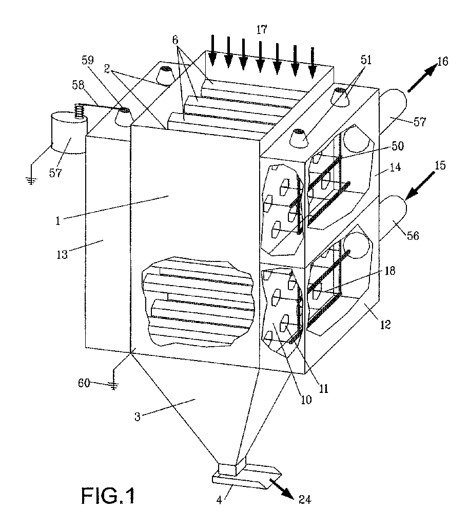
- FIG. 1 is a perspective cut-away view of the device.
- a bulk quantity of glass batch material (not shown in Figure 1) fills a hopper 1 .
- the hopper will generally have a square or rectangular plan view cross section 2 .
- a second pyramid shaped discharge hopper 3 allows for material discharge 24 via feeder 4 to produce a substantially uniform flow of the material in the hopper.
- Such technology for achieving " mass flow" in hoppers is well known in the art.
- Batch material is uniformly supplied at 17 across the top of the hopper by conventional silo and material handling means. Generally, the hopper 1 is maintained in a full condition.
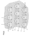
- FIG. 2 is a cross sectional view of the interior of hopper 1 .
- Horizontal open bottom tubes 6 form the open tunnels 22 in the bulk quantity of batch material 20.
- Batch material fills below the tube at its natural angle of repose to form a surface 7 , thus the batch material itself completes the tube circumference.
- Figure 2 shows a hexagonal tube design, with the batch material forming two flat surfaces 7 at its bottom.
- the two top 8 and two side 9 surfaces of the hexagon are typically metallic plates.
- the material angle of repose is typically about 30° from the horizontal, so the use of hexagonal geometry maintains good symmetry of the entire flow tunnel. The symmetry is important for the uniform generation of corona discharge within the tunnels as will be explained later.
- Other tube geometries could also be used effectively, such as circular cylindrical.
- the tubes are extended to a wall 10 of the main hopper and a suitable hole 11 is cut into the hopper wall to allow communication of each tunnel interior with the outside of the hopper for flow of gases. Both ends of the tubes are so constructed, thus allowing a free passage for gas flow through the entire width of hopper 1 . Many such rows of tubes are typically provided.
- Plenum structures 12, 13, and 14 are provided exterior to the hopper and they allow for the desired routing of gas flow through the device.
- Hot gases 15 from the glass furnace are directed to the inlet plenum 12 via inlet pipe 56 .
- This inlet plenum 12 encloses several rows of the flow tunnels. This assemblage of rows of tunnels is termed a bank of tunnels.
- the plenum design is made so that the gases divide approximately equally and flow through all the tunnels of a given bank enclosed by the plenum.
- a second plenum 13 is provided to gather the gases and then direct them to another bank of tunnels immediately above the first. After passage through this second bank of tunnels, the gases collect in the outlet plenum 14. Cooled gases 16 are then discharged from the device via outlet duct 57 .
- a fundamental limitation of the prior art is the fact that any batch material supplied to the hopper will contain a certain amount of fine dust. When this fine dust is contacted with the flowing gases in the tunnels, the dust is entrained in gas flow and carried out of the hopper. Gases 16 exiting the device show a substantial loading of dust carried over from the batch in the device. This carryover is not acceptable, as its discharge to atmosphere constitutes a pollution emission.
- the mass transfer rate of pollutant gases to contact the surface of the batch material is low for similar reasons, thus the removal efficiency of gaseous pollutants is generally less than to achieve outlet levels less than those mandated by governmental authorities.
- Each of the tunnels is provided with a discharge electrode 18 axially aligned and centrally located within the tunnel.
- a simple wire is shown, but other designs incorporating sharp points for generation of corona may be used.
- the wires 18 for a given bank of tunnels are connected together at either end by brackets 50 and electrical insulators 51 support the brackets. Such insulators are typically of ceramic construction. Similar brackets (not shown) are provided in plenum 13 . The wires and brackets are thus electrically isolated from the plenums 12, 13, 14 and hopper 1 .
- brackets and brackets are well known to those skilled in the art of electrostatic precipitation.
- a high voltage DC power supply 57 is connected 58 to the brackets via the bracket extension 59 through the support insulator.
- One power supply can be used for the entire unit, or alternatively, separate power supplies can be supplied for each bank of tunnels.
- the hopper is electrically grounded 60 .
- the electrically conducive plates 8 and 9 of each tube are connected to the hopper wall 10 and thus are also electrically grounded.
- the high voltage DC power supply 57 serves to apply a high voltage to the discharge electrodes 18 .
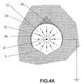
- Application of high voltage of sufficient magnitude to the discharge electrode 18 will produce a corona discharge 52 inside of the tunnel as depicted in Figure 2.
- the corona discharge is well known to those skilled in the art, so extensive description of the corona process is not necessary.
- the corona process produces a flow of gaseous ions from the discharge electrode towards the grounded surfaces surrounding the electrode.
- the metallic tube is electrically conductive and is grounded, so it provides an easy path for the ions to flow to ground.
- the corona discharge ion flow can also be directed towards the batch material surfaces 7 of the tunnel. These ions 53 then flow through the bulk of the batch material into the metal tubes and then to ground as depicted in Figure 3A. This can occur provided the batch material is of sufficiently low electrical resistivity, as is the case of Figure 3A. However, if the batch material were of high electrical resistivity, as depicted in Figure 3B, electrical current could not flow through the batch. The ions from the corona would then produce a build up of electrostatic charges 54 on the batch surface. Since a negative corona discharge polarity is normally used in electrostatic precipitation, the example here uses negative polarity. The same operation and analysis would also apply for positive polarity. This charge build-up would then prevent the continued flow of ions to the batch.
- the electrostatic charge build-up 54 would quench the corona discharge, and the flow of corona gaseous ions would stop. This would produce a quiescent region 55 in the tunnel that would be free of corona discharge ion flow. However, corona discharge ion flow would continue in the regions adjacent to the electrically conductive plates 8 and 9 as depicted in Figure 3B. If the resistivity of batch material were very high, such charge build-up would result in the well-known "back-corona" effect that can plague operation of electrostatic precipitators. At these very high resistivities, the charge build-up 53 is so great that a secondary corona discharge is generated from the surface of the resistive material, emitting positive ions into the gas.
- the electrostatic precipitator exhibits tremendously increased spark-over rates at reduced voltages. Precipitation performance is dramatically reduced. Generally, the limiting bulk electrical resistivity for this phenomenon is about 10 8 ⁇ -meter.
- This force 62 is directed perpendicular towards the free surface 7 of batch material and will thus act to defeat the entrainment of dust from the batch into the gas flow.
- the equation demonstrates that the cohesive force is strongly dependent upon both the resistivity of the batch material and the corona discharge ion current density.
- the batch must have sufficiently low electrical resistivity that corona current flow will pass through material to the grounded tubes. Generally, we can say that this resistivity must be below 10 8 ⁇ -meter.
- Electrical resistivity of batch is primarily a function of the chemical composition of the batch and the temperature of the batch.
- batch is a blend of several ingredients, and the resistivity is also a function of the physical disposition of the various chemical constituents in the blend.
- the primary means of electrical conductance in batch is ionic conduction through the sodium constituents of the batch which is temperature dependent.
- soda ash generally provides sufficient electrical conductivity that the resistivity remains below the critical 10 8 ⁇ -meter. In dry air, the resistivity increases monotonically with decreasing temperature and below about 200°C the resistivity would rise above the critical point.
- the resistivity curve follows the dry air curve for higher temperatures, but for temperatures below about 200°C the resistivity actually decreases with decreasing temperature.
- furnace gases typically contain high amounts of water vapour and trace amounts of acidic gases.
- Below temperatures of about 200°C acid will condense onto solid surfaces, the so-called acid dew point.
- acid dew point At first, only minute amounts of acid condense on the solid surface, but this minute surface film is enough to provide some electrical conductance. Effectively the electrical conductance mechanism switches over from ionic conduction through the sodium constituent of the batch to surface conduction through the acid film on the surface of the batch particles. Because the electrical resistivity of batch is below the limit imposed by back-corona, but still high enough to produce strong cohesive forces at the batch surface 7, entrainment of dust from the batch can be eliminated.
- the corona discharge will provide two other important functions. First, it will electrostatically charge any fine particulate matter in the furnace exhaust gases and then force them towards either the interior surfaces of the metallic tubes 8 and 9 , or the surface 7 of the batch material. This is conventional electrostatic precipitator operation. Generally, if enough collection surface area is provided, the fine particulate matter will be precipitated from the furnace gases with high efficiency.
- the gaseous ion flow in the corona discharge produces intense fine scale turbulence in the gas.
- Such turbulence has the effect of improving both heat transfer rates and mass transfer rates from the flowing gases to the batch material surface. This will have the effect of increasing the preheat temperature of the batch exiting the device and increasing the removal of gaseous pollutants from the furnace gases by chemical reaction with the batch material.
- heat and mass transfer rates are typically limited by the formation of a gas flow "boundary layer" near a solid surface. Gas velocities are low in this boundary layer, and the layer becomes the bottleneck in the heat or mass transfer processes. Heat or mass must then diffuse through the layer at a very slow rate.
- the corona-induced turbulence is especially effective at significantly reducing the thickness of this boundary layer, thus increasing transfer rates.
- the E-batch process can achieve better batch preheating and better gaseous pollutant removal in a physically smaller device.
- corona-induced turbulence is commonly known as corona wind. It results from the fact that the gaseous ions being electrostatically propelled through the gas actually create a drag on the surrounding gases and set them in motion. This effect can be optimised by suitable electrode design, for cases where still higher heat and mass transfer rates are desired.
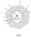
- Figure 5 shows an improved electrode design to optimise corona-induced turbulence for heat and mass transfer.
- the wire is replaced by a bar 66 of large enough diameter that little corona is produced from its surface.
- the interior cross sectional dimensions of the tube might be 6 to 12 inches.
- Such a bar then might be of 1 ⁇ 2 to 2 inch diameter.
- Sharpened needlepoints 67 are affixed to the bar at regular intervals and are pointed towards to the batch surface 7 . Spacing between adjacent needlepoints might be in the range of 1 inch to 6 inches.
- the provision of the needlepoint results in localised generation of corona discharge at the needle tip 67, with the gaseous ion flow 69 being almost entirely toward the batch surface 7 .
- the other regions 68 of the tunnel are essentially quiescent with respect to gaseous ion flow. Such an arrangement has two benefits.
- the non-uniform corona ion flow will create a corona-induced gas flow pattern 70 inside the tunnel, with gas velocity directed toward the batch surface 7 .
- Such a gas circulation will carry gases from the entire tunnel cross section towards the batch surface 7 . This will greatly improve the desired heat and mass transfer processes.
- baffles 97 can be provided to promote good flow of the batch material, as depicted in Figure 4B.
- steeply sloped baffles 97 immediately above tube 96 eliminate the possibility of stagnant batch material 98 directly on top of tube 96.
- stagnant areas can create large agglomerates of batch that can dislodge and then obstruct proper material flow through the hopper.
- the basic objective of the invention is to preheat batch material for use in a glass furnace, with simultaneous reduction of pollution emissions in the exhaust gases.
- the benefits of the E-batch process of the invention are greatest in the case of oxygen-fuel fired furnaces because:
- Glass melting furnaces operate under extreme conditions of temperature while maintaining very precise operating conditions. Exhaust gases are hot and chemically aggressive.
- the batch material consists of an amalgamation of several components of varying chemical and physical composition that are reactive, abrasive, hygroscopic and prone to dusting.
- Equipment applied to glass furnaces, especially one handling both the batch material and the exhaust gases, must be simple and reliable. This description is important because the advantage of the E-batch process, compared to the alternatives, becomes apparent when its full integration with the glass manufacturing process is understood.
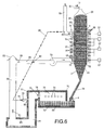
- the glass furnace 71 is a refractory brick structure enclosing a pool 72 of molten glass and a combustion space 73. Burners 74 are supplied with oxygen and fuel and produce flames inside the combustion space. Heat from the flames melts the glass 72. Molten glass exits the furnace through ports not shown in this diagram. Batch material is fed into the furnace via charging machine 4 . Many types of charging machines are commonly used, including vibratory feeders, screw feeders, reciprocating pushers, etc. Batch material is fed into the furnace at variable rates in order to maintain a constant top 95 level of molten glass 72 in the furnace. As such, feeder 4 must be capable of providing batch to the furnace at variable rates.
- preheating batch The effect of preheating batch is to reduce the firing rate of the burners in the furnace. Preheated batch requires less energy to melt than unheated batch. Reducing the firing rate of the burners reduces both the amount of oxygen and the amount of fuel required by the burner.
- Exhaust gases 75 from the combustion space exit the furnace through port 76 and enter flue channel 77 .
- These exhaust gases 75 are typically at temperatures of 1300°C-1400°C, so the flue channel must also be constructed of refractory brick material.
- Batch material typically begins to melt at temperature of about 600°C. If this melting were to occur inside the E-batch preheater, the batch would stick together and to the metal surfaces of the device, which would render the device non-operational. In order to prevent overheating of the batch, the hot gases from the furnace must be tempered before introduction to the E-batch device.
- Tempering air 78 is injected into the flue channel by fan 79 through port 80 .
- the air 78 mixes with the furnace gases 75 to produce tempered exhaust gases 81 in a lower portion of the flue channel.
- These tempered gases 81 are typically at about 550°C-600°C. Normally, this temperature is measured and the fan 79 speed controlled to maintain the desired temperature.
- cooled gases 87 exiting the E-batch module can be recirculated 95 to provide the desired gas tempering. In this way, no extra oxygen is introduced to the system and no heat is lost due to the cold air infiltration.
- Tempered exhaust gas 81 then flows through stack 82 and duct 83. These ducts and stack will be well insulated to maintain the exhaust gas temperature.
- Fan 84 is provided to overcome the back pressure developed when gases flow through the E-batch device. The passage of gases through the plurality of tunnels in the E-batch requires a certain amount of pressure, but conventional fans commonly used for this purpose can handle this. The fan speed will be controlled in order to maintain proper pressure inside the combustion space 73 of the furnace. Stable pressure in the combustion space 73 is critical to the glass manufacturing process.
- the fan can be located on the downstream side of the E-batch module. Then it will be handling cooler and cleaner gases.
- the stack 82 is provided with an emergency vent 85 and valve 86.
- the furnace exhaust gases must be quickly diverted to atmosphere.
- the glass furnace cannot be shut down or allowed to cool down, otherwise severe damage to the furnace will result.
- the vent 85 quickly opens and valve 86 closes.
- a controller will then position the flaps of emergency vent 85, in order to maintain furnace operating pressure, since fan 84 will no longer be serving this purpose.
- tempered gases 82 will discharge from fan 84 and enter inlet plenum 12 of the E-batch preheater.
- the E-batch preheater shown in Figure 6 is consistent with the previous descriptions, but with further special aspects. Several banks of tunnels are provided, in this example a total of eight. Additional intermediate plenums 13 are thus provided. Cleaned and cooled gases 87 exit the E-batch preheater from outlet plenum 14. A stack 89 discharges these gases 87 to atmosphere.
- the final bank of tunnels 88 is provided with the greatest number of tunnels. It will be beneficial to reduce the gas velocity in this final bank to assure that virtually no batch dust is entrained in the gases leaving this bank, since these gases are discharged directly to atmosphere. As well, this final bank will be provided with its own high voltage power supply, so that optimum electrostatic operation is maintained at all times.
- the E-batch module is provided with a surge hopper 90 that holds batch material above its active sections. It is important that the top level of batch 92 in the surge hopper does not fall below the uppermost tunnel 93 in the E-batch preheater.
- Batch material 17 is delivered to the top of the surge hopper by conventional material handling equipment 91 , such as bucket elevators and belt conveyors. Typically, this equipment is intermittently operated, so the capacity of reservoir must be adequate to allow for the intervals between batch deliveries. As well, the capacity of the surge hopper must be sufficient to allow for batch to be fed to the furnace by feeder 4 during any period of time required to repair a failure of material handling equipment 91.
- Hot batch from the bottom of the E-batch module lower hopper 3 flows to the furnace-charging machine 4 by a gravity chute 94. Hot batch is dry and prone to generate fugitive dust emissions, so handling of this material is to be minimised. Hopper 3 and chute 94 are sealed in a dust-tight fashion. As well, hopper 3 and chute 94 will be well insulated to maintain temperature of the preheated batch.
Landscapes
- Chemical & Material Sciences (AREA)
- Engineering & Computer Science (AREA)
- Materials Engineering (AREA)
- Organic Chemistry (AREA)
- Furnace Details (AREA)
- Glass Melting And Manufacturing (AREA)
- Treating Waste Gases (AREA)
Abstract
Description
Ji = corona current density at batch surface (Ampere / sq. meter)
Claims (32)
- A method for heating glass batch materials before use in a glass melting furnace, the glass batch material comprising solid particle raw materials or cullet, or a mixture of the two, the method comprising the steps of:a) providing a bulk quantity of glass batch material in a hopper;b) providing at least one gas flow tunnel through the bulk quantity of batch material, at least a portion of the surface of the tunnel consisting of a surface of the batch material;c) passing glass furnace exhaust gases through the tunnel;d) providing an electrically conductive electrode within the tunnel;e) providing an electrically conductive surface in contact with the batch material; andf) applying an electrical potential difference between the electrode of step d) and the surface of step e) of sufficient magnitude to produce corona discharge inside the tunnel, the corona discharge consisting of a flow of gaseous ions through the furnace gases, at least a portion of the gaseous ions flowing into the glass batch material.
- The method of claim 1 wherein the gases flowing through the tunnel are at sufficient velocity so that at least some of the batch material would be entrained in the flowing gases if the electrical potential difference of step f) were not applied.
- The method of claim 1 or claim 2 wherein the bulk electrical resistivity of the batch material is less than 108 Ω-metre.
- The method of any one of claims 1 to 3 including the additional steps of:a) removing heated batch material from the bottom of so that the batch material moves through the hopper by action of gravity.b) supplying unheated batch material to the top of the hopper
- The method of claim 4 wherein the batch material motion renewed surfaces of batch material in the tunnel.
- The method of any one of claims 1 to 5 wherein:a) the tunnel is of cylindrical shape and is generally horizontally disposed within the hopper;b) the top portion of the cylindrical tunnel consists of electrically conductive plates forming roofs within the bulk material;c) the roofs are arranged so that the bottom portion of the cylindrical tunnel consists of batch material residing at its angle of repose beneath the roofs; andd) the roofs of b) comprising the electrically conductive surface of claim 1, step e).
- The method of claim 6 wherein the cylindrical tunnel is a hexagonal cylinder with an apex of the hexagon directed upward, the electrically conductive plates forming the two top and two side portions of the hexagonal cylinder, and the batch material forming the two bottom portions of the hexagonal cylinder.
- The method of claim 6 or claim 7 wherein the top portion b) of the cylinder is a circular cylinder with a bottom section removed.
- The method of any of claims 6 to 8 wherein the discharge electrode consists of a wire, a small radiuses bar, or a bar fitted with small radiused points or edges, the discharge electrode being axially aligned and essentially centrally located within the cylinder.
- The method of any one of claims 6 to 10 comprising of a plurality of the tunnels, thus forming a bank of the tunnels, the furnace gases being divided to flow through the tunnels in parallel.
- The method of claim 10 further comprising:a) a plurality of the banks of tunnels located one above another;b) the gases being directed to flow first through the bottom-most bank, then successively through each vertically adjacent bank; andc) heated batch material is removed from the bottom of the hopper and unheated batch material is added to the top of the hopper in a substantially continuous fashion, so that the batch material moves through the hopper by action of gravity.
- The method of any one of claims 1 to 11 wherein the glass furnace exhaust gases contain particulate matter and at least a portion of the particulate matter is electrostatically precipitated from the gases onto the inside surface of the tunnel.
- The method of any one of claims 1 to 12 wherein the glass furnace exhaust gases contain a gaseous pollutant, the batch material is at least partially comprised of a constituent that is chemically reactive with the pollutant, and at least some of the gaseous pollutant is removed from the furnace exhaust gases by reaction with the batch material constituent.
- The method of claim 13 wherein the gaseous pollutant is sulphur dioxide and the batch constituent is soda ash or limestone.
- The method of claim 13 wherein the gaseous pollutant is hydrogen chloride and batch constituent is soda ash or limestone.
- The method of claim 13 wherein the gaseous pollutant is hydrogen fluoride and batch constituent is soda ash or limestone.
- An apparatus for heating glass batch materials before use in a glass melting furnace, the glass batch material consisting of solid particle raw materials or cullet, or a mixture of the two, comprising:a) a bulk quantity of glass batch material contained in a hopper;b) at least one gas flow tunnel through the bulk quantity of batch material, at least a portion of the surface of the tunnel consisting of a free surface of the batch material;c) means to pass glass furnace exhaust gases through the tunnel;d) an electrically conductive electrode within the tunnel;e) an electrically conductive surface in contact with the batch material; andf) means to apply an electrical potential difference between the electrode of step d) and the surface of step e) of sufficient magnitude to produce corona discharge inside the tunnel, the corona discharge consisting of a flow of gaseous ions through the furnace gases, at least a portion of the gaseous ions flowing into the glass batch material.
- The apparatus of claim 17 wherein the gases flowing through the tunnel are at sufficient velocity so that at least some of the batch material would be entrained in the flowing gases if the electrical potential difference of step f) were not applied.
- The apparatus of claim 17 or claim 18 wherein the bulk electrical resistivity of the batch material is less than 108 Ω-metre.
- The apparatus of any one of claims 17 to 19 further including:a) means to remove heated batch material from the bottom of the so that the batch material moves through the hopper by action of gravity; andb) means to add unheated batch material to the top of the hopper.
- The apparatus of claim 20 wherein the batch material motion provides renewed surfaces of batch material in the tunnel.
- The apparatus of any one of claims 17 to 21 wherein:a) the tunnel is of cylindrical shape and is generally horizontally disposed within the hopper;b) the top portion of the cylindrical tunnel consists of electrically conductive plates forming roofs within the bulk material;c) the roofs are arranged so that the bottom portion of the cylindrical tunnel consists of batch material residing at its angle of repose beneath the roofs; andd) the roofs of b) comprising the electrically conductive surface of claim 17, item e).
- The apparatus of claim 22 wherein the cylindrical tunnel is a hexagonal cylinder with an apex of the hexagon directed upward, the electrically conductive plates forming the two top and two side portions of the hexagonal cylinder, and the batch material forming the two bottom portions of the hexagonal cylinder.
- The apparatus of claim 22 or claim 23 wherein the top portion b) of the cylinder is a circular cylinder with a bottom section removed.
- The apparatus of any one of claims 22 to 25 wherein the discharge electrode consists of a wire, a small radiused bar, or a bar fitted with small radiused points or edges, the discharge electrode being axially aligned and centrally located within the cylinder.
- The apparatus of any one of claims 22 to 25 comprising of a plurality of the tunnels, thus forming a bank of the tunnels, the furnace gases being divided to flow through the tunnels in parallel.
- The apparatus of claim 26 further comprising:a) a plurality of the banks of tunnels located one above another;b) means to direct the flow of the gases first through the bottom-most bank, then successively through each vertically adjacent bank;c) means to remove heated batch material from the bottom of the so that the batch material moves through the hopper by action of gravity;d) means to supply unheated batch material to the top of the hopper.
- The apparatus of any one of claims 17 to 27 wherein the glass furnace exhaust gases contain particulate matter and at least a portion of the particulate matter is electrostatically precipitated from the gases onto the inside surface of the tunnel.
- The apparatus of any one of claims 17 to 28 wherein the glass furnace exhaust gases contain a gaseous pollutant, the batch material is at least partially comprised of a constituent that is chemically reactive with the pollutant, and at least some of the gaseous pollutant is removed from the furnace exhaust gases by reaction with the batch material constituent.
- The method of claim 29 wherein the gaseous pollutant is sulphur dioxide and the batch constituent is soda ash or limestone.
- The method of claim 29 wherein the gaseous pollutant is hydrogen chloride and batch constituent is soda ash or limestone.
- The method of claim 29 wherein the gaseous pollutant is hydrogen fluoride and batch constituent is soda ash or limestone.
Applications Claiming Priority (2)
| Application Number | Priority Date | Filing Date | Title |
|---|---|---|---|
| GB0000969 | 2000-01-18 | ||
| GB0000969A GB2363791B (en) | 2000-01-18 | 2000-01-18 | Electrostatic batch preheater |
Publications (2)
| Publication Number | Publication Date |
|---|---|
| EP1123903A2 true EP1123903A2 (en) | 2001-08-16 |
| EP1123903A3 EP1123903A3 (en) | 2001-11-14 |
Family
ID=9883790
Family Applications (1)
| Application Number | Title | Priority Date | Filing Date |
|---|---|---|---|
| EP01300340A Withdrawn EP1123903A3 (en) | 2000-01-18 | 2001-01-16 | Electrostatic batch preheater |
Country Status (10)
| Country | Link |
|---|---|
| US (1) | US6615612B2 (en) |
| EP (1) | EP1123903A3 (en) |
| JP (1) | JP2001220148A (en) |
| KR (1) | KR20010076305A (en) |
| CN (1) | CN1310142A (en) |
| AU (1) | AU772030B2 (en) |
| BR (1) | BR0100642A (en) |
| CA (1) | CA2331165A1 (en) |
| GB (1) | GB2363791B (en) |
| TW (1) | TW583148B (en) |
Cited By (5)
| Publication number | Priority date | Publication date | Assignee | Title |
|---|---|---|---|---|
| WO2004026780A1 (en) * | 2002-09-20 | 2004-04-01 | Pilkington Plc | Free flowing glass batch |
| DE102009043074B3 (en) * | 2009-09-25 | 2011-01-20 | Beteiligungen Sorg Gmbh & Co. Kg | Method for the production of dry and pourable mixture for loading glass melt furnace with particle-like components, comprises mixing quartz, sodium carbonate and calcium carbonate and adding water with the mixture |
| DE102010023018B3 (en) * | 2010-06-08 | 2011-05-19 | Beteiligungen Sorg Gmbh & Co. Kg | Method for charging a preheater with heating elements for charging materials by glass-smelting plant, comprises applying the charging materials through sensors controlled in uniform distribution on an upper heating element |
| DE102010025365B3 (en) * | 2010-06-28 | 2011-06-16 | Beteiligungen Sorg Gmbh & Co. Kg | Device for drying and pre-heating particle-shaped charging material for glass melting plant, comprises a vertical stack in which gas conduits are arranged, where the stack is equipped with a gas channel for exhaust gas from the melt plant |
| CN103121787A (en) * | 2013-02-06 | 2013-05-29 | 中国建材国际工程集团有限公司 | Auger type high-radiation fluid bed for glass batch and working method thereof |
Families Citing this family (19)
| Publication number | Priority date | Publication date | Assignee | Title |
|---|---|---|---|---|
| US20080289364A1 (en) | 2007-05-23 | 2008-11-27 | Pinkham Jr Daniel | Method and system for preheating glass batch or ingredient(s) |
| US7886531B2 (en) * | 2007-09-28 | 2011-02-15 | Caterpillar Inc | Exhaust system having outlet-located moisture entrainment device |
| DE102009019456A1 (en) * | 2009-05-04 | 2010-11-11 | Ardagh Glass Gmbh | Apparatus for preheating glass shards |
| DE102009019454A1 (en) * | 2009-05-04 | 2010-11-11 | Ardagh Glass Gmbh | Apparatus for preheating glass shards |
| US8329021B2 (en) * | 2010-10-28 | 2012-12-11 | Palmaz Scientific, Inc. | Method for mass transfer of micro-patterns onto medical devices |
| GB201021480D0 (en) * | 2010-12-17 | 2011-02-02 | Doosan Power Systems Ltd | Control system and method for power plant |
| DE102010055685B3 (en) * | 2010-12-22 | 2012-06-21 | Beteiligungen Sorg Gmbh & Co. Kg | Device for preheating feedstock for glass melting plants |
| US8753488B2 (en) * | 2011-06-24 | 2014-06-17 | Jtw, Llc | Advanced nano technology for growing metallic nano-clusters |
| RU2547182C2 (en) * | 2012-06-08 | 2015-04-10 | Общество с ограниченной ответственностью "Эффективные инженерные решения" | Preheating of mix in production of mineral wool fibres from rocks and device to this end |
| US9776904B2 (en) | 2014-06-06 | 2017-10-03 | Owens-Brockway Glass Container Inc. | Process and apparatus for refining molten glass |
| RU2595745C1 (en) * | 2015-08-10 | 2016-08-27 | Валерий Вячеславович Ефременков | Method of loading charge and glass scrap in regenerative glass furnace with u-shaped flame direction |
| FR3043995B1 (en) * | 2015-11-19 | 2017-12-22 | Imv Tech | DEVICE FOR FEEDING AND POSITIONING ANIMAL SEED CONDITIONING FLAKES AND TREATMENT PLANT COMPRISING SUCH A DEVICE |
| US10101090B2 (en) * | 2016-07-18 | 2018-10-16 | Owens-Brockway Glass Container Inc. | Duct cleaning and valve device for furnace system |
| US10669183B2 (en) | 2018-01-24 | 2020-06-02 | Owens-Brockway Glass Container Inc. | System for preheating glass melting furnace batch materials |
| US12252430B2 (en) * | 2018-01-24 | 2025-03-18 | Owens-Brockway Glass Container Inc. | System for preheating glass melting furnace batch materials |
| US11993192B2 (en) * | 2020-08-31 | 2024-05-28 | Lawrence HOLMAN | Translocatable slurry-containing hopper |
| US12600657B2 (en) | 2021-08-06 | 2026-04-14 | Jeffrey C. Alexander | Rotary batch preheater |
| US12084375B2 (en) | 2021-08-06 | 2024-09-10 | Jeffrey C. Alexander | Rotary batch and cullet preheater system and method |
| US12410087B2 (en) | 2022-03-01 | 2025-09-09 | Jeffrey C. Alexander | Batch and cullet proportioning apparatus |
Family Cites Families (20)
| Publication number | Priority date | Publication date | Assignee | Title |
|---|---|---|---|---|
| US278356A (en) * | 1883-05-29 | niese | ||
| CH555036A (en) * | 1972-08-24 | 1974-10-15 | Buehler Ag Geb | TUBE COOLER. |
| DE2626939A1 (en) * | 1976-06-16 | 1977-12-29 | Babcock Ag | METHOD AND DEVICE FOR SEPARATING UNWANTED GAS-FORMED COMPONENTS FROM AN EXHAUST GAS |
| US4045197A (en) * | 1976-09-08 | 1977-08-30 | Ppg Industries, Inc. | Glassmaking furnace employing heat pipes for preheating glass batch |
| US4144359A (en) * | 1977-11-22 | 1979-03-13 | Efb Inc. | Apparatus and method for controlling pollutant emissions and for enhancing the manufacture of asphaltic roofing |
| US4308036A (en) * | 1979-08-23 | 1981-12-29 | Efb Inc. | Filter apparatus and method for collecting fly ash and fine dust |
| US4349366A (en) * | 1980-02-21 | 1982-09-14 | Olin Corporation | Glass batch pellet production and drying process |
| US4306899A (en) * | 1980-09-08 | 1981-12-22 | Owens-Illinois, Inc. | Method for preheating pulverous materials prior to their introduction into a melting furnace |
| US4338112A (en) * | 1981-03-19 | 1982-07-06 | Owens-Corning Fiberglas Corporation | Method for controlling particulate emissions from a glass furnace |
| US4410347A (en) * | 1981-03-31 | 1983-10-18 | Ppg Industries, Inc. | Glass melting method using cullet as particulate collection medium |
| US4349367A (en) * | 1981-03-31 | 1982-09-14 | Ppg Industries, Inc. | Method of recovering waste heat from furnace flue gases using a granular heat exchange means |
| US4696690A (en) * | 1984-05-03 | 1987-09-29 | Himly, Holscher Gmbh & Co. | Method and device for preheating raw materials for glass production, particularly a cullet mixture |
| US4582521A (en) * | 1984-06-11 | 1986-04-15 | Owens-Corning Fiberglas Corporation | Melting furnace and method of use |
| DE3605509A1 (en) * | 1986-02-20 | 1987-08-27 | Gruenzweig Hartmann Glasfaser | METHOD FOR MELTING SILICATIC RAW MATERIALS, ESPECIALLY FOR THE PRODUCTION OF MINERAL WOOL, AND DEVICE FOR PREHEATING THE MIXTURE OF RAW MATERIALS AND CLEANING DEVICE FOR THE TUBE EXHAUST GASES THROUGH THE PROCEDURE |
| EP0305584A3 (en) * | 1987-08-29 | 1989-09-20 | Himly, Holscher GmbH & Co. | Process for the treatment, especially for the neutralization of waste gases |
| DE4141625A1 (en) * | 1991-12-17 | 1993-06-24 | Gruenzweig & Hartmann | METHOD FOR MELTING SILICATIC RAW MATERIALS, ESPECIALLY FOR THE PRODUCTION OF MINERAL WOOL, AND DEVICE FOR PREHEATING THE RAW MATERIAL BLOCK |
| WO1994006563A1 (en) * | 1992-09-21 | 1994-03-31 | Edmeston Ab | Method for pollution emission reduction from glass melting furnace |
| US5342427A (en) * | 1992-12-29 | 1994-08-30 | Edmeston Ab | Apparatus for cullet preheating and polluting emission reduction in the glass manufacturing process |
| US5855636A (en) * | 1995-12-12 | 1999-01-05 | Edmeston Ab | Method which removes odor and pollutants when preparing cullet for use in an electrostatic bed filter |
| CA2274829A1 (en) * | 1996-12-13 | 1998-06-18 | Jeffrey C. Alexander | Method and apparatus which removes odor and pollutants when preparing cullet for use in an electrostatic bed filter |
-
2000
- 2000-01-18 GB GB0000969A patent/GB2363791B/en not_active Expired - Fee Related
-
2001
- 2001-01-16 CA CA002331165A patent/CA2331165A1/en not_active Abandoned
- 2001-01-16 AU AU15015/01A patent/AU772030B2/en not_active Ceased
- 2001-01-16 EP EP01300340A patent/EP1123903A3/en not_active Withdrawn
- 2001-01-16 TW TW090100929A patent/TW583148B/en not_active IP Right Cessation
- 2001-01-17 BR BR0100642-8A patent/BR0100642A/en not_active IP Right Cessation
- 2001-01-17 KR KR1020010002592A patent/KR20010076305A/en not_active Withdrawn
- 2001-01-18 CN CN01116292A patent/CN1310142A/en active Pending
- 2001-01-18 JP JP2001010021A patent/JP2001220148A/en active Pending
- 2001-01-18 US US09/761,749 patent/US6615612B2/en not_active Expired - Fee Related
Cited By (10)
| Publication number | Priority date | Publication date | Assignee | Title |
|---|---|---|---|---|
| WO2004026780A1 (en) * | 2002-09-20 | 2004-04-01 | Pilkington Plc | Free flowing glass batch |
| DE102009043074B3 (en) * | 2009-09-25 | 2011-01-20 | Beteiligungen Sorg Gmbh & Co. Kg | Method for the production of dry and pourable mixture for loading glass melt furnace with particle-like components, comprises mixing quartz, sodium carbonate and calcium carbonate and adding water with the mixture |
| DE102010023018B3 (en) * | 2010-06-08 | 2011-05-19 | Beteiligungen Sorg Gmbh & Co. Kg | Method for charging a preheater with heating elements for charging materials by glass-smelting plant, comprises applying the charging materials through sensors controlled in uniform distribution on an upper heating element |
| WO2011154106A1 (en) | 2010-06-08 | 2011-12-15 | Beteiligungen Sorg Gmbh & Co. Kg | Method and apparatus for feeding preheaters for glass melting installations |
| US8955359B2 (en) | 2010-06-08 | 2015-02-17 | Beteiligungen Sorg Gmbh & Co. Kg | Method and apparatus for feeding preheaters for glass melting installations |
| DE102010025365B3 (en) * | 2010-06-28 | 2011-06-16 | Beteiligungen Sorg Gmbh & Co. Kg | Device for drying and pre-heating particle-shaped charging material for glass melting plant, comprises a vertical stack in which gas conduits are arranged, where the stack is equipped with a gas channel for exhaust gas from the melt plant |
| WO2012000601A1 (en) | 2010-06-28 | 2012-01-05 | Beteiligungen Sorg Gmbh & Co. Kg | Device for drying and preheating particulate feedstock |
| US9127883B2 (en) | 2010-06-28 | 2015-09-08 | Beteiligungen Sorg Gmbh & Co. Kg | Device for drying and preheating particulate feedstock |
| CN103121787A (en) * | 2013-02-06 | 2013-05-29 | 中国建材国际工程集团有限公司 | Auger type high-radiation fluid bed for glass batch and working method thereof |
| CN103121787B (en) * | 2013-02-06 | 2015-04-22 | 中国建材国际工程集团有限公司 | Auger type high-radiation fluid bed for glass batch and working method thereof |
Also Published As
| Publication number | Publication date |
|---|---|
| KR20010076305A (en) | 2001-08-11 |
| JP2001220148A (en) | 2001-08-14 |
| EP1123903A3 (en) | 2001-11-14 |
| US6615612B2 (en) | 2003-09-09 |
| TW583148B (en) | 2004-04-11 |
| US20010008076A1 (en) | 2001-07-19 |
| GB0000969D0 (en) | 2000-03-08 |
| AU772030B2 (en) | 2004-04-08 |
| CA2331165A1 (en) | 2001-07-18 |
| GB2363791A (en) | 2002-01-09 |
| BR0100642A (en) | 2001-09-11 |
| CN1310142A (en) | 2001-08-29 |
| GB2363791B (en) | 2002-05-15 |
| AU1501501A (en) | 2001-07-19 |
Similar Documents
| Publication | Publication Date | Title |
|---|---|---|
| US6615612B2 (en) | Electrostatic batch preheater and method of using the same | |
| EP0660807B1 (en) | Method, apparatus and module for batch preheating and pollution abatement in glass manufacture | |
| KR101395462B1 (en) | Method and apparatus for preheating glassmaking materials | |
| US6071330A (en) | Electric dust collector | |
| EP0995495A1 (en) | Electrostatic control for contact between gases and solid particles | |
| US8051680B2 (en) | Heating glassmaking materials with radiative heat transfer | |
| US3365858A (en) | Combined heat interchanger and electrostatic precipitator | |
| EP4129934A1 (en) | Rotary batch preheater | |
| US5529762A (en) | Method for pollution emission reduction from glass melting furnaces | |
| US4600414A (en) | Apparatus for removing contaminants from heated gases | |
| CN1017988B (en) | Method and apparatus for melting glass batch | |
| CA1292088C (en) | Method and apparatus for heating glass batch material | |
| US20230038523A1 (en) | Rotary Batch And Cullet Preheater System And Method | |
| CN1259262C (en) | Exhaust port located at the downstream end of the glass melting furnace | |
| US4256451A (en) | Upright kiln and attendant method for heating an aggregate material | |
| EP0345004A1 (en) | Glass melting furnace | |
| US4568365A (en) | Methods of removing contaminants from heated gases | |
| Alexander | Electrostatic Batch Preheating Technology: E‐Batch | |
| Alexander | Electrostatic Batch Preheating Technology | |
| EP0217415B1 (en) | Method and apparatus for heating glass batch material | |
| CN113289766A (en) | Electrode insulation's dust pelletizing system | |
| Buekens | Electrostatic Precipitators | |
| Jain | Electrostatic Precipitator | |
| RU2382083C2 (en) | Device for forward recovery of iron from iron ore |
Legal Events
| Date | Code | Title | Description |
|---|---|---|---|
| PUAI | Public reference made under article 153(3) epc to a published international application that has entered the european phase |
Free format text: ORIGINAL CODE: 0009012 |
|
| AK | Designated contracting states |
Kind code of ref document: A2 Designated state(s): AT BE CH CY DE DK ES FI FR GB GR IE IT LI LU MC NL PT SE TR |
|
| AX | Request for extension of the european patent |
Free format text: AL;LT;LV;MK;RO;SI |
|
| PUAL | Search report despatched |
Free format text: ORIGINAL CODE: 0009013 |
|
| AK | Designated contracting states |
Kind code of ref document: A3 Designated state(s): AT BE CH CY DE DK ES FI FR GB GR IE IT LI LU MC NL PT SE TR |
|
| AX | Request for extension of the european patent |
Free format text: AL;LT;LV;MK;RO;SI |
|
| 17P | Request for examination filed |
Effective date: 20020322 |
|
| AKX | Designation fees paid |
Free format text: AT BE CH CY DE DK ES FI FR GB GR IE IT LI LU MC NL PT SE TR |
|
| 17Q | First examination report despatched |
Effective date: 20050322 |
|
| STAA | Information on the status of an ep patent application or granted ep patent |
Free format text: STATUS: THE APPLICATION IS DEEMED TO BE WITHDRAWN |
|
| 18D | Application deemed to be withdrawn |
Effective date: 20050802 |