EP1123899A1 - Process and reactor for the preparation of ammonia - Google Patents
Process and reactor for the preparation of ammonia Download PDFInfo
- Publication number
- EP1123899A1 EP1123899A1 EP01101508A EP01101508A EP1123899A1 EP 1123899 A1 EP1123899 A1 EP 1123899A1 EP 01101508 A EP01101508 A EP 01101508A EP 01101508 A EP01101508 A EP 01101508A EP 1123899 A1 EP1123899 A1 EP 1123899A1
- Authority
- EP
- European Patent Office
- Prior art keywords
- synthesis gas
- ammonia
- catalyst bed
- stream
- catalyst
- Prior art date
- Legal status (The legal status is an assumption and is not a legal conclusion. Google has not performed a legal analysis and makes no representation as to the accuracy of the status listed.)
- Granted
Links
Images
Classifications
-
- C—CHEMISTRY; METALLURGY
- C01—INORGANIC CHEMISTRY
- C01C—AMMONIA; CYANOGEN; COMPOUNDS THEREOF
- C01C1/00—Ammonia; Compounds thereof
- C01C1/02—Preparation, purification or separation of ammonia
-
- C—CHEMISTRY; METALLURGY
- C01—INORGANIC CHEMISTRY
- C01C—AMMONIA; CYANOGEN; COMPOUNDS THEREOF
- C01C1/00—Ammonia; Compounds thereof
- C01C1/02—Preparation, purification or separation of ammonia
- C01C1/04—Preparation of ammonia by synthesis
- C01C1/0405—Preparation of ammonia by synthesis from N2 and H2 in presence of a catalyst
-
- B—PERFORMING OPERATIONS; TRANSPORTING
- B01—PHYSICAL OR CHEMICAL PROCESSES OR APPARATUS IN GENERAL
- B01J—CHEMICAL OR PHYSICAL PROCESSES, e.g. CATALYSIS OR COLLOID CHEMISTRY; THEIR RELEVANT APPARATUS
- B01J8/00—Chemical or physical processes in general, conducted in the presence of fluids and solid particles; Apparatus for such processes
- B01J8/02—Chemical or physical processes in general, conducted in the presence of fluids and solid particles; Apparatus for such processes with stationary particles, e.g. in fixed beds
- B01J8/04—Chemical or physical processes in general, conducted in the presence of fluids and solid particles; Apparatus for such processes with stationary particles, e.g. in fixed beds the fluid passing successively through two or more beds
- B01J8/0446—Chemical or physical processes in general, conducted in the presence of fluids and solid particles; Apparatus for such processes with stationary particles, e.g. in fixed beds the fluid passing successively through two or more beds the flow within the beds being predominantly vertical
- B01J8/0449—Chemical or physical processes in general, conducted in the presence of fluids and solid particles; Apparatus for such processes with stationary particles, e.g. in fixed beds the fluid passing successively through two or more beds the flow within the beds being predominantly vertical in two or more cylindrical beds
- B01J8/0453—Chemical or physical processes in general, conducted in the presence of fluids and solid particles; Apparatus for such processes with stationary particles, e.g. in fixed beds the fluid passing successively through two or more beds the flow within the beds being predominantly vertical in two or more cylindrical beds the beds being superimposed one above the other
-
- B—PERFORMING OPERATIONS; TRANSPORTING
- B01—PHYSICAL OR CHEMICAL PROCESSES OR APPARATUS IN GENERAL
- B01J—CHEMICAL OR PHYSICAL PROCESSES, e.g. CATALYSIS OR COLLOID CHEMISTRY; THEIR RELEVANT APPARATUS
- B01J8/00—Chemical or physical processes in general, conducted in the presence of fluids and solid particles; Apparatus for such processes
- B01J8/02—Chemical or physical processes in general, conducted in the presence of fluids and solid particles; Apparatus for such processes with stationary particles, e.g. in fixed beds
- B01J8/04—Chemical or physical processes in general, conducted in the presence of fluids and solid particles; Apparatus for such processes with stationary particles, e.g. in fixed beds the fluid passing successively through two or more beds
- B01J8/0446—Chemical or physical processes in general, conducted in the presence of fluids and solid particles; Apparatus for such processes with stationary particles, e.g. in fixed beds the fluid passing successively through two or more beds the flow within the beds being predominantly vertical
- B01J8/0461—Chemical or physical processes in general, conducted in the presence of fluids and solid particles; Apparatus for such processes with stationary particles, e.g. in fixed beds the fluid passing successively through two or more beds the flow within the beds being predominantly vertical in two or more cylindrical annular shaped beds
- B01J8/0465—Chemical or physical processes in general, conducted in the presence of fluids and solid particles; Apparatus for such processes with stationary particles, e.g. in fixed beds the fluid passing successively through two or more beds the flow within the beds being predominantly vertical in two or more cylindrical annular shaped beds the beds being concentric
-
- C—CHEMISTRY; METALLURGY
- C01—INORGANIC CHEMISTRY
- C01C—AMMONIA; CYANOGEN; COMPOUNDS THEREOF
- C01C1/00—Ammonia; Compounds thereof
- C01C1/02—Preparation, purification or separation of ammonia
- C01C1/04—Preparation of ammonia by synthesis
- C01C1/0405—Preparation of ammonia by synthesis from N2 and H2 in presence of a catalyst
- C01C1/0417—Preparation of ammonia by synthesis from N2 and H2 in presence of a catalyst characterised by the synthesis reactor, e.g. arrangement of catalyst beds and heat exchangers in the reactor
-
- B—PERFORMING OPERATIONS; TRANSPORTING
- B01—PHYSICAL OR CHEMICAL PROCESSES OR APPARATUS IN GENERAL
- B01J—CHEMICAL OR PHYSICAL PROCESSES, e.g. CATALYSIS OR COLLOID CHEMISTRY; THEIR RELEVANT APPARATUS
- B01J2208/00—Processes carried out in the presence of solid particles; Reactors therefor
- B01J2208/00008—Controlling the process
- B01J2208/00017—Controlling the temperature
- B01J2208/00106—Controlling the temperature by indirect heat exchange
- B01J2208/00168—Controlling the temperature by indirect heat exchange with heat exchange elements outside the bed of solid particles
- B01J2208/00212—Plates; Jackets; Cylinders
-
- Y—GENERAL TAGGING OF NEW TECHNOLOGICAL DEVELOPMENTS; GENERAL TAGGING OF CROSS-SECTIONAL TECHNOLOGIES SPANNING OVER SEVERAL SECTIONS OF THE IPC; TECHNICAL SUBJECTS COVERED BY FORMER USPC CROSS-REFERENCE ART COLLECTIONS [XRACs] AND DIGESTS
- Y02—TECHNOLOGIES OR APPLICATIONS FOR MITIGATION OR ADAPTATION AGAINST CLIMATE CHANGE
- Y02P—CLIMATE CHANGE MITIGATION TECHNOLOGIES IN THE PRODUCTION OR PROCESSING OF GOODS
- Y02P20/00—Technologies relating to chemical industry
- Y02P20/50—Improvements relating to the production of bulk chemicals
- Y02P20/52—Improvements relating to the production of bulk chemicals using catalysts, e.g. selective catalysts
Definitions
- the present invention relates to a process and reactor for the preparation of ammonia from a synthesis gas comprising nitrogen and hydrogen by passage of the synthesis gas through a number of catalyst beds with intermediate, indirect cooling of partially converted synthesis gas.
- the invention concerns an improved process of the above type and an ammonia reactor for use in the process, wherein the synthesis gas is reacted in contact with an iron based ammonia catalyst being arranged in a series of beds with a volume ratio between the first and second bed of nearly equity and with cooling of the partially converted synthesis gas by indirect heat exchange with a single stream of fresh synthesis gas.
- ammonia converters Various types are known in the art. Frequently employed reactor types are those having a number of catalyst beds with interbed heat exchangers for removing and controlling reaction heat between the beds.
- US Patent No. 4,181,701 discloses an ammonia reactor with a top and a bottom catalyst bed with a central heat exchanger mounted on one of the beds.
- a process stream of synthesis gas is obtained by combining inside the reactor separate feed streams: a shell stream for cooling the reactor shell and cooling the product effluent, an exchange stream for cooling the central heat exchanger, and a by-pass stream for final adjustment of the temperature of the process stream.
- Indirect cooling of partially converted ammonia synthesis gas in a reactor with more than two catalyst beds is, furthermore, known in the art and conventionally applied for in the industry.
- the synthesis gas is indirectly cooled with fresh synthesis gas being passed in a number of separate streams to heat exchangers between the catalyst beds.
- the streams are introduced through separate pipe connections mounted on the reactor shell.
- ammonia catalysts with high activity composed of ruthenium on graphite support have been employed in a number of industrial ammonia reactors.
- the main advantage of ruthenium ammonia catalysts is a higher volumetric activity and less catalyst volume required for product yields comparable to those obtained by use of the conventional iron catalyst.
- an ammonia reactor is disclosed with a top and central catalyst bed being loaded with conventional iron ammonia catalyst and a bottom catalyst with less volume than the top and central bed being loaded with ruthenium-on-carbon catalyst.
- a process stream of ammonia synthesis gas is in the above indirectly cooled reactor obtained by combining three separate inlet streams upstream the top catalyst bed.
- this invention is a process for the preparation of ammonia at elevated pressure and temperature in an ammonia reactor comprising passing a process stream of ammonia synthesis gas successively through at least three catalyst beds and reacting the synthesis gas in the beds; intermediately cooling of partially reacted synthesis gas leaving the catalyst beds by heat exchange in heat exchangers arranged between each catalyst bed and withdrawing a product effluent being rich in ammonia, wherein the process stream is obtained by combining prior to introduction into a first catalyst bed, a first feed stream of synthesis gas having been preheated through indirect heat exchange during the intermediate cooling of the partially converted synthesis gas and a second feed stream of synthesis gas for adjustment of temperature of the process stream, the first feed stream is passed successively through the interbed heat exchangers for cooling the partially converted synthesis gas and wherein space velocity of the process gas in the second catalyst bed is between 0.65 and 2.00 times of the space velocity in the first catalyst bed.
- the invention provides an ammonia reactor for use in the above process with simplified inlet and piping means for distribution of fresh synthesis gas serving as cooling medium in indirect heat exchange with partially reacted synthesis gas between each catalyst bed.
- an ammonia reactor comprises within a cylindrical pressure shell at least a top, a second and a bottom catalyst bed vertically arranged around a common axis and connected in series; intermediate heat exchanging means arranged between each catalyst bed for intermediate cooling of a partially converted ammonia synthesis gas from the catalyst beds by indirect heat exchange with a first feed stream of fresh ammonia synthesis gas; inlet means for introducing the first feed stream and inlet means for introducing a second feed stream into the reactor; means for passing the first and the second feed stream to the top catalyst bed; and means for combining the feed streams to a process stream prior to introduction of the process stream into the top catalyst bed, wherein the means for passing the first feed stream consists of a passageway for connecting in series the intermediate heat exchangers and for passing the first stream from the inlet means consecutively through the intermediate heat exchanging means to the means for combining the feed streams and wherein volume ratio between the second catalyst bed and the top catalyst bed is between 0.5 and 1.5.
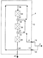
- fresh ammonia synthesis gas 2 is introduced into an ammonia reactor 4 being constructed according to a specific embodiment of the invention.
- the synthesis gas is introduced in two separate feed streams 6 and 10 through inlets 16 and 20 arranged in shell 12 of the reactor.
- Reactor 4 comprises within the shell a top catalyst bed 24, a second catalyst bed 26 and a bottom catalyst bed 28. Between beds 24 and 26 and between beds 26 and 28 heat exchangers 30 and 32 are arranged for cooling a partly converted process stream 37 leaving beds 24 and 26.
- Fresh synthesis gas is passed in process stream 36 to bed 24 and partly converted in bed 24.
- the partly converted synthesis gas is then passed in process stream 37 successively through beds 26 and 28.
- An ammonia rich product effluent 38 is withdrawn from the reactor through outlet 40.
- feed stream 6 is preheated by indirect heat exchange as described above.
- the preheated feedstream is then combined with fresh synthesis gas stream 10 to process stream 36 upstream top catalyst bed 24.
- the temperature of process stream 36 is adjusted by addition of the cold stream 10.
- reaction temperature in first and second catalyst bed 24 and 26, respectively is determined by the flow ratio between the inlet streams 6 and 10.
- the temperature of the fresh synthesis gas in stream 2 controls the temperature at inlet to bottom catalyst bed.
- a reactor as shown in Fig. 1 and explained in detail in the above description with a fixed size of pressure shell was operated at four different volume ratios between the first and second catalyst bed of the reactor.
- volume ratio of the first and second catalyst bed was between 0.5 and 3.0.
- a first experiment was conducted, whereby the inlet temperature to the second catalyst bed was adjusted to result in a maximum product yield.
- the inlet temperature into the second catalyst was varied between values above and below the optimum operation temperature and product yield determined for each volume ratio. The above conditions and results obtained thereby are summarised in the Table below.
- Bed2/Bed1 1539,3 1541,9 1544,4 1547,0 1544,3 1541,2 1538,0 0,50
- Bed1/Bed2 1543,4 1547,0 1550,6 1554,2 1550,6 1546,7 1542,7 0,80
- Bed2/Bed1 1543,4 1547,9 1552,6 1557,0 1552,7 1548,0 1543,4 1,00
- Bed2/Bed1 1538,4 1544,6 1550,9 1557,1 1551,4 1545,9 1541,2 1,50
- Bed2/Bed1 1524,0 1534,5 1543,9 1553,0 1547,4 1541,8 1533,6 2,00
- Bed2/Bed1 1498,6 1510,6 1522,7
- Bed2/Bed1 98,9 99,0 99,2 99,4 99,2 99,0 98,8 0,50
- Bed1/Bed2 99,1 99,4 99,6 99,8 99,6 99,3 99,1 0,80
- Bed2/Bed1 99,1 99,4 99,7 100,0 99,7 99,4 99,1 1,00
- Bed2/Bed1 98,8 99,2 99,6 100,0 99,6 99,3 99,0 1,50
- Bed2/Bed1 97,9 98,6 99,2 99,7 99,4 99,0 98,5 2,00
- Bed2/Bed1 96,2 97,0 97,8 98,5 98,0 97,4 96,9 3,00
Landscapes
- Chemical & Material Sciences (AREA)
- Organic Chemistry (AREA)
- Chemical Kinetics & Catalysis (AREA)
- Analytical Chemistry (AREA)
- Inorganic Chemistry (AREA)
- Devices And Processes Conducted In The Presence Of Fluids And Solid Particles (AREA)
- Organic Low-Molecular-Weight Compounds And Preparation Thereof (AREA)
- Physical Or Chemical Processes And Apparatus (AREA)
- Catalysts (AREA)
Abstract
Description
- The present invention relates to a process and reactor for the preparation of ammonia from a synthesis gas comprising nitrogen and hydrogen by passage of the synthesis gas through a number of catalyst beds with intermediate, indirect cooling of partially converted synthesis gas. In particular, the invention concerns an improved process of the above type and an ammonia reactor for use in the process, wherein the synthesis gas is reacted in contact with an iron based ammonia catalyst being arranged in a series of beds with a volume ratio between the first and second bed of nearly equity and with cooling of the partially converted synthesis gas by indirect heat exchange with a single stream of fresh synthesis gas.
- Industrial ammonia production from ammonia synthesis gas is most usually carried by contacting the gas with an iron catalyst being arranged in a number of adiabatically operated beds connected in series. Pressure, temperature and space velocity of the synthesis gas (defined as the volume of gas per hour at standard temperature and pressure passed over a unit volume of catalyst) control ammonia concentration in the product effluent gas. Owing a specific reaction kinetic and thermodynamic in the formation of ammonia from hydrogen and nitrogen in contact with an iron based ammonia catalyst, partial reacted synthesis gas must be cooled between each catalyst bed to obtain reasonable reaction yield. A further typical approach in the industry to raise ammonia yield is decreasing the space velocity as the gas passes through a series of catalyst beds by increasing catalyst volume in succeeding beds.
- Various types of ammonia converters are known in the art. Frequently employed reactor types are those having a number of catalyst beds with interbed heat exchangers for removing and controlling reaction heat between the beds.
- US Patent No. 4,181,701 discloses an ammonia reactor with a top and a bottom catalyst bed with a central heat exchanger mounted on one of the beds. A process stream of synthesis gas is obtained by combining inside the reactor separate feed streams:
a shell stream for cooling the reactor shell and cooling the product effluent, an exchange stream for cooling the central heat exchanger, and a by-pass stream for final adjustment of the temperature of the process stream. - Indirect cooling of partially converted ammonia synthesis gas in a reactor with more than two catalyst beds is, furthermore, known in the art and conventionally applied for in the industry.
- Thereby, the synthesis gas is indirectly cooled with fresh synthesis gas being passed in a number of separate streams to heat exchangers between the catalyst beds. The streams are introduced through separate pipe connections mounted on the reactor shell.
- The major drawback of the known ammonia preparation processes and reactors with intermediate cooling of partially converted synthesis gas in a number of interbed heat exchangers with separate gas streams is the need for numerous inlet means and complicated ducting in the ammonia reactor.
- An ammonia production process and reactor of the above type with simplified gas handling and ducting is mentioned in EP-A-873,972. By the process and reactor of this patent publication, a process stream is obtained by combining prior to introduction into a first catalyst bed, a first feed stream of synthesis gas having been preheated through indirect heat exchange during the intermediate cooling of the partially converted synthesis gas, a second feed stream of synthesis gas having been preheated by indirect heat exchange with the product effluent, and a third feed stream of synthesis gas for adjustment of temperature of the process stream. The first feed stream is passed successively through the interbed heat exchangers for cooling the partially converted synthesis gas.
- The above mentioned known ammonia reactors and processes are operated on conventional iron based catalysts with a main constituent of magnetite being reduced during operation to the catalytically active form of alpha-iron.
- Recently, ammonia catalysts with high activity composed of ruthenium on graphite support have been employed in a number of industrial ammonia reactors. The main advantage of ruthenium ammonia catalysts is a higher volumetric activity and less catalyst volume required for product yields comparable to those obtained by use of the conventional iron catalyst. In EP-A-931,586 an ammonia reactor is disclosed with a top and central catalyst bed being loaded with conventional iron ammonia catalyst and a bottom catalyst with less volume than the top and central bed being loaded with ruthenium-on-carbon catalyst. A process stream of ammonia synthesis gas is in the above indirectly cooled reactor obtained by combining three separate inlet streams upstream the top catalyst bed.
- Though the high activity ruthenium based ammonia catalysts allow reduction of catalyst volume, the main disadvantage of ruthenium based catalysts is less mechanical stability and considerably higher costs, which are not sufficient to compensate for the reduced catalyst volume necessary in the application of these catalysts.
- It has now been found that gas handling and ducting in multibed ammonia processes and reactors with indirect cooling of the process gas and being operated on conventionally iron ammonia catalysts are still improved at comparative ammonia product yield, when reducing the number of separate synthesis gas inlet streams in the formation a process gas steam and through adjustment of process gas space velocity in the different catalyst beds.
- Pursuant to the above finding, this invention is a process for the preparation of ammonia at elevated pressure and temperature in an ammonia reactor comprising passing a process stream of ammonia synthesis gas successively through at least three catalyst beds and reacting the synthesis gas in the beds;
intermediately cooling of partially reacted synthesis gas leaving the catalyst beds by heat exchange in heat exchangers arranged between each catalyst bed and withdrawing a product effluent being rich in ammonia, wherein the process stream is obtained by combining prior to introduction into a first catalyst bed, a first feed stream of synthesis gas having been preheated through indirect heat exchange during the intermediate cooling of the partially converted synthesis gas and a second feed stream of synthesis gas for adjustment of temperature of the process stream, the first feed stream is passed successively through the interbed heat exchangers for cooling the partially converted synthesis gas and wherein space velocity of the process gas in the second catalyst bed is between 0.65 and 2.00 times of the space velocity in the first catalyst bed. - Furthermore, the invention provides an ammonia reactor for use in the above process with simplified inlet and piping means for distribution of fresh synthesis gas serving as cooling medium in indirect heat exchange with partially reacted synthesis gas between each catalyst bed.
- Thus, an ammonia reactor according to the invention, comprises within a cylindrical pressure shell at least a top, a second and a bottom catalyst bed vertically arranged around a common axis and connected in series;
intermediate heat exchanging means arranged between each catalyst bed for intermediate cooling of a partially converted ammonia synthesis gas from the catalyst beds by indirect heat exchange with a first feed stream of fresh ammonia synthesis gas;
inlet means for introducing the first feed stream and inlet means for introducing a second feed stream into the reactor;
means for passing the first and the second feed stream to the top catalyst bed; and
means for combining the feed streams to a process stream prior to introduction of the process stream into the top catalyst bed, wherein the means for passing the first feed stream consists of a passageway for connecting in series the intermediate heat exchangers and for passing the first stream from the inlet means consecutively through the intermediate heat exchanging means to the means for combining the feed streams and wherein volume ratio between the second catalyst bed and the top catalyst bed is between 0.5 and 1.5. - The invention will be explained in more detail in the following description by reference to the drawings, in which the sole Figure shows in pure schematic form a sectional view of an ammonia reactor according to a specific embodiment of the invention.
- When operating the invention, fresh ammonia synthesis gas 2 is introduced into an ammonia reactor 4 being constructed according to a specific embodiment of the invention. The synthesis gas is introduced in two
separate feed streams inlets shell 12 of the reactor. Reactor 4 comprises within the shell atop catalyst bed 24, asecond catalyst bed 26 and abottom catalyst bed 28. Betweenbeds beds heat exchangers process stream 37 leavingbeds process stream 36 tobed 24 and partly converted inbed 24. The partly converted synthesis gas is then passed inprocess stream 37 successively throughbeds rich product effluent 38 is withdrawn from the reactor throughoutlet 40. - As mentioned hereinbefore, the reaction between hydrogen and nitrogen proceeds exothermically in the catalyst beds and the temperature of the process stream rises. Because of thermodynamically reasons the temperature of
process stream 37 has to be lowered, prior to being introduced intobeds heat exchangers feed stream 6, being passed in series throughheat exchangers - By passage through the heat
exchangers feed stream 6 is preheated by indirect heat exchange as described above. The preheated feedstream is then combined with freshsynthesis gas stream 10 to processstream 36 upstreamtop catalyst bed 24. The temperature ofprocess stream 36 is adjusted by addition of thecold stream 10. - In the above reactor, the reaction temperature in first and
second catalyst bed inlet streams - It is not possible in an ammonia reactor with more than two catalyst beds to control the inlet temperature in the second catalyst bed with the above two streams within an optimum temperature.
- In the process and reactor according to the invention deviation from optimum temperature in the second catalyst beds, however, will only have a minor impact on ammonia product yield with a volume ratio or space velocity between the first and second catalyst bed as specified hereinbefore and further shown in the following Example.
- A reactor as shown in Fig. 1 and explained in detail in the above description with a fixed size of pressure shell was operated at four different volume ratios between the first and second catalyst bed of the reactor. In the experiments volume ratio of the first and second catalyst bed was between 0.5 and 3.0. For each volume ratio, a first experiment was conducted, whereby the inlet temperature to the second catalyst bed was adjusted to result in a maximum product yield. In the following experiments the inlet temperature into the second catalyst was varied between values above and below the optimum operation temperature and product yield determined for each volume ratio. The above conditions and results obtained thereby are summarised in the Table below.
- To compare impact of temperature deviation on product yield at each volume ratio with product yield at the optimum temperature the yield at the optimum temperature is 100%.
Dev from optimium inlet temp. -20 -16 -11 0 11 16 20 Prod rate, MTPD Bed2/Bed1 = 1539,3 1541,9 1544,4 1547,0 1544,3 1541,2 1538,0 0,50 Bed1/Bed2 = 1543,4 1547,0 1550,6 1554,2 1550,6 1546,7 1542,7 0,80 Bed2/Bed1 = 1543,4 1547,9 1552,6 1557,0 1552,7 1548,0 1543,4 1,00 Bed2/Bed1 = 1538,4 1544,6 1550,9 1557,1 1551,4 1545,9 1541,2 1,50 Bed2/Bed1 = 1524,0 1534,5 1543,9 1553,0 1547,4 1541,8 1533,6 2,00 Bed2/Bed1 = 1498,6 1510,6 1522,7 1534,0 1525,2 1517,0 1509,4 3,00 Prod. rate, % Bed2/Bed1 = 98,9 99,0 99,2 99,4 99,2 99,0 98,8 0,50 Bed1/Bed2 = 99,1 99,4 99,6 99,8 99,6 99,3 99,1 0,80 Bed2/Bed1 = 99,1 99,4 99,7 100,0 99,7 99,4 99,1 1,00 Bed2/Bed1 = 98,8 99,2 99,6 100,0 99,6 99,3 99,0 1,50 Bed2/Bed1 = 97,9 98,6 99,2 99,7 99,4 99,0 98,5 2,00 Bed2/Bed1 = 96,2 97,0 97,8 98,5 98,0 97,4 96,9 3,00 - As apparent from the above results, decrease of product yield at deviation from the optimum operation temperature in the second catalyst bed is less severe in a reactor or process having a distribution of catalyst volume in the second and first bed between 0.5 and 1.5 according to the invention compared to the results obtained with a reactor and process operating with a corresponding catalyst volume ratio of between 2.0 and 3.0 as known in the art and generally employed in ammonia industry. As a further advantage, product yield is increased when sizing the first and second catalyst according to the invention with the above volume ratio of between 0.5 and 1.5. At a volume ratio of between 1.0 and 1.5, the product yield in tons per day at optimum temperature conditions is about 2% higher compared to the optimum yield obtained at a typical employed catalyst volume ratio of 3.0.
Claims (3)
- Process for the preparation of ammonia at elevated pressure and temperature in an ammonia reactor, comprising passing a process stream of ammonia synthesis gas successively through at least three beds with an iron based ammonia formation catalyst and reacting the synthesis gas in the beds;
intermediately cooling of partially reacted synthesis gas leaving the catalyst beds by heat exchange in heat exchangers arranged between each catalyst bed and withdrawing a product effluent being rich in ammonia, wherein the process stream is obtained by combining prior to introduction into a first catalyst bed, a first feed stream of synthesis gas having been preheated through indirect heat exchange during the intermediate cooling of the partially converted synthesis gas and a second feed stream of synthesis gas for adjustment of temperature of the process stream, the first feed stream is passed successively through the interbed heat exchangers for cooling the partially converted synthesis gas and wherein space velocity of the process gas in a second catalyst bed is between 0.65 and 2.00 times of the space velocity in the first catalyst bed. - Ammonia reactor comprising within a cylindrical pressure shell at least a top, a second and a bottom catalyst bed loaded with an iron based ammonia formation catalyst and vertically arranged around a common axis and connected in series;
intermediate heat exchanging means arranged between each catalyst bed for intermediate cooling of a partially converted ammonia synthesis gas from the catalyst beds by indirect heat exchange with a first feed stream of fresh ammonia synthesis gas;
inlet means for introducing the first feed stream and inlet means for introducing a second feed stream into the reactor;
means for passing the first and the second feed stream to the top catalyst bed; and
means for combining the feed streams to a process stream prior to introduction of the process stream into the top catalyst bed, wherein the means for passing the first feed stream consists of a passage-way for connecting in series the intermediate heat exchangers and for passing the first stream from the inlet means consecutively through the intermediate heat exchanging means to the means for combining the feed streams and wherein volume ratio between the second catalyst bed and the top catalyst bed is between 0.5 and 1.5. - Ammonia reactor of claim 2, wherein the pressure shell is a shell of an existing ammonia reactor.
Applications Claiming Priority (4)
| Application Number | Priority Date | Filing Date | Title |
|---|---|---|---|
| DKPA200000207 | 2000-02-10 | ||
| DK200000207 | 2000-02-10 | ||
| DKPA200000248 | 2000-02-17 | ||
| DK200000248 | 2000-02-17 |
Publications (2)
| Publication Number | Publication Date |
|---|---|
| EP1123899A1 true EP1123899A1 (en) | 2001-08-16 |
| EP1123899B1 EP1123899B1 (en) | 2004-10-13 |
Family
ID=26068762
Family Applications (1)
| Application Number | Title | Priority Date | Filing Date |
|---|---|---|---|
| EP01101508A Expired - Lifetime EP1123899B1 (en) | 2000-02-10 | 2001-01-24 | Process and reactor for the preparation of ammonia |
Country Status (11)
| Country | Link |
|---|---|
| US (1) | US6540971B2 (en) |
| EP (1) | EP1123899B1 (en) |
| JP (1) | JP5046437B2 (en) |
| KR (1) | KR100445253B1 (en) |
| CN (1) | CN1205123C (en) |
| AT (1) | ATE279374T1 (en) |
| CA (1) | CA2335384C (en) |
| DE (1) | DE60106306T2 (en) |
| NO (1) | NO331614B1 (en) |
| RU (1) | RU2262482C2 (en) |
| TW (1) | TWI281458B (en) |
Cited By (1)
| Publication number | Priority date | Publication date | Assignee | Title |
|---|---|---|---|---|
| EP4691987A1 (en) * | 2024-08-08 | 2026-02-11 | Linde GmbH | Method and installation for producing a process product |
Families Citing this family (16)
| Publication number | Priority date | Publication date | Assignee | Title |
|---|---|---|---|---|
| JP5373410B2 (en) | 2009-01-09 | 2013-12-18 | トヨタ自動車株式会社 | Ammonia synthesis method |
| RU2012131425A (en) | 2009-12-23 | 2014-01-27 | Колгейт-Палмолив Компани | ORGANIC CARE COMPOSITIONS |
| US9174070B2 (en) | 2010-12-22 | 2015-11-03 | Colgate-Palmolive Company | Oral care compositions |
| CN102502700B (en) * | 2011-10-21 | 2014-12-24 | 山西省霍州市化学工业有限责任公司 | Method for replacing catalyst of synthesis system |
| CN102500427A (en) * | 2011-10-21 | 2012-06-20 | 山西省霍州市化学工业有限责任公司 | Curing method of novel catalyst |
| JP5821777B2 (en) * | 2012-05-21 | 2015-11-24 | トヨタ自動車株式会社 | Ammonia synthesis method |
| EP3115338A1 (en) * | 2015-07-07 | 2017-01-11 | Casale SA | A method for revamping an ammonia converter |
| WO2017151769A1 (en) | 2016-03-01 | 2017-09-08 | Beach Joseph | Electrically enhanced haber-bosch (eehb) anhydrous ammonia synthesis |
| CN116637616A (en) | 2017-05-15 | 2023-08-25 | 星火能源 | A kind of method for preparing catalyst carrier material |
| US10787367B2 (en) * | 2017-05-26 | 2020-09-29 | Starfire Energy | Removal of gaseous NH3 from an NH3 reactor product stream |
| EP3713662A4 (en) | 2017-11-25 | 2021-09-22 | Starfire Energy | CHEMICAL REACTOR WITH INTEGRATED HEAT EXCHANGER |
| US11772979B2 (en) | 2019-01-31 | 2023-10-03 | Starfire Energy | Metal-decorated barium calcium aluminum oxide catalyst for NH3 synthesis and cracking and methods of forming the same |
| CN113474282B (en) | 2019-02-28 | 2025-03-11 | 托普索公司 | Production of synthesis gas by steam methane reforming |
| WO2022216666A1 (en) | 2021-04-08 | 2022-10-13 | Colgate-Palmolive Company | Oral care compositions |
| CN114307869A (en) * | 2021-12-17 | 2022-04-12 | 南京敦先化工科技有限公司 | Ammonia synthesis reactor |
| EP4434615A1 (en) * | 2023-03-24 | 2024-09-25 | L'air Liquide, Societe Anonyme Pour L'etude Et L'exploitation Des Procedes Georges Claude | Process for producing synthesis gas product comprising hydrogen |
Citations (5)
| Publication number | Priority date | Publication date | Assignee | Title |
|---|---|---|---|---|
| EP0007743A1 (en) * | 1978-07-17 | 1980-02-06 | The M. W. Kellogg Company | Synthesis of ammonia and converter system therefor |
| EP0026057A1 (en) * | 1979-09-14 | 1981-04-01 | Imperial Chemical Industries Plc | Synthesis reactor and processes |
| EP0121355A2 (en) * | 1983-03-07 | 1984-10-10 | Exxon Research And Engineering Company | Improved catalytic gas synthesis process and apparatus |
| EP0222069A2 (en) * | 1985-09-13 | 1987-05-20 | Ammonia Casale S.A. | Converter for heterogeneous synthesis more particularly for ammonia, methanol and higher alcohols |
| EP0873972A2 (en) * | 1997-04-21 | 1998-10-28 | Haldor Topsoe A/S | Process and reactor for the preparation of ammonia |
Family Cites Families (11)
| Publication number | Priority date | Publication date | Assignee | Title |
|---|---|---|---|---|
| US3721532A (en) * | 1971-02-08 | 1973-03-20 | Braun Co C | Ammonia synthesis system |
| GB1574723A (en) | 1976-03-10 | 1980-09-10 | Haldor Topsoe As | Apparatus for the synthesis of ammonia |
| US4230669A (en) * | 1978-07-17 | 1980-10-28 | Pullman Incorporated | Radial ammonia converter |
| FR2473032A1 (en) * | 1980-01-07 | 1981-07-10 | Banquy David | PROCESS FOR THE PRODUCTION OF AMMONIA AND THE SYNTHESIS GAS CORRESPONDING |
| DE3363367D1 (en) * | 1982-04-14 | 1986-06-12 | Ici Plc | Ammonia production process |
| US4867959A (en) * | 1986-11-20 | 1989-09-19 | Santa Fe Braun, Inc. | Process for synthesizing ammonia |
| DE3725564A1 (en) * | 1987-08-01 | 1989-02-09 | Uhde Gmbh | METHOD AND SYSTEM FOR CARRYING OUT A SYNTHESIS, IN PARTICULAR FOR THE SYNTHESIS OF AMMONIA |
| DE68906006T2 (en) * | 1988-12-21 | 1993-08-12 | Ammonia Casale Sa | REACTORS FOR HETEROGENEOUS SYNTHESIS. |
| KR940008073Y1 (en) * | 1990-08-31 | 1994-11-21 | 삼성항공산업 주식회사 | Driving device of horizontal jointed robot tool |
| EP0550525B1 (en) * | 1990-09-24 | 1995-08-02 | C F Braun Inc. | High conversion ammonia synthesis |
| EP0931586B1 (en) | 1997-11-28 | 2005-03-16 | Ammonia Casale S.A. | Method for in-situ modernization of a heterogeneous exothermic synthesis reactor |
-
2001
- 2001-01-24 EP EP01101508A patent/EP1123899B1/en not_active Expired - Lifetime
- 2001-01-24 DE DE60106306T patent/DE60106306T2/en not_active Expired - Lifetime
- 2001-01-24 AT AT01101508T patent/ATE279374T1/en not_active IP Right Cessation
- 2001-01-30 TW TW090101774A patent/TWI281458B/en not_active IP Right Cessation
- 2001-02-05 US US09/777,097 patent/US6540971B2/en not_active Expired - Lifetime
- 2001-02-07 JP JP2001031385A patent/JP5046437B2/en not_active Expired - Lifetime
- 2001-02-09 CA CA002335384A patent/CA2335384C/en not_active Expired - Lifetime
- 2001-02-09 CN CNB011116706A patent/CN1205123C/en not_active Expired - Lifetime
- 2001-02-09 NO NO20010690A patent/NO331614B1/en not_active IP Right Cessation
- 2001-02-09 RU RU2001103540/15A patent/RU2262482C2/en active
- 2001-02-10 KR KR10-2001-0006579A patent/KR100445253B1/en not_active Expired - Lifetime
Patent Citations (5)
| Publication number | Priority date | Publication date | Assignee | Title |
|---|---|---|---|---|
| EP0007743A1 (en) * | 1978-07-17 | 1980-02-06 | The M. W. Kellogg Company | Synthesis of ammonia and converter system therefor |
| EP0026057A1 (en) * | 1979-09-14 | 1981-04-01 | Imperial Chemical Industries Plc | Synthesis reactor and processes |
| EP0121355A2 (en) * | 1983-03-07 | 1984-10-10 | Exxon Research And Engineering Company | Improved catalytic gas synthesis process and apparatus |
| EP0222069A2 (en) * | 1985-09-13 | 1987-05-20 | Ammonia Casale S.A. | Converter for heterogeneous synthesis more particularly for ammonia, methanol and higher alcohols |
| EP0873972A2 (en) * | 1997-04-21 | 1998-10-28 | Haldor Topsoe A/S | Process and reactor for the preparation of ammonia |
Cited By (1)
| Publication number | Priority date | Publication date | Assignee | Title |
|---|---|---|---|---|
| EP4691987A1 (en) * | 2024-08-08 | 2026-02-11 | Linde GmbH | Method and installation for producing a process product |
Also Published As
| Publication number | Publication date |
|---|---|
| DE60106306T2 (en) | 2006-02-23 |
| KR20010082120A (en) | 2001-08-29 |
| CN1205123C (en) | 2005-06-08 |
| CN1309083A (en) | 2001-08-22 |
| JP2001240412A (en) | 2001-09-04 |
| NO20010690L (en) | 2001-08-13 |
| TWI281458B (en) | 2007-05-21 |
| EP1123899B1 (en) | 2004-10-13 |
| NO20010690D0 (en) | 2001-02-09 |
| NO331614B1 (en) | 2012-02-06 |
| DE60106306D1 (en) | 2004-11-18 |
| US20010018039A1 (en) | 2001-08-30 |
| CA2335384C (en) | 2008-12-30 |
| ATE279374T1 (en) | 2004-10-15 |
| CA2335384A1 (en) | 2001-08-10 |
| RU2262482C2 (en) | 2005-10-20 |
| KR100445253B1 (en) | 2004-08-21 |
| US6540971B2 (en) | 2003-04-01 |
| JP5046437B2 (en) | 2012-10-10 |
Similar Documents
| Publication | Publication Date | Title |
|---|---|---|
| EP1123899B1 (en) | Process and reactor for the preparation of ammonia | |
| US4411877A (en) | Synthesis processes | |
| US5631302A (en) | Process of producing methanol | |
| AU627281B2 (en) | Exothermic reactions | |
| CN1989092B (en) | Process for gas phase reactions | |
| EP0080270B1 (en) | Synthesis process and reactor | |
| AU2004205368B2 (en) | Methanol synthesis | |
| JPH0449147Y2 (en) | ||
| US4452760A (en) | Horizontal ammonia converter | |
| US6015537A (en) | Process and reactor for the preparation of ammonia | |
| EP0550525B1 (en) | High conversion ammonia synthesis | |
| EP0121355B1 (en) | Improved catalytic gas synthesis process and apparatus | |
| US4938930A (en) | Reaction vessel | |
| EP1707259B1 (en) | Process for the heterogeneous synthesis of chemical compounds | |
| US3998932A (en) | Process for the catalytic synthesis of ammonia | |
| US4789527A (en) | Catalytic gas synthesis apparatus | |
| US4637918A (en) | Catalytic gas synthesis apparatus | |
| MXPA01001514A (en) | Process and reactor for the preparation of ammonia | |
| MXPA98002989A (en) | Process and reactor for ammoni preparation |
Legal Events
| Date | Code | Title | Description |
|---|---|---|---|
| PUAI | Public reference made under article 153(3) epc to a published international application that has entered the european phase |
Free format text: ORIGINAL CODE: 0009012 |
|
| AK | Designated contracting states |
Kind code of ref document: A1 Designated state(s): AT BE CH CY DE DK ES FI FR GB GR IE IT LI LU MC NL PT SE TR |
|
| AX | Request for extension of the european patent |
Free format text: AL;LT;LV;MK;RO;SI |
|
| 17P | Request for examination filed |
Effective date: 20020218 |
|
| AKX | Designation fees paid |
Free format text: AT BE CH CY DE DK ES FI FR GB GR IE IT LI LU MC NL PT SE TR |
|
| R17P | Request for examination filed (corrected) |
Effective date: 20020218 |
|
| 17Q | First examination report despatched |
Effective date: 20021218 |
|
| GRAP | Despatch of communication of intention to grant a patent |
Free format text: ORIGINAL CODE: EPIDOSNIGR1 |
|
| GRAS | Grant fee paid |
Free format text: ORIGINAL CODE: EPIDOSNIGR3 |
|
| GRAA | (expected) grant |
Free format text: ORIGINAL CODE: 0009210 |
|
| AK | Designated contracting states |
Kind code of ref document: B1 Designated state(s): AT BE CH CY DE DK ES FI FR GB GR IE IT LI LU MC NL PT SE TR |
|
| PG25 | Lapsed in a contracting state [announced via postgrant information from national office to epo] |
Ref country code: FI Free format text: LAPSE BECAUSE OF FAILURE TO SUBMIT A TRANSLATION OF THE DESCRIPTION OR TO PAY THE FEE WITHIN THE PRESCRIBED TIME-LIMIT Effective date: 20041013 Ref country code: NL Free format text: LAPSE BECAUSE OF FAILURE TO SUBMIT A TRANSLATION OF THE DESCRIPTION OR TO PAY THE FEE WITHIN THE PRESCRIBED TIME-LIMIT Effective date: 20041013 Ref country code: TR Free format text: LAPSE BECAUSE OF FAILURE TO SUBMIT A TRANSLATION OF THE DESCRIPTION OR TO PAY THE FEE WITHIN THE PRESCRIBED TIME-LIMIT Effective date: 20041013 Ref country code: AT Free format text: LAPSE BECAUSE OF FAILURE TO SUBMIT A TRANSLATION OF THE DESCRIPTION OR TO PAY THE FEE WITHIN THE PRESCRIBED TIME-LIMIT Effective date: 20041013 Ref country code: BE Free format text: LAPSE BECAUSE OF FAILURE TO SUBMIT A TRANSLATION OF THE DESCRIPTION OR TO PAY THE FEE WITHIN THE PRESCRIBED TIME-LIMIT Effective date: 20041013 |
|
| REG | Reference to a national code |
Ref country code: GB Ref legal event code: FG4D |
|
| REG | Reference to a national code |
Ref country code: CH Ref legal event code: EP |
|
| REG | Reference to a national code |
Ref country code: IE Ref legal event code: FG4D |
|
| REF | Corresponds to: |
Ref document number: 60106306 Country of ref document: DE Date of ref document: 20041118 Kind code of ref document: P |
|
| REG | Reference to a national code |
Ref country code: CH Ref legal event code: NV Representative=s name: PATENTANWAELTE FELDMANN & PARTNER AG |
|
| PGFP | Annual fee paid to national office [announced via postgrant information from national office to epo] |
Ref country code: NL Payment date: 20041229 Year of fee payment: 5 |
|
| PG25 | Lapsed in a contracting state [announced via postgrant information from national office to epo] |
Ref country code: DK Free format text: LAPSE BECAUSE OF FAILURE TO SUBMIT A TRANSLATION OF THE DESCRIPTION OR TO PAY THE FEE WITHIN THE PRESCRIBED TIME-LIMIT Effective date: 20050113 Ref country code: GR Free format text: LAPSE BECAUSE OF FAILURE TO SUBMIT A TRANSLATION OF THE DESCRIPTION OR TO PAY THE FEE WITHIN THE PRESCRIBED TIME-LIMIT Effective date: 20050113 Ref country code: SE Free format text: LAPSE BECAUSE OF FAILURE TO SUBMIT A TRANSLATION OF THE DESCRIPTION OR TO PAY THE FEE WITHIN THE PRESCRIBED TIME-LIMIT Effective date: 20050113 |
|
| PG25 | Lapsed in a contracting state [announced via postgrant information from national office to epo] |
Ref country code: IE Free format text: LAPSE BECAUSE OF NON-PAYMENT OF DUE FEES Effective date: 20050124 Ref country code: LU Free format text: LAPSE BECAUSE OF NON-PAYMENT OF DUE FEES Effective date: 20050124 Ref country code: CY Free format text: LAPSE BECAUSE OF FAILURE TO SUBMIT A TRANSLATION OF THE DESCRIPTION OR TO PAY THE FEE WITHIN THE PRESCRIBED TIME-LIMIT Effective date: 20050124 Ref country code: ES Free format text: LAPSE BECAUSE OF FAILURE TO SUBMIT A TRANSLATION OF THE DESCRIPTION OR TO PAY THE FEE WITHIN THE PRESCRIBED TIME-LIMIT Effective date: 20050124 |
|
| PG25 | Lapsed in a contracting state [announced via postgrant information from national office to epo] |
Ref country code: MC Free format text: LAPSE BECAUSE OF NON-PAYMENT OF DUE FEES Effective date: 20050131 |
|
| NLV1 | Nl: lapsed or annulled due to failure to fulfill the requirements of art. 29p and 29m of the patents act | ||
| ET | Fr: translation filed | ||
| PLBE | No opposition filed within time limit |
Free format text: ORIGINAL CODE: 0009261 |
|
| STAA | Information on the status of an ep patent application or granted ep patent |
Free format text: STATUS: NO OPPOSITION FILED WITHIN TIME LIMIT |
|
| 26N | No opposition filed |
Effective date: 20050714 |
|
| REG | Reference to a national code |
Ref country code: IE Ref legal event code: MM4A |
|
| REG | Reference to a national code |
Ref country code: CH Ref legal event code: PFA Owner name: HALDOR TOPSOE A/S Free format text: HALDOR TOPSOE A/S#NYMOLLEVEJ 55#2800 KGS. LYNGBY (DK) -TRANSFER TO- HALDOR TOPSOE A/S#NYMOLLEVEJ 55#2800 KGS. LYNGBY (DK) |
|
| PG25 | Lapsed in a contracting state [announced via postgrant information from national office to epo] |
Ref country code: PT Free format text: LAPSE BECAUSE OF NON-PAYMENT OF DUE FEES Effective date: 20050313 |
|
| REG | Reference to a national code |
Ref country code: FR Ref legal event code: PLFP Year of fee payment: 16 |
|
| REG | Reference to a national code |
Ref country code: FR Ref legal event code: PLFP Year of fee payment: 17 |
|
| REG | Reference to a national code |
Ref country code: FR Ref legal event code: PLFP Year of fee payment: 18 |
|
| PGFP | Annual fee paid to national office [announced via postgrant information from national office to epo] |
Ref country code: IT Payment date: 20200123 Year of fee payment: 20 Ref country code: GB Payment date: 20200129 Year of fee payment: 20 |
|
| PGFP | Annual fee paid to national office [announced via postgrant information from national office to epo] |
Ref country code: CH Payment date: 20200127 Year of fee payment: 20 |
|
| PGFP | Annual fee paid to national office [announced via postgrant information from national office to epo] |
Ref country code: FR Payment date: 20200128 Year of fee payment: 20 |
|
| PGFP | Annual fee paid to national office [announced via postgrant information from national office to epo] |
Ref country code: DE Payment date: 20200327 Year of fee payment: 20 |
|
| REG | Reference to a national code |
Ref country code: CH Ref legal event code: PFA Owner name: HALDOR TOPSOE A/S, DK Free format text: FORMER OWNER: HALDOR TOPSOE A/S, DK |
|
| REG | Reference to a national code |
Ref country code: DE Ref legal event code: R071 Ref document number: 60106306 Country of ref document: DE |
|
| REG | Reference to a national code |
Ref country code: CH Ref legal event code: PL |
|
| REG | Reference to a national code |
Ref country code: GB Ref legal event code: PE20 Expiry date: 20210123 |
|
| PG25 | Lapsed in a contracting state [announced via postgrant information from national office to epo] |
Ref country code: GB Free format text: LAPSE BECAUSE OF EXPIRATION OF PROTECTION Effective date: 20210123 |