EP1123866A2 - A unit for feeding and applying seals to security cassettes for banknotes - Google Patents
A unit for feeding and applying seals to security cassettes for banknotes Download PDFInfo
- Publication number
- EP1123866A2 EP1123866A2 EP01830073A EP01830073A EP1123866A2 EP 1123866 A2 EP1123866 A2 EP 1123866A2 EP 01830073 A EP01830073 A EP 01830073A EP 01830073 A EP01830073 A EP 01830073A EP 1123866 A2 EP1123866 A2 EP 1123866A2
- Authority
- EP
- European Patent Office
- Prior art keywords
- seal
- seals
- parts
- unit
- gripping
- Prior art date
- Legal status (The legal status is an assumption and is not a legal conclusion. Google has not performed a legal analysis and makes no representation as to the accuracy of the status listed.)
- Withdrawn
Links
- NJPPVKZQTLUDBO-UHFFFAOYSA-N novaluron Chemical compound C1=C(Cl)C(OC(F)(F)C(OC(F)(F)F)F)=CC=C1NC(=O)NC(=O)C1=C(F)C=CC=C1F NJPPVKZQTLUDBO-UHFFFAOYSA-N 0.000 description 2
- 238000010586 diagram Methods 0.000 description 1
- 230000000717 retained effect Effects 0.000 description 1
- 239000011435 rock Substances 0.000 description 1
- 238000007789 sealing Methods 0.000 description 1
Images


Classifications
-
- B—PERFORMING OPERATIONS; TRANSPORTING
- B65—CONVEYING; PACKING; STORING; HANDLING THIN OR FILAMENTARY MATERIAL
- B65B—MACHINES, APPARATUS OR DEVICES FOR, OR METHODS OF, PACKAGING ARTICLES OR MATERIALS; UNPACKING
- B65B7/00—Closing containers or receptacles after filling
- B65B7/16—Closing semi-rigid or rigid containers or receptacles not deformed by, or not taking-up shape of, contents, e.g. boxes or cartons
- B65B7/26—Closing semi-rigid or rigid containers or receptacles not deformed by, or not taking-up shape of, contents, e.g. boxes or cartons by closing hinged lids
-
- Y—GENERAL TAGGING OF NEW TECHNOLOGICAL DEVELOPMENTS; GENERAL TAGGING OF CROSS-SECTIONAL TECHNOLOGIES SPANNING OVER SEVERAL SECTIONS OF THE IPC; TECHNICAL SUBJECTS COVERED BY FORMER USPC CROSS-REFERENCE ART COLLECTIONS [XRACs] AND DIGESTS
- Y10—TECHNICAL SUBJECTS COVERED BY FORMER USPC
- Y10T—TECHNICAL SUBJECTS COVERED BY FORMER US CLASSIFICATION
- Y10T156/00—Adhesive bonding and miscellaneous chemical manufacture
- Y10T156/17—Surface bonding means and/or assemblymeans with work feeding or handling means
- Y10T156/1702—For plural parts or plural areas of single part
- Y10T156/1744—Means bringing discrete articles into assembled relationship
-
- Y—GENERAL TAGGING OF NEW TECHNOLOGICAL DEVELOPMENTS; GENERAL TAGGING OF CROSS-SECTIONAL TECHNOLOGIES SPANNING OVER SEVERAL SECTIONS OF THE IPC; TECHNICAL SUBJECTS COVERED BY FORMER USPC CROSS-REFERENCE ART COLLECTIONS [XRACs] AND DIGESTS
- Y10—TECHNICAL SUBJECTS COVERED BY FORMER USPC
- Y10T—TECHNICAL SUBJECTS COVERED BY FORMER US CLASSIFICATION
- Y10T156/00—Adhesive bonding and miscellaneous chemical manufacture
- Y10T156/17—Surface bonding means and/or assemblymeans with work feeding or handling means
- Y10T156/1702—For plural parts or plural areas of single part
- Y10T156/1744—Means bringing discrete articles into assembled relationship
- Y10T156/1751—At least three articles
- Y10T156/1761—Stacked serially
Definitions
- the present invention relates to a unit for feeding and applying seals to security cassettes for banknotes.
- the invention finds application to advantage in machines by which banknotes are put into relative security cassettes, the art field to which explicit reference is made in the following specification albeit implying no limitation in general scope.
- banknotes are first sorted into groups and then put into bags or into security cassettes, as mentioned above, for the purposes of handling and transport.
- the cassettes are conventional in embodiment, consisting in a container and a lid hinged to the container, of which the lid can be secured in the closed position by a removable fastening mechanism that comprises a catch element associated with a portion of the lid, and a latch and clamp element operating in conjunction with a portion of the container.
- the fastening mechanism incorporates two slots, which, when the mechanism is placed in the operating condition to close the cassette, will accommodate two lugs projecting respectively from the lid and from the container, affording respective through holes positioned to receive the teeth of a seal.
- the seal comprises two parts designed to couple together non-releasably, hinged one to another and manoeuvrable thus from a condition in which the seal is open to a closed condition in which the teeth are inserted into the through holes of the lugs, integral respectively with the lid and with the container, thereby securing the cassette.
- the object of the present invention is to provide a unit for feeding and applying seals to security cassettes containing banknotes such as will render the operation of sealing the cassettes completely automatic.
- the stated object is realized in a unit according to the present invention for feeding and applying seals to security cassettes for banknotes, wherein the cassette comprises a container and a lid, the seal is composed of at least two parts affording respective latch means designed to engage relative receiving means afforded both by the container and by the lid, and the parts of the seal are designed to couple together non-releasably and manoeuvrable from an open condition to a closed condition in which the cassette is secured through the agency of the latch means, characterized in that it comprises feed means by which the seals are handled in the open condition, means by which the selfsame seals are gripped and positioned alongside the receiving means in an operating position, and means by which the two parts of the seal are coupled together in such a way as to bring about the closed condition.
- 1 denotes a unit, in its entirety, for feeding and applying seals 2 to security cassettes 3 containing banknotes.
- the single cassette 3 is substantially parallelepiped in appearance, with a predominating longitudinal axis A, and comprises a container 4, also a lid 5 associated pivotably with the container 4 by way of a hinge 6 disposed transversely to the axis A and coinciding with a rear face 7 of the cassette 3.
- the lid 5 can be locked in the position which closes the container 4 through the agency of a removable fastening mechanism 8 associated with a front face 9 of the cassette 3 opposite to the rear face 7.
- the fastening mechanism 8 which is of familiar embodiment and illustrated in figures 3, 6, 8, 9 and 12, consists essentially in a plate 10 by which the lid 5 is retained in its closed position on the container 4, affording two slots 11 arranged in such a way that when the cassette 3 is closed and the plate 10 in the retaining position, they will accommodate two lugs 12 integral respectively with the lid 5 and with the container 4.
- the portions of the lugs 12 that project from the plate 10 afford respective through holes 13 with axes 13a disposed transversely to the longitudinal axis A of the cassette.
- the single seal 2 comprises two parts 14 and 15 consisting in respective flat box elements 16 and 17 connected one to another by way of a hinge 18.
- Each box element 16 and 17 is compassed by a pair of larger side walls extending transversely to the hinge 18, denoted 19 and 19a in the case of the one part 14 and denoted 20 and 20a in the case of the other part 15.
- the walls denoted 19 and 20 lie substantially within one common plane, and the walls denoted 19a and 20a lie substantially within another common plane.
- one box element 16 presents a first pair of smaller side walls disposed parallel to the hinge 18, constituting the internal flank face 21 and the external flank face 22 of the respective part 14, whilst the other box element 17 presents a second pair of smaller side walls disposed parallel to the hinge 18, likewise constituting the internal flank face 23 and the external flank face 24 of the respective part 15, the internal flank faces 21 and 23 being the two faces that are drawn together when the seal 2 is closed.
- flank face 23 presents a hook 25 positioned to snap non-releasably into a socket 26 afforded by the other flank face 21 and thus render the seal 2 unopenable, that is to say, the seal can be opened only by being broken.
- the external flank faces 22 and 24 present respective curved teeth 27 positioned near the hinge 18, shown to advantage in the perspective view of figure 11, constituting latch means 28 which at the moment of closing the seal 2 are inserted into the respective through holes 13 of the two lugs 12, these in turn constituting receiving means for the latch means 28 associated with the seal 2.
- the unit 1 comprises a magazine 29 in which the seals 2 are loaded, with a frame 30 of turret type embodiment aligned, as illustrated advantageously in figure 6, on a respective longitudinal axis 31 inclined at a predetermined angle from the vertical and affording two stacking channels 32 occupied by the seals 2, diametrically opposed relative to the axis 31 of the frame as illustrated in figure 2.
- the magazine 29 is equipped with drive means 33, at the base, by which the two stacking channels 32 are set in rotation about the longitudinal axis 31 and placed cyclically with the respective outlet 34 aligned on a station 35 from which the seals 2 are dispensed. Also operating at this same dispensing station 35 are means 36 by which to pick up and transfer the seals 2, and these together with the magazine 29 constitute feed means denoted 37 in their entirety.
- the drive means 33 of the magazine 29 comprise a gear wheel 38 coaxial with the longitudinal axis 31 of the frame 30, and a pinion 39 keyed to the shaft 40 of a motor 41 rigidly associated with the selfsame frame 30.
- the pickup and transfer means 36 comprise a clamp assembly 42 consisting in first and second jaws 43 and 44 carried by a pedestal 45 and capable of movement one relative to another.
- the first jaw 43 is mounted transversely to the end of an arm 45a on which the second jaw 44 is carried slidably, capable of movement relative to the first jaw 43 back and forth as indicated by the arrows denoted F, brought about by respective drive means of conventional embodiment, not illustrated.
- the pedestal 45 is mounted to a slide 46 set in motion by respective pneumatic means also of conventional embodiment, denoted schematically by a block 47, moving on a pair of ways 48 carried by a frame 77 of the unit 1 and aligned along a predetermined longitudinal path P parallel to the direction of the arrows F.
- the clamp assembly 42 is capable of movement along the aforementioned path P, carried by the slide 46, between the dispensing station 35, at which the seals 2 are taken up singly from the magazine 29 by the jaws 43 and 44, and a station at which the seal 2 is released ultimately to gripping and positioning means denoted 49 in their entirety.
- the first jaw 43 presents two pins 50 and the second jaw 44 presents two pins 51.
- the pins 50 and 51 are slidable along respective axes 52 parallel to the axis 31 of the magazine, set in motion by conventional actuator means denoted 53 in figures 4 and 5.
- the pins 50 and 51 are reciprocated through the agency of the relative actuator means 53 between a retracted position, illustrated in figures 1 and 5, disposed substantially flush with the face of the clamp assembly 42 in a plane lying at right angles to the axis 31 of the magazine 29, and an extended position proud of the selfsame plane, illustrated in figures 2, 3 and 4.
- the gripping and positioning means 49 comprise a gripper head 54 which in turn comprises a pair of arms 55 mounted by way of two first ends associated with a drive mechanism, described in due course, to respective pivots 56 carried by the free end of the head 54 and rotatable about respective axes 57.
- the free end of each arm 55 opposite to the first end, affords a seat 58 serving to receive one of the two parts 14 and 15 of the seal 2.
- the single seat 58 presents a U profile and is created by the free end of the arm 55 in combination with an angle element denoted 59.
- the free end of the arm 55 is equipped with a respective actuator 60, indicated by phantom lines in figure 5, of which the relative plunger 61 is designed to penetrate the seat 58 and operate in conjunction with the angle element 59, engaging and pinning the walls 19 and 20 of the box elements 16 and 17 presented by the respective parts 14 and 15 of the single seal 2.
- the gripper head 54 is mounted to the free end of an arm 62, coupled by its remaining end to a shaft 63 which is carried in a sleeve 78 secured to the frame 77 and can thus be made to rock about an axis 64 extending parallel to the ways 48 of the slide 46, through the agency of a cylinder 65 of which the rod is connected to a lever 66 coupled to the end of the shaft 63 remote from the arm 62.
- the gripper head 54 is made by the cylinder 65 to alternate between a receiving position coinciding with the release position of the clamp assembly 42, as illustrated in figures 3, 4 and 5, in which the seals 2 are taken up, and a final operating position illustrated in figures 6 and 7, in which the gripper head 54 lies adjacent and parallel to the front face 9 of a cassette 3 and the latch means 28 of the seal 2 are offered to the receiving means of the fastening mechanism.
- the two pins 50 of the first jaw 43 and the two pins 51 of the second jaw 44 constitute locating elements that can be disposed, at the dispensing station 35 of the magazine 29, in such a way that when extended from the plane occupied by the face of the clamp assembly 42, and as the jaws 43 and 44 are drawn together along the direction of the arrows F, they will engage the opposite flank faces 21 and 22 of the first part 14 and the opposite flank faces 23 and 24 of the second part 15 of the seal 2. More exactly, the clamp assembly 42 and the pins 50 and 51 together constitute first means 67 of gripping the seals 2.
- the gripper head 54 which together with the pair of arms 55 constitutes second gripping means 68, is equipped with respective drive means 69 that serve to operate the arms 55, these in turn constituting means 70 by which the two parts 14 and 15 of the seal 2 are coupled and providing the aforementioned drive mechanism associated with the arms 55.
- the drive means 69 comprise a pair of gears 71 keyed to the pivots 56 of the respective arms 55 and engaged in meshing contact one with the other.
- each gear 71 presents a circular toothed portion 71a and a flat portion 71b to which the aforementioned first end of the relative arm 55 is fixed, the two toothed portions 71a being in constant mesh.
- the drive means 69 further comprise a toothed sector 72 keyed to one of the two pivots 56 and thus rigidly associated with the relative gear 71.
- the sector 72 engages in meshing contact with a rack 73 connected to an actuator 74, indicated in figures 2 and 7, by which the selfsame rack 73 can be reciprocated in the direction of the arrow denoted F1 between two limit positions: a first in which the arms 55 are spread as illustrated in figure 1, in readiness to receive the seal 2, and a second in which the two parts 14 and 15 of the seal 2 are brought together.
- the gripper head 54 lies adjacent to and parallel with the front face 9 of a cassette 3, as illustrated by phantom lines in figure 6 and by solid lines in figure 7.
- the clamp assembly 42 is translated by the slide 46 along the path P up to the selfsame station 35, with the first and second jaws 43 and 44 spread and the respective pins 50 and 51 in the retracted position, below the plane occupied by the active face of the jaws 43 and 44, as illustrated in figure 1.
- the slide 46 is now traversed along the ways 48 by the relative pneumatic means 47, following the predetermined path P, to the point of drawing into alignment with the gripper head 54 and gathering the ends of the two parts 14 and 15 of the seal 2 in the seats 58 afforded by the free ends of the two arms 55, currently in the spread position and ready to receive as shown in figures 3 and 4.
- the pins 50 and 51 will be distanced from the seal 2 and the plungers 61 made to extend by the relative actuators 60, which are connected to a source of compressed air denoted schematically by a block 76 in figure 1, thus clamping the two parts 14 and 15 of the seal 2 against the angle elements 59.
- the clamp assembly 42 returns to the dispensing station 35 while the gripper head 54 is rotated about the axis 64 of the shaft 63 by the cylinder 65 in such a way as to direct the head 54 against the front face 9 of the cassette 3, with the result that the seal 2, still held by the two arms 55, is positioned in contact with the plate 10 of the fastening mechanism 8.
- the rack 73 is now caused by the actuator 74 to shift in the direction denoted F1, and the toothed sector 72 with which it engages in mesh induces the pivot 56 and the corresponding gear 71 to rotate in the direction denoted F2, or clockwise as observed in figure 7, causing the other meshing gear 71 to rotate in the opposite direction denoted F3.
- This causes the free ends of the two arms 55 to rotate toward one another, and as a result of the arms 55 thus drawing together, the two parts 14 and 15 of the seal 2 are caused to rotate about the hinge 18, the two internal flank faces 21 and 23 are brought together, the hook 25 locates in the socket 26 and the curved teeth 27 will locate simultaneously in the respective through holes 13 of the lugs 12, as illustrated sequentially in figures 8 and 9.
- the plungers 61 retract, releasing the respective parts 14 and 15 of the seal 2, the two arms 55 resume the spread position and the gripper head 54 is rotated back to the position distanced from the face 9 of the cassette 3, at the end of the aforementioned path P, in readiness to receive a further seal 2 from the clamp assembly 42.
Landscapes
- Engineering & Computer Science (AREA)
- Mechanical Engineering (AREA)
- Sheets, Magazines, And Separation Thereof (AREA)
- Pile Receivers (AREA)
- Basic Packing Technique (AREA)
Abstract
Banknotes are placed for transportation purposes
in cassettes (3) comprising a container (4) and a
hinged lid (5), made secure by applying a seal (2)
composed of two parts (14, 15) that can be coupled
non-releasably and are provided with latch elements
appearing as curved teeth (27) positioned to locate
in the holes (13) of lugs (12) associated with the
container (4) and with the lid (5). The seals (2),
loaded into a magazine (29) with the two parts (14,
15) spread, are fed and applied to the cassettes
(3) by a unit (1)comprising a clamp assembly (42)
with retaining pins (50, 51) designed to pick up
the seals (2) from an outlet (34) of the magazine
(29) and transfer them to a gripper head (54)
presenting a pair of arms (55) by which the two
parts (14, 15) are taken up and restrained; the two
arms (55) are mounted to respective pivots (56) on
the gripper head (54) so that when the head is made
to assume a final operating position adjacent to
the lugs (12) on the cassette (3), the arms (55)
can be rotated toward one another, causing the two
parts (14, 15) of the seal (2) to couple together
with the curved teeth (27) engaging the holes (13)
of the lugs, securing the cassette (3).
Description
- The present invention relates to a unit for feeding and applying seals to security cassettes for banknotes.
- In particular, the invention finds application to advantage in machines by which banknotes are put into relative security cassettes, the art field to which explicit reference is made in the following specification albeit implying no limitation in general scope.
- It is well known that banks need to move notable amounts of paper money around on a daily basis, whether central banks by which new banknotes are issued, or trading banks through which the notes are circulated. To this end, banknotes are first sorted into groups and then put into bags or into security cassettes, as mentioned above, for the purposes of handling and transport.
- The cassettes are conventional in embodiment, consisting in a container and a lid hinged to the container, of which the lid can be secured in the closed position by a removable fastening mechanism that comprises a catch element associated with a portion of the lid, and a latch and clamp element operating in conjunction with a portion of the container.
- To ensure that the cassettes can be transported without the risk of their being broken open and to render them tamper-proof, the fastening mechanism incorporates two slots, which, when the mechanism is placed in the operating condition to close the cassette, will accommodate two lugs projecting respectively from the lid and from the container, affording respective through holes positioned to receive the teeth of a seal.
- The seal comprises two parts designed to couple together non-releasably, hinged one to another and manoeuvrable thus from a condition in which the seal is open to a closed condition in which the teeth are inserted into the through holes of the lugs, integral respectively with the lid and with the container, thereby securing the cassette.
- In prior art practice the steps of positioning and applying the seal are entirely manual, and this tends to slow down the operating cycle of machines by which the banknotes are put into the cassettes.
- The object of the present invention is to provide a unit for feeding and applying seals to security cassettes containing banknotes such as will render the operation of sealing the cassettes completely automatic.
- The stated object is realized in a unit according to the present invention for feeding and applying seals to security cassettes for banknotes, wherein the cassette comprises a container and a lid, the seal is composed of at least two parts affording respective latch means designed to engage relative receiving means afforded both by the container and by the lid, and the parts of the seal are designed to couple together non-releasably and manoeuvrable from an open condition to a closed condition in which the cassette is secured through the agency of the latch means, characterized in that it comprises feed means by which the seals are handled in the open condition, means by which the selfsame seals are gripped and positioned alongside the receiving means in an operating position, and means by which the two parts of the seal are coupled together in such a way as to bring about the closed condition.
- The invention will now be described in detail, by way of example, with the aid of the accompanying drawings, in which:
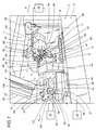
- -figure 1 shows a unit for feeding and applying seals to security cassettes for banknotes, embodied in accordance with the present invention, viewed schematically in perspective and in part as a block diagram, with certain parts omitted for clarity;
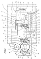
- -figure 2 shows the unit of figure 1 in a schematic plan view;
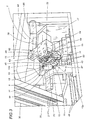
- -figure 3 shows the unit of figure 1 in the course of a different operating step;
- -figures 4 and 5 show a detail of figure 1 in two different operating steps, viewed schematically in a front elevation from the standpoint denoted A in figure 1, with certain parts omitted and others in section;
- -figure 6 shows the unit of figure 1 in a schematic side elevation from the standpoint denoted B;
- -figure 7 shows the unit of figure 1 in a schematic front elevation from the standpoint denoted C;
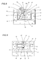
- -figures 8 and 9 are views taken from the same standpoint as in figure 7, showing the front of a cassette with the relative seal in two different operating positions;
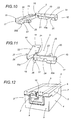
- -figures 10 and 11 show the seal in perspective;
- -figure 12 shows a cassette furnished with the respective seal, viewed in perspective.
-
- Referring to figures 1, 2 and 3 of the drawings, 1 denotes a unit, in its entirety, for feeding and applying
seals 2 tosecurity cassettes 3 containing banknotes. - As illustrated in figure 12, in particular, the
single cassette 3 is substantially parallelepiped in appearance, with a predominating longitudinal axis A, and comprises acontainer 4, also alid 5 associated pivotably with thecontainer 4 by way of ahinge 6 disposed transversely to the axis A and coinciding with arear face 7 of thecassette 3. - The
lid 5 can be locked in the position which closes thecontainer 4 through the agency of aremovable fastening mechanism 8 associated with afront face 9 of thecassette 3 opposite to therear face 7. - The
fastening mechanism 8, which is of familiar embodiment and illustrated in figures 3, 6, 8, 9 and 12, consists essentially in aplate 10 by which thelid 5 is retained in its closed position on thecontainer 4, affording twoslots 11 arranged in such a way that when thecassette 3 is closed and theplate 10 in the retaining position, they will accommodate twolugs 12 integral respectively with thelid 5 and with thecontainer 4. The portions of thelugs 12 that project from theplate 10 afford respective throughholes 13 withaxes 13a disposed transversely to the longitudinal axis A of the cassette. - As illustrated to advantage in figures 10 and 11, the
single seal 2 comprises twoparts flat box elements hinge 18. - Each
box element hinge 18, denoted 19 and 19a in the case of the onepart 14 and denoted 20 and 20a in the case of theother part 15. In particular, the walls denoted 19 and 20 lie substantially within one common plane, and the walls denoted 19a and 20a lie substantially within another common plane. - In addition, one
box element 16 presents a first pair of smaller side walls disposed parallel to thehinge 18, constituting theinternal flank face 21 and theexternal flank face 22 of therespective part 14, whilst theother box element 17 presents a second pair of smaller side walls disposed parallel to thehinge 18, likewise constituting theinternal flank face 23 and theexternal flank face 24 of therespective part 15, the internal flank faces 21 and 23 being the two faces that are drawn together when theseal 2 is closed. - One
internal flank face 23 presents ahook 25 positioned to snap non-releasably into asocket 26 afforded by theother flank face 21 and thus render theseal 2 unopenable, that is to say, the seal can be opened only by being broken. In addition, the external flank faces 22 and 24 present respectivecurved teeth 27 positioned near thehinge 18, shown to advantage in the perspective view of figure 11, constituting latch means 28 which at the moment of closing theseal 2 are inserted into the respective throughholes 13 of the twolugs 12, these in turn constituting receiving means for the latch means 28 associated with theseal 2. - The
unit 1 comprises amagazine 29 in which theseals 2 are loaded, with aframe 30 of turret type embodiment aligned, as illustrated advantageously in figure 6, on a respectivelongitudinal axis 31 inclined at a predetermined angle from the vertical and affording twostacking channels 32 occupied by theseals 2, diametrically opposed relative to theaxis 31 of the frame as illustrated in figure 2. - The
magazine 29 is equipped withdrive means 33, at the base, by which the twostacking channels 32 are set in rotation about thelongitudinal axis 31 and placed cyclically with therespective outlet 34 aligned on astation 35 from which theseals 2 are dispensed. Also operating at thissame dispensing station 35 are means 36 by which to pick up and transfer theseals 2, and these together with themagazine 29 constitute feed means denoted 37 in their entirety. - Referring to figures 2 and 6, the drive means 33 of the
magazine 29 comprise agear wheel 38 coaxial with thelongitudinal axis 31 of theframe 30, and apinion 39 keyed to theshaft 40 of amotor 41 rigidly associated with theselfsame frame 30. - As discernible in particular from figures 1, 2 and 3, the pickup and transfer means 36 comprise a
clamp assembly 42 consisting in first andsecond jaws pedestal 45 and capable of movement one relative to another. In particular, thefirst jaw 43 is mounted transversely to the end of anarm 45a on which thesecond jaw 44 is carried slidably, capable of movement relative to thefirst jaw 43 back and forth as indicated by the arrows denoted F, brought about by respective drive means of conventional embodiment, not illustrated. Thepedestal 45 is mounted to aslide 46 set in motion by respective pneumatic means also of conventional embodiment, denoted schematically by ablock 47, moving on a pair ofways 48 carried by aframe 77 of theunit 1 and aligned along a predetermined longitudinal path P parallel to the direction of the arrows F. - Accordingly, the
clamp assembly 42 is capable of movement along the aforementioned path P, carried by theslide 46, between thedispensing station 35, at which theseals 2 are taken up singly from themagazine 29 by thejaws seal 2 is released ultimately to gripping and positioning means denoted 49 in their entirety. - As indicated in figures 1 to 5, the
first jaw 43 presents twopins 50 and thesecond jaw 44 presents twopins 51. Observing figures 4 and 5 it will be seen that thepins respective axes 52 parallel to theaxis 31 of the magazine, set in motion by conventional actuator means denoted 53 in figures 4 and 5. - The
pins clamp assembly 42 in a plane lying at right angles to theaxis 31 of themagazine 29, and an extended position proud of the selfsame plane, illustrated in figures 2, 3 and 4. - The gripping and positioning means 49 comprise a
gripper head 54 which in turn comprises a pair ofarms 55 mounted by way of two first ends associated with a drive mechanism, described in due course, torespective pivots 56 carried by the free end of thehead 54 and rotatable aboutrespective axes 57. The free end of eacharm 55, opposite to the first end, affords aseat 58 serving to receive one of the twoparts seal 2. Thesingle seat 58 presents a U profile and is created by the free end of thearm 55 in combination with an angle element denoted 59. The free end of thearm 55 is equipped with arespective actuator 60, indicated by phantom lines in figure 5, of which therelative plunger 61 is designed to penetrate theseat 58 and operate in conjunction with theangle element 59, engaging and pinning thewalls box elements respective parts single seal 2. - As discernible from figures 3 to 7, the
gripper head 54 is mounted to the free end of anarm 62, coupled by its remaining end to ashaft 63 which is carried in asleeve 78 secured to theframe 77 and can thus be made to rock about anaxis 64 extending parallel to theways 48 of theslide 46, through the agency of acylinder 65 of which the rod is connected to alever 66 coupled to the end of theshaft 63 remote from thearm 62. As illustrated to advantage in figure 6, thegripper head 54 is made by thecylinder 65 to alternate between a receiving position coinciding with the release position of theclamp assembly 42, as illustrated in figures 3, 4 and 5, in which theseals 2 are taken up, and a final operating position illustrated in figures 6 and 7, in which thegripper head 54 lies adjacent and parallel to thefront face 9 of acassette 3 and the latch means 28 of theseal 2 are offered to the receiving means of the fastening mechanism. - As illustrated in figures 3, 4 and 5, the two
pins 50 of thefirst jaw 43 and the twopins 51 of thesecond jaw 44 constitute locating elements that can be disposed, at thedispensing station 35 of themagazine 29, in such a way that when extended from the plane occupied by the face of theclamp assembly 42, and as thejaws opposite flank faces first part 14 and the opposite flank faces 23 and 24 of thesecond part 15 of theseal 2. More exactly, theclamp assembly 42 and thepins first means 67 of gripping theseals 2. - Observing figures 1, 2, 4, 5 and 7 in particular, the
gripper head 54, which together with the pair ofarms 55 constitutes second gripping means 68, is equipped with respective drive means 69 that serve to operate thearms 55, these in turn constituting means 70 by which the twoparts seal 2 are coupled and providing the aforementioned drive mechanism associated with thearms 55. - The drive means 69 comprise a pair of
gears 71 keyed to thepivots 56 of therespective arms 55 and engaged in meshing contact one with the other. In particular, as shown in figure 2, eachgear 71 presents acircular toothed portion 71a and aflat portion 71b to which the aforementioned first end of therelative arm 55 is fixed, the twotoothed portions 71a being in constant mesh. - As discernible from figures 1, 3, 4 and 5, the drive means 69 further comprise a
toothed sector 72 keyed to one of the twopivots 56 and thus rigidly associated with therelative gear 71. Thesector 72 engages in meshing contact with arack 73 connected to anactuator 74, indicated in figures 2 and 7, by which theselfsame rack 73 can be reciprocated in the direction of the arrow denoted F1 between two limit positions: a first in which thearms 55 are spread as illustrated in figure 1, in readiness to receive theseal 2, and a second in which the twoparts seal 2 are brought together. On assuming the final operating position in which thesingle seal 2 is applied, thegripper head 54 lies adjacent to and parallel with thefront face 9 of acassette 3, as illustrated by phantom lines in figure 6 and by solid lines in figure 7. - In operation, departing from the situation of figure 2 in which the
outlet 34 of one of the twostacking channels 32 is aligned on thedispensing station 35, theclamp assembly 42 is translated by theslide 46 along the path P up to theselfsame station 35, with the first andsecond jaws respective pins jaws - In this way the
jaws walls seal 2 occupying theoutlet 34 of themagazine 29. - At this juncture the two pairs of
pins block 75 in figure 1, whilst the twojaws pins part seal 2, with the result that the seal remains clamped. - The
slide 46 is now traversed along theways 48 by the relativepneumatic means 47, following the predetermined path P, to the point of drawing into alignment with thegripper head 54 and gathering the ends of the twoparts seal 2 in theseats 58 afforded by the free ends of the twoarms 55, currently in the spread position and ready to receive as shown in figures 3 and 4. Once in this position, as illustrated in figure 5, thepins seal 2 and theplungers 61 made to extend by therelative actuators 60, which are connected to a source of compressed air denoted schematically by ablock 76 in figure 1, thus clamping the twoparts seal 2 against theangle elements 59. - Thereupon, the
clamp assembly 42 returns to thedispensing station 35 while thegripper head 54 is rotated about theaxis 64 of theshaft 63 by thecylinder 65 in such a way as to direct thehead 54 against thefront face 9 of thecassette 3, with the result that theseal 2, still held by the twoarms 55, is positioned in contact with theplate 10 of thefastening mechanism 8. - The
rack 73 is now caused by theactuator 74 to shift in the direction denoted F1, and thetoothed sector 72 with which it engages in mesh induces thepivot 56 and thecorresponding gear 71 to rotate in the direction denoted F2, or clockwise as observed in figure 7, causing the othermeshing gear 71 to rotate in the opposite direction denoted F3. This causes the free ends of the twoarms 55 to rotate toward one another, and as a result of thearms 55 thus drawing together, the twoparts seal 2 are caused to rotate about thehinge 18, the two internal flank faces 21 and 23 are brought together, thehook 25 locates in thesocket 26 and thecurved teeth 27 will locate simultaneously in the respective throughholes 13 of thelugs 12, as illustrated sequentially in figures 8 and 9. - Following the application of the
seal 2 to thecassette 3, theplungers 61 retract, releasing therespective parts seal 2, the twoarms 55 resume the spread position and thegripper head 54 is rotated back to the position distanced from theface 9 of thecassette 3, at the end of the aforementioned path P, in readiness to receive afurther seal 2 from theclamp assembly 42.
Claims (12)
- A unit for feeding and applying seals (2) to security cassettes (3) for banknotes, wherein the cassette comprises a container (4) and a lid (5), the seal is composed of at least two parts (14, 15) affording respective latch means (28) designed to engage relative receiving means (12, 13) afforded both by the container (4) and by the lid (5), and the parts (14, 15) of the seal (2) are designed to couple together non-releasably and manoeuvrable from an open condition to a closed condition in which the cassette (3) is secured through the agency of the latch means (28),
characterized
in that it comprises feed means (37) by which the seals (2) are handled in the open condition, also means (49) by which the seals (2) are gripped and positioned alongside the receiving means (12, 13) in an operating position, and means (70) by which the two parts (14, 15) of the seal (2) are coupled together in such a way as to bring about the closed condition. - A unit as in claim 1, wherein the feed means (37) comprise means (36) by which the seals (2) are picked up from a dispensing station (35) and transferred to the gripping and positioning means (49).
- A unit as in claim 2, wherein the pickup and transfer means (36) comprise respective first gripping means (67) designed to clamp the seals (2) by engaging first predetermined portions (21, 22; 23, 24) of the two parts (14, 15), and the gripping and positioning means (49) comprise second gripping means (68) designed to take up and clamp the seals (2) by engaging second predetermined portions (19, 19a; 20, 20a) of the two parts (14, 15).
- A unit as in claim 2, wherein the feed means (37) comprise a magazine (29) containing the seals (2) and presenting at least one outlet (34) coinciding with the station (35) from which the seals (2) are dispensed to the pickup and transfer means (36).
- A unit as in claim 3, wherein the first gripping means (67) include a clamp assembly (42) positionable at the station (35) from which the seals (2) are dispensed, capable of movement along a predetermined path (P) between the dispensing station (35) and the gripping and positioning means (49) in such a way as to release the seals (2) to the second gripping means (68), and comprising two jaws (43, 44) capable of movement one relative to another between a non-operative open position and a closed operating position of engagement with the first predetermined portions (21, 22; 23, 24) of the seal (2).
- A unit as in claim 5 for feeding and applying a seal (2) of which the two parts (14, 15) are connected one to another by way of a hinge (18) and appear as respective flat box elements (16, 17) compassed by larger side walls (19, 19a; 20, 20a) occupying respective common planes disposed transversely to the hinge (18), and smaller side walls or flank faces (21, 22; 23, 24) parallel to the hinge (18), wherein the jaws (43, 44) of the clamp assembly (42) comprise respective locating elements (50, 51) positionable parallel with the hinge (18) of the seal (2), when at the dispensing station (35), in such a manner as to enter into contact with the first predetermined portions of the opposite flank faces (21, 22; 23, 24) presented by the two parts (14, 15) of the seal during the relative movement of the jaws (43, 44) toward the closed operating position.
- A unit as in claim 5 or 6, wherein the locating elements (50, 51) comprise at least two pins (50,
51) associated respectively with each jaw (43, 44), capable of movement between a position of non-interference with the seal (2) and an operating position of readiness to enter into contact with the first predetermined portions of the opposite flank faces (21, 22; 23, 24) presented by the two parts (14, 15) of the seal (2). - A unit as in claim 5, wherein the second gripping means (68) comprise a gripper head (54) equipped with a pair of arms (55) affording the means (70) by which the two parts (14, 15) of the seal (2) are coupled together, each individual arm (55) mounted pivotably by a first end to the gripper head (54) and presenting a seat (58) at the opposite end in which to receive a respective free end presented by a corresponding flat box element (16, 17) of the seal (2), each seat (58) equipped with respective means (60, 61) by which to clamp the free end of the relative flat box element (16, 17).
- A unit as in claim 8, wherein the second gripping means (68) are capable of oscillating movement about an axis (64) of rotation parallel to the predetermined path (P) between a position in which the seals (2) are received from the clamp assembly (42), and a final operating position in which the seal (2) is offered to the receiving means (12, 13) associated with the container (4) and the lid (5) of a security cassette (3).
- A unit as in claim 8 or 9, wherein the gripper head (54) comprises drive means (69) by which the arms (55) are caused to rotate about respective pivot axes (56), with the second gripping means (68) in the final operating position, between the spread position in which the seal (2) is received, and a closed position in which the two parts (14, 15) of the seal (2) are brought together and coupled thus non-releasably with the respective latch means (28) engaging the respective receiving means (12, 13).
- A unit as in claim 4, wherein the magazine (29) comprises a turret type frame (30) aligned on a longitudinal axis (31) and presenting at least two channels (32) along which the seals (2) are stacked parallel to the longitudinal axis (31), also drive means (33) by which the frame (30) is rotated about the longitudinal axis (31) so as to position the outlet (34) of each channel (32) cyclically at the station (35) from which the seals (2) are dispensed to the pickup and transfer means (36).
- A unit as in claim 11, wherein the longitudinal axis (31) of the magazine (29) is inclined from the vertical by a predetermined angle.
Applications Claiming Priority (2)
| Application Number | Priority Date | Filing Date | Title |
|---|---|---|---|
| IT2000BO000057A IT1321209B1 (en) | 2000-02-09 | 2000-02-09 | UNIT FOR FEEDING AND APPLICATION OF SEAL ELEMENTS IN CASE FOR BANKNOTES. |
| ITBO000057 | 2000-02-09 |
Publications (1)
| Publication Number | Publication Date |
|---|---|
| EP1123866A2 true EP1123866A2 (en) | 2001-08-16 |
Family
ID=11438153
Family Applications (1)
| Application Number | Title | Priority Date | Filing Date |
|---|---|---|---|
| EP01830073A Withdrawn EP1123866A2 (en) | 2000-02-09 | 2001-02-06 | A unit for feeding and applying seals to security cassettes for banknotes |
Country Status (3)
| Country | Link |
|---|---|
| US (1) | US6536500B2 (en) |
| EP (1) | EP1123866A2 (en) |
| IT (1) | IT1321209B1 (en) |
Families Citing this family (3)
| Publication number | Priority date | Publication date | Assignee | Title |
|---|---|---|---|---|
| WO2003046845A2 (en) * | 2001-11-23 | 2003-06-05 | De La Rue International Limited | Method for depositing items of value |
| US20040260034A1 (en) * | 2003-06-19 | 2004-12-23 | Haile William Alston | Water-dispersible fibers and fibrous articles |
| EP3467245B1 (en) * | 2017-10-09 | 2023-01-25 | Peter Villiger | Safety cassette, assembly with a safety cassette and method for handling paper money |
Family Cites Families (9)
| Publication number | Priority date | Publication date | Assignee | Title |
|---|---|---|---|---|
| GB2039264B (en) * | 1978-12-08 | 1983-09-28 | De La Rue Crosfield | Security cassettes |
| GB2105399A (en) * | 1981-07-04 | 1983-03-23 | Woodward Roger Clive | Security box or cabinet |
| US5161736A (en) * | 1991-06-24 | 1992-11-10 | Bloomfield Manufacturing Co. | Locking currency stacker apparatus and method |
| WO1994005885A1 (en) * | 1992-08-28 | 1994-03-17 | Jens Herman Martin | Improvements in and relating to security |
| GB2291116B (en) * | 1994-06-24 | 1997-04-30 | Chiltern Retail Systems Limite | Improvements relating to cash cassettes |
| US5533316A (en) * | 1995-05-04 | 1996-07-09 | Self Industries, Inc. | Apparatus for compressing and positioning the sealing components of an open head drum |
| US5715923A (en) * | 1996-01-16 | 1998-02-10 | Rowe International, Inc. | Currency acceptor with locking cash box |
| AUPO617097A0 (en) * | 1997-04-09 | 1997-05-08 | Harcor Security Seals Pty Limited | Security seal |
| IT1320884B1 (en) * | 2000-02-21 | 2003-12-10 | Gd Spa | DEVICE FOR MANEUVERING A BOX CLOSING ORGAN |
-
2000
- 2000-02-09 IT IT2000BO000057A patent/IT1321209B1/en active
-
2001
- 2001-02-06 EP EP01830073A patent/EP1123866A2/en not_active Withdrawn
- 2001-02-09 US US09/779,581 patent/US6536500B2/en not_active Expired - Fee Related
Also Published As
| Publication number | Publication date |
|---|---|
| IT1321209B1 (en) | 2003-12-31 |
| ITBO20000057A1 (en) | 2001-08-09 |
| US20020026986A1 (en) | 2002-03-07 |
| US6536500B2 (en) | 2003-03-25 |
Similar Documents
| Publication | Publication Date | Title |
|---|---|---|
| EP0420560B1 (en) | Leaf paper bundling apparatus | |
| EP0793198A3 (en) | Bill handling machine | |
| US4406728A (en) | Apparatus for binding articles with tape | |
| US5244082A (en) | Apparatus for remodelling multi-purpose container holder | |
| US6536500B2 (en) | Unit for feeding and applying seals to security cassettes for banknotes | |
| JP6908673B2 (en) | Automatic banknote handling system and automatic banknote handling method | |
| US8307862B2 (en) | Bag loader | |
| KR200403281Y1 (en) | Palletizer for a grain filled bag | |
| US6536307B1 (en) | Device for operating a cashbox closure mechanism | |
| JPH04303320A (en) | Workpiece delivery device | |
| JP2735982B2 (en) | Bag opening holding device in bag packing machine | |
| JP2602447Y2 (en) | Structure of bound paper sheets for paper sheet processing machine | |
| JPH05278704A (en) | Bag mouth bundling device in bag packing machine | |
| JP2000296803A (en) | Automatic bagging device for can lid | |
| JPS59174491A (en) | Vessel conveyor and elevator system | |
| JPH0225784Y2 (en) | ||
| JPS6226067B2 (en) | ||
| JPH0834410A (en) | Concentrator binding device | |
| JP2583342Y2 (en) | Device for holding and transporting paper sheets in a paper binding machine | |
| JPH0215473B2 (en) | ||
| JPS62109722A (en) | Sheets stacking bundling device | |
| JPH07151656A (en) | Product sampler | |
| FR2853626A1 (en) | Package machine for producing cigarette packet, has transmission device to displace container along closed path extending across unloading position for extracting pile of additional packaging components | |
| FR2813063A1 (en) | Banknote packing machinery includes plastic film thermoformer producing shells and lidding station sealing second film over shells filled with wads of notes | |
| JPS60205439A (en) | Opener for x-ray film cassette |
Legal Events
| Date | Code | Title | Description |
|---|---|---|---|
| PUAI | Public reference made under article 153(3) epc to a published international application that has entered the european phase |
Free format text: ORIGINAL CODE: 0009012 |
|
| AK | Designated contracting states |
Kind code of ref document: A2 Designated state(s): AT BE CH CY DE DK ES FI FR GB GR IE IT LI LU MC NL PT SE TR |
|
| AX | Request for extension of the european patent |
Free format text: AL;LT;LV;MK;RO;SI |
|
| RAP1 | Party data changed (applicant data changed or rights of an application transferred) |
Owner name: CURRENCY SYSTEMS INTERNATIONAL, INC. |
|
| STAA | Information on the status of an ep patent application or granted ep patent |
Free format text: STATUS: THE APPLICATION IS DEEMED TO BE WITHDRAWN |
|
| 18D | Application deemed to be withdrawn |
Effective date: 20030903 |