EP1123139B1 - Flexible respirator filter - Google Patents
Flexible respirator filter Download PDFInfo
- Publication number
- EP1123139B1 EP1123139B1 EP99970939A EP99970939A EP1123139B1 EP 1123139 B1 EP1123139 B1 EP 1123139B1 EP 99970939 A EP99970939 A EP 99970939A EP 99970939 A EP99970939 A EP 99970939A EP 1123139 B1 EP1123139 B1 EP 1123139B1
- Authority
- EP
- European Patent Office
- Prior art keywords
- filter
- flexible
- frame
- connector
- filter material
- Prior art date
- Legal status (The legal status is an assumption and is not a legal conclusion. Google has not performed a legal analysis and makes no representation as to the accuracy of the status listed.)
- Expired - Lifetime
Links
- 239000000463 material Substances 0.000 claims abstract description 38
- 230000002093 peripheral effect Effects 0.000 claims abstract description 9
- 230000001681 protective effect Effects 0.000 abstract description 3
- 229920002457 flexible plastic Polymers 0.000 abstract 1
- 238000009434 installation Methods 0.000 description 5
- 230000029058 respiratory gaseous exchange Effects 0.000 description 4
- 239000003570 air Substances 0.000 description 3
- 238000003466 welding Methods 0.000 description 3
- OKTJSMMVPCPJKN-UHFFFAOYSA-N Carbon Chemical compound [C] OKTJSMMVPCPJKN-UHFFFAOYSA-N 0.000 description 2
- 238000005452 bending Methods 0.000 description 2
- 239000012080 ambient air Substances 0.000 description 1
- 239000003517 fume Substances 0.000 description 1
- 239000007789 gas Substances 0.000 description 1
- 239000002184 metal Substances 0.000 description 1
- 230000001473 noxious effect Effects 0.000 description 1
- 210000002345 respiratory system Anatomy 0.000 description 1
- 125000006850 spacer group Chemical group 0.000 description 1
- -1 vapors Substances 0.000 description 1
Images


Classifications
-
- A—HUMAN NECESSITIES
- A62—LIFE-SAVING; FIRE-FIGHTING
- A62B—DEVICES, APPARATUS OR METHODS FOR LIFE-SAVING
- A62B23/00—Filters for breathing-protection purposes
- A62B23/02—Filters for breathing-protection purposes for respirators
Definitions
- the present invention relates to a respirator filter and, more particularly, to a flexible respirator filter which can be attached easily to a respirator mask without being damaged or crushed.
- Respirator masks equipped with detachable filters have been used for decades to protect the respiratory system of individuals from noxious gases, vapors, fumes and particulates.
- the detachable filters are connected to the inlet valves of the respirator mask through which ambient air is drawn as the user inhales. As such, the air is filtered before it is inhaled.
- respirator filter cartridges are designed as short cylindrical containers having a rigid metal or plastic shell with a filter material such as activated carbon housed inside the container. See e . g ., U.S. Patent No. 5,714,126. Due to their rigid shell design, such filter cartridges are inflexible, and if they are thick enough, they sometimes make it difficult for the user to wear certain eye and face protection such as a welding hood. Additionally, sometimes such filter cartridges are thick enough to interfere with a portion of the users vision. In an attempt to overcome these limitations in certain applications where only a particulate filter is required, flexible particulate filters have been designed that easily fit under certain eye and face protection such as a faceshield.
- U.S. Patent No. Re. 35,062 shows a flexible particulate filter having front and back walls of filter material joined to each other along their peripheral edges in a spaced-apart relationship and equipped with a breather tube having an attachment means to secure the filter to a respirator mask.
- the spaced-apart relationship is maintained by a soft porous layer of specific materials encased within and substantially coextensive with the filter walls.
- the filter walls must be maintained in a spaced-apart relationship; otherwise the front and back walls would merely collapse together and the filter would not function. While such filters are flexible, their lack of a frame makes them susceptible to being damaged due to soiling and crushing, particularly during attachment and removal.
- the filter may become dirty or bent such that air cannot be drawn through a portion of the filter.
- the effective surface area of the filter is reduced and the breathing resistance increases.
- the porous layer contributes up to 50% of the total pressure drop of the filter making breathing more difficult.
- U.S. Patent No. 5,732,695 describes a particulate filter which is a hybrid between a flexible filter and a filter cartridge. It has the front and back walls of filter material like a flexible filter but also has a rigid frame having an outer peripheral band connected by a plurality of spacers to an inner breather tube. While this filter has the increased surface area of a flexible filter, the rigid frame prevents flexibility.
- the 75 FFP 100 particulate filter made by North Safety Products includes a flexible frame that may be described as having a hub and spokes.
- the hub of the frame forms a centrally located breather tube which attaches the filter to a respirator mask.
- the spokes of the frame separate the front and back layers of the filter.
- the hub and spoke design results in an interior frame having a sharp point and edges at the end of each spoke.
- a filter which has the benefits of a flexible particulate filter without the known limitations. This can be accomplished by utilizing a flexible internal frame that extends to the edge of the filter material and is substantially coextensive therewith, thereby providing sufficient rigidity to prevent crushing and damage to the filter during installation while still providing sufficient flexibility to enable the filter to fit under other personal protective equipment.
- US-A-2 205 368 discloses a filter having the pre-characterising features of claim 1.
- a flexible respirator filter comprising:
- the flexible frame is made from a flexible material such as plastic.
- the flexible frame could be made of a rigid material which is thin enough to be flexible. While the frame itself is flexible, having a peripheral edge adjacent to the sealed edge of the filter material can provide enough rigidity to prevent crushing during installation or removal while not being so rigid that the filter will not bend to fit under a welding mask or faceshield.
- the flexible frame is totally encased between the front and back layers of filter material and remains substantially coextensive with and immediately adjacent to the sealed peripheral edge of the filter material along substantially its entire length.
- the shape of the filter is maintained and crushing does not occur.
- the internal frame is generally round and does not have any corners or points so that when the user grasps the filter to install or remove it, the filter remains stiff and undamaged. Attachment is also aided by a plurality of finger recesses preferably formed in one side of the frame.
- the connector is for attaching the filter to a respirator mask.
- the connector protrudes through an opening in the back portion of filter material and is sealed thereto.
- the connector is formed integrally with the frame.
- the filter has a generally circular shape with the connector being slightly off-centre. By having the connector located slightly off-centre, the filter can be maintained in a swept back position when installed on a respirator mask thereby giving the user greater visibility when looking down.
- the finger recesses are formed integrally with the frame and are located on opposite sides of the connector.
- the flexible frame creates a plenum in the filter so that air entering the front and back portions of the filter material can easily reach an opening in the connector without any increase in breathing resistance.
- the frame has a plurality of cross-members, preferably at least one cross-member lying within the plane of the frame that acts as a stiffening element and several additional cross-members, which do not lie in the plane of the frame and thereby create the plenum, between the front and back portions of filter material which facilitates breathing through the filter.
- Figure 1 shows two flexible filters 1 attached to the facepiece 50 of a half-mask respirator 60.
- Figure 2 shows two filters 1 attached to the facepiece 70 of a full-face respirator 80.
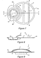
- Figure 3 shows a top or plan view of the front of a filter according to an embodiment of the present invention.
- Figure 4 shows a side view of the filter of Figure 3 such that the connector 10 protruding from the back of the filter can be seen.
- the filter 1 is generally circular in shape with a pair of recesses 9A and 9B which permit easy installation of the filter on the respirator facepiece without causing soiling and other damage to the filter.
- the connector 10 is located off-center of the filter such that the recesses 9A and 9B are on opposite sides of the connector 10.
- the swept-back design of the filter when attached to the respirator facepiece provides for improved vision and comfort. Its low profile and flexibility enable it to fit easily under a welding hood and with other personal protective equipment.
- a flexible filter 1 having a generally circular shape with a front portion of filter material 2, and a back portion of filter material 3 (shown in Figures 4 and 6).
- the back portion of filter material 3 has an opening 15 through which a connector 10 having an opening 18 therethrough extends.
- the front portion 2 is sealed to the back portion 3 by any of several means known to one skilled in the art. Preferably ultrasonic bonding is used along the periphery of the filter material to create a sealed edge 30.
- a flexible frame 4 Enclosed within, but preferably not connected to, the filter material is a flexible frame 4.
- the flexible frame 4 has substantially the same shape as the filter material with dimensions slightly smaller than the dimensions of the filter material.
- the frame 4 is encased like a glove between front layer 2 and back layer 3 and has a perimeter 16 which is preferably located immediately adjacent to the sealed edge 30 of the filter material. Additionally, the frame has a plurality of cross-members 5, 6 and 7. As shown in Figures 6 and 8, cross-member 5 spans the frame and lies within the plane of the perimeter 16. Cross-members 6 and 7 are located on opposite sides of cross-member 5 and rise above the plane of the frame 4 creating the plenum 17 between front portion 2 and back portion 3.
- connector 10 is preferably formed integrally with the flexible frame 4, has an opening 18 therein and has a bayonet-type connector 11 for attaching the filter 1 to the respirator mask.
- the connector 10 has a circular shape with a diameter much smaller than that of frame 4.
- the connector 10 extends below the plane of the frame and preferably is offset from the center of the frame's 4 circular shape. The connector 10 could even lie on, or beyond, the circumference of the frame 4.
- the outer end of the connector 10 opposite the plenum 17 is adapted to be detachably connected to a respirator mask, preferably in a single orientation by a keyed bayonet connector 11.
- the back portion of filter material 3 has an opening 15 through which the connector 10 extends.
- the back portion of filter material 3 is sealed to connector 10 preferably by ultrasonic bonding so that the connector 10 provides a closed passageway for airflow from the plenum space to the inlet valve of the respirator mask.
- finger tabs 9A and 9B located on either side of the connector 10 which aid in the installation of the flexible filter.
- the recesses 9A and 9B are preferably formed integrally with the frame 4 and lie within the plane of the frame 4.
- the user grips the filter 1 placing his fingers in recesses 9A and 9B, places the bayonet connector tabs into the respirator mask's keyed receiving slots and slowly turns the filter approximately thirty degrees (30°) until the bayonet connector 11 snaps in place. Removal of the filter 1 is accomplished by using the recesses 9A and 9B to grip and twist the filter in the opposite direction so that bayonet connector 11 disengages.
- replacement and changeout of the filter 1 can be easily accomplished without bending, crushing, or damaging.
- the filter described herein preferably has a generally circular shape and utilizes a bayonet type connector, the invention is not limited to only these embodiments.
- the invention may be practiced with filters of any shape or with any type of connector.
Landscapes
- Health & Medical Sciences (AREA)
- General Health & Medical Sciences (AREA)
- Business, Economics & Management (AREA)
- Emergency Management (AREA)
- Respiratory Apparatuses And Protective Means (AREA)
- Filtering Of Dispersed Particles In Gases (AREA)
Abstract
Description
Claims (9)
- A flexible respirator filter (1) comprising:characterised in that a flexible frame (4) is encased between the front (2) and back (3) portions, the flexible frame (4) defining a plenum (17) which is accessible through the connector (10; 11), and wherein the flexible frame (4) has a peripheral edge (16) that extends to the sealed edge of the filter material (30) and is substantially coextensive therewith.a flexible filter material forming substantially coextensive front and back portions (2 and 3), the front and back portions being sealed to each other along their periphery forming a sealed edge (30); anda connector (10; 11) which protrudes through the back portion (3) of the flexible filter material and is sealed thereto,
- The flexible filter according to claim 1, further characterised in that the filter material comprises a plurality of layers.
- The flexible filter according to claim 1 or 2, further characterised in that the connector (11) is formed integrally with the flexible frame (4).
- The flexible filter according to claim 1, 2 or 3, further characterised in that the flexible frame includes a plurality of flexible cross-members (5,6,7), one of which (5) lies in a plane of the flexible frame peripheral edge (16) and another of which (6; 7) extends out of the plane toward the filter material.
- The flexible filter according to claim 4 further characterised in that there are three flexible cross members (5,6,7) which span the flexible frame (4), wherein a middle cross member (5) and the flexible frame peripheral edge (16) lie in one plane and both outer cross members (6,7) include a portion lying outside of the plane thereby forming the plenum (17) between the front (2) and back (3) portions of the filter material.
- The flexible filter according to claim 4, further characterised in that the flexible frame (4) includes a plurality of recesses (9A, 9B) for grasping the filter.
- The flexible filter according to claim 6, further characterised in that there are two recesses (9A, 9B) which are located on opposite sides of the connector (11).
- The flexible filter according to any preceding claim, wherein the filter is generally circular in shape and the connector (10; 11) is located off-centre.
- The flexible filter according to any preceding claim, wherein the connector (11) is a bayonet type such that the filter (1) can be attached to a respirator in only one orientation.
Applications Claiming Priority (5)
| Application Number | Priority Date | Filing Date | Title |
|---|---|---|---|
| US10537698P | 1998-10-23 | 1998-10-23 | |
| US105376P | 1998-10-23 | ||
| US217165 | 1998-12-21 | ||
| US09/217,165 US6345620B2 (en) | 1998-10-23 | 1998-12-21 | Flexible respirator filter |
| PCT/US1999/024687 WO2000024469A1 (en) | 1998-10-23 | 1999-10-21 | Flexible respirator filter |
Publications (3)
| Publication Number | Publication Date |
|---|---|
| EP1123139A1 EP1123139A1 (en) | 2001-08-16 |
| EP1123139A4 EP1123139A4 (en) | 2002-05-22 |
| EP1123139B1 true EP1123139B1 (en) | 2003-11-19 |
Family
ID=26802512
Family Applications (1)
| Application Number | Title | Priority Date | Filing Date |
|---|---|---|---|
| EP99970939A Expired - Lifetime EP1123139B1 (en) | 1998-10-23 | 1999-10-21 | Flexible respirator filter |
Country Status (9)
| Country | Link |
|---|---|
| US (1) | US6345620B2 (en) |
| EP (1) | EP1123139B1 (en) |
| JP (1) | JP2002528195A (en) |
| CN (1) | CN1132640C (en) |
| AT (1) | ATE254490T1 (en) |
| AU (1) | AU753999B2 (en) |
| BR (1) | BR9914719A (en) |
| DE (1) | DE69912981T2 (en) |
| WO (1) | WO2000024469A1 (en) |
Cited By (1)
| Publication number | Priority date | Publication date | Assignee | Title |
|---|---|---|---|---|
| KR20160000419U (en) * | 2013-06-04 | 2016-02-03 | 베이징 윈써니 하모니 사이언스 앤드 테크놀로지 컴퍼니 리미티드 | Air filter assembly and nasal air filtering device |
Families Citing this family (36)
| Publication number | Priority date | Publication date | Assignee | Title |
|---|---|---|---|---|
| WO2002013946A2 (en) * | 2000-08-17 | 2002-02-21 | Vase Technology | Bi/multi-directional filter cartridge and filter platform for mounting the cartridge thereon |
| USD467656S1 (en) | 2001-06-25 | 2002-12-24 | 3M Innovative Properties Company | Respirator facemask |
| USD471627S1 (en) | 2001-06-25 | 2003-03-11 | 3M Innovative Properties Company | Respirator facemask assembly |
| US6736138B2 (en) * | 2001-11-10 | 2004-05-18 | Amad Tayebi | Seamless pad-type filter |
| US7334579B2 (en) * | 2001-11-10 | 2008-02-26 | Amad Tayebi | Low resistance to flow filter |
| RU2214295C1 (en) * | 2002-09-09 | 2003-10-20 | Закрытое акционерное общество "Сорбент-Центр Внедрение" | Respirator |
| US7152600B2 (en) * | 2003-01-22 | 2006-12-26 | Biokidz Usa Nfp | Biohazard mask suitable for civilians |
| US20050145249A1 (en) * | 2003-12-31 | 2005-07-07 | Solyntjes Alan J. | Personal respiratory protection device that has a permanent or semi-permanent bayonet connection |
| US7320722B2 (en) * | 2004-10-29 | 2008-01-22 | 3M Innovative Properties Company | Respiratory protection device that has rapid threaded clean air source attachment |
| US20060254592A1 (en) * | 2005-01-28 | 2006-11-16 | Bruce Anders | Respiratory mask |
| US20080083411A1 (en) * | 2006-10-06 | 2008-04-10 | Steven Lyon Guth | Self-Sterilizing Particulate Respirator Facepiece and Method for Using Same |
| DE102007023959B3 (en) * | 2007-05-23 | 2008-08-21 | Dräger Safety AG & Co. KGaA | Filter for respiratory device , comprises anterior and posterior filter mates, flexible frame arranged between the mates, and filter connection at a first end piece of the frame and with a second end piece at opposite end of the frame |
| US8839788B2 (en) * | 2007-08-31 | 2014-09-23 | 3M Innovative Properties Company | Respirator attachment component with molded thermoset elastomeric seal |
| KR200453432Y1 (en) | 2009-07-17 | 2011-05-02 | 정정대 | Filter for dust mask |
| US8984753B2 (en) * | 2010-05-20 | 2015-03-24 | 3M Innovative Properties Company | Method of making filter cartridge having roll-based housing sidewall |
| US8460423B2 (en) | 2010-05-20 | 2013-06-11 | 3M Innovative Properties Company | Filter cartridge having central plenum and housing sidewall |
| US8887719B2 (en) | 2011-12-15 | 2014-11-18 | 3M Innovative Properties Company | Air filtration device having tuned air distribution system |
| US8899227B2 (en) | 2011-12-15 | 2014-12-02 | 3M Innovative Properties Company | Air filtration device having subsections lacking fluid communication |
| US9950202B2 (en) | 2013-02-01 | 2018-04-24 | 3M Innovative Properties Company | Respirator negative pressure fit check devices and methods |
| US9510626B2 (en) | 2013-02-01 | 2016-12-06 | 3M Innovative Properties Company | Sleeve-fit respirator cartridge |
| US11052268B2 (en) | 2013-02-01 | 2021-07-06 | 3M Innovative Properties Company | Respirator negative pressure fit check devices and methods |
| USD786443S1 (en) | 2015-02-27 | 2017-05-09 | 3M Innovative Properties Company | Filter element |
| USD792959S1 (en) | 2015-02-27 | 2017-07-25 | 3M Innovative Properties Company | Filter element having a pattern |
| USD779674S1 (en) | 2015-02-27 | 2017-02-21 | 3M Innovative Properties Company | Filter element having a connector |
| AU2016223087B2 (en) * | 2015-02-27 | 2019-01-03 | 3M Innovative Properties Company | Flexible filter element having an end outlet |
| USD842982S1 (en) | 2016-03-28 | 2019-03-12 | 3M Innovative Properties Company | Hardhat suspension adapter for half facepiece respirators |
| EP3436161A4 (en) | 2016-03-28 | 2020-01-22 | 3M Innovative Properties Company | SUSPENSION FASTENER FOR HEADGEAR |
| USD816209S1 (en) | 2016-03-28 | 2018-04-24 | 3M Innovative Properties Company | Respirator inlet port connection seal |
| EP4364818B1 (en) | 2016-03-28 | 2025-10-29 | 3M Innovative Properties Company | Respiratory protection device |
| JP6850812B6 (en) | 2016-03-28 | 2021-04-28 | スリーエム イノベイティブ プロパティズ カンパニー | Sealing device and method for multi-chamber breathing mask |
| USD827810S1 (en) | 2016-03-28 | 2018-09-04 | 3M Innovative Properties Company | Hardhat suspension adapter for half facepiece respirators |
| AU2020218002A1 (en) * | 2019-02-06 | 2021-08-19 | CleanSpace IP Pty Ltd | Tight fitting respirator with exhalation filter and exhalation filter for tight fitting respirator |
| KR102179117B1 (en) * | 2020-01-30 | 2020-11-16 | 윤영환 | Respiration mask |
| US12478281B2 (en) | 2020-07-10 | 2025-11-25 | Jeffrey Mitchell | Instantaneous olfactory disease detection system and method of use of detection |
| EP4304740A4 (en) | 2021-03-10 | 2025-04-02 | Milwaukee Electric Tool Corporation | REUSABLE RESPIRATOR |
| US11872416B1 (en) * | 2023-03-14 | 2024-01-16 | Moldex-Metric, Inc. | Filter and method |
Family Cites Families (8)
| Publication number | Priority date | Publication date | Assignee | Title |
|---|---|---|---|---|
| US2142064A (en) * | 1937-05-29 | 1938-12-27 | Robert Malcom | Respirator |
| US2205368A (en) * | 1937-10-30 | 1940-06-18 | Robert Malcom | Respirator |
| US2295119A (en) * | 1941-01-02 | 1942-09-08 | Malcom | Respirator |
| US4886058A (en) * | 1988-05-17 | 1989-12-12 | Minnesota Mining And Manufacturing Company | Filter element |
| AU4858496A (en) | 1995-01-27 | 1996-08-14 | Mine Safety Appliances Company | Respirator filter system |
| US5732695A (en) * | 1997-03-11 | 1998-03-31 | Parmelee Industries | Respirator filtration device |
| US6044842A (en) * | 1997-05-19 | 2000-04-04 | Pereira; Michael | Gasketless connecting adapter |
| US5992414A (en) * | 1997-08-26 | 1999-11-30 | Mine Safety Appliances Company | Respirator filter |
-
1998
- 1998-12-21 US US09/217,165 patent/US6345620B2/en not_active Expired - Lifetime
-
1999
- 1999-10-21 WO PCT/US1999/024687 patent/WO2000024469A1/en not_active Ceased
- 1999-10-21 CN CN998124621A patent/CN1132640C/en not_active Expired - Fee Related
- 1999-10-21 AU AU14492/00A patent/AU753999B2/en not_active Ceased
- 1999-10-21 AT AT99970939T patent/ATE254490T1/en not_active IP Right Cessation
- 1999-10-21 JP JP2000578070A patent/JP2002528195A/en active Pending
- 1999-10-21 EP EP99970939A patent/EP1123139B1/en not_active Expired - Lifetime
- 1999-10-21 BR BR9914719-0A patent/BR9914719A/en not_active IP Right Cessation
- 1999-10-21 DE DE69912981T patent/DE69912981T2/en not_active Expired - Lifetime
Cited By (2)
| Publication number | Priority date | Publication date | Assignee | Title |
|---|---|---|---|---|
| KR20160000419U (en) * | 2013-06-04 | 2016-02-03 | 베이징 윈써니 하모니 사이언스 앤드 테크놀로지 컴퍼니 리미티드 | Air filter assembly and nasal air filtering device |
| KR200486654Y1 (en) * | 2013-06-04 | 2018-06-18 | 베이징 윈써니 하모니 사이언스 앤드 테크놀로지 컴퍼니 리미티드 | Air filter assembly and nasal air filtering device |
Also Published As
| Publication number | Publication date |
|---|---|
| CN1132640C (en) | 2003-12-31 |
| US6345620B2 (en) | 2002-02-12 |
| WO2000024469A1 (en) | 2000-05-04 |
| US20010054424A1 (en) | 2001-12-27 |
| EP1123139A1 (en) | 2001-08-16 |
| CN1326370A (en) | 2001-12-12 |
| AU753999B2 (en) | 2002-10-31 |
| ATE254490T1 (en) | 2003-12-15 |
| BR9914719A (en) | 2001-11-06 |
| DE69912981T2 (en) | 2004-11-11 |
| AU1449200A (en) | 2000-05-15 |
| DE69912981D1 (en) | 2003-12-24 |
| JP2002528195A (en) | 2002-09-03 |
| EP1123139A4 (en) | 2002-05-22 |
Similar Documents
| Publication | Publication Date | Title |
|---|---|---|
| AU753999B2 (en) | Flexible respirator filter | |
| US6055983A (en) | Respirator filtration device | |
| EP2457617B1 (en) | Respiratory protection device | |
| US6793702B2 (en) | Filter cartridge platform and filter cartridge for use on the platform | |
| US5080094A (en) | Face mask | |
| KR101435234B1 (en) | Small size breathing protective device arranged to be held in the users mouth | |
| US6161540A (en) | Respirator filter having a pleated filter layer | |
| US5094236A (en) | Face mask | |
| US4856508A (en) | Face mask | |
| US6684882B1 (en) | Respirator | |
| US6467481B1 (en) | Stackable filter device | |
| KR20100017288A (en) | Maintenance-free flat-fold respirator that includes a graspable tab | |
| US5957131A (en) | Biological warfare mask | |
| US4080664A (en) | Welder's hood with air filter | |
| US5992414A (en) | Respirator filter | |
| US20060137689A1 (en) | Breathing protective device | |
| CN107405512B (en) | Flexible filter element with end outlet | |
| US2910979A (en) | Canisterless gas mask | |
| EP0149590A2 (en) | Protective respirator | |
| GB2045093A (en) | Respirator | |
| GB2329128A (en) | Nose clip for a respiratory mask | |
| ZA200102810B (en) | Flexible respirator filter. | |
| EP3735143B1 (en) | Helmet, especially full face helmet | |
| KR200279519Y1 (en) | Half face gas mask of directed type | |
| CN216022745U (en) | Self-rescue breathing device for fire |
Legal Events
| Date | Code | Title | Description |
|---|---|---|---|
| PUAI | Public reference made under article 153(3) epc to a published international application that has entered the european phase |
Free format text: ORIGINAL CODE: 0009012 |
|
| 17P | Request for examination filed |
Effective date: 20010521 |
|
| AK | Designated contracting states |
Kind code of ref document: A1 Designated state(s): AT BE CH CY DE DK ES FI FR GB GR IE IT LI LU MC NL PT SE |
|
| AX | Request for extension of the european patent |
Free format text: AL;LT;LV;MK;RO;SI |
|
| A4 | Supplementary search report drawn up and despatched |
Effective date: 20020410 |
|
| RIC1 | Information provided on ipc code assigned before grant |
Free format text: 7A 62B 7/10 A, 7A 62B 18/08 B, 7A 62B 23/02 B |
|
| 17Q | First examination report despatched |
Effective date: 20020719 |
|
| GRAH | Despatch of communication of intention to grant a patent |
Free format text: ORIGINAL CODE: EPIDOS IGRA |
|
| GRAS | Grant fee paid |
Free format text: ORIGINAL CODE: EPIDOSNIGR3 |
|
| GRAA | (expected) grant |
Free format text: ORIGINAL CODE: 0009210 |
|
| AK | Designated contracting states |
Kind code of ref document: B1 Designated state(s): AT BE CH CY DE DK ES FI FR GB GR IE IT LI LU MC NL PT SE |
|
| PG25 | Lapsed in a contracting state [announced via postgrant information from national office to epo] |
Ref country code: NL Free format text: LAPSE BECAUSE OF FAILURE TO SUBMIT A TRANSLATION OF THE DESCRIPTION OR TO PAY THE FEE WITHIN THE PRESCRIBED TIME-LIMIT Effective date: 20031119 Ref country code: LI Free format text: LAPSE BECAUSE OF FAILURE TO SUBMIT A TRANSLATION OF THE DESCRIPTION OR TO PAY THE FEE WITHIN THE PRESCRIBED TIME-LIMIT Effective date: 20031119 Ref country code: IT Free format text: LAPSE BECAUSE OF FAILURE TO SUBMIT A TRANSLATION OF THE DESCRIPTION OR TO PAY THE FEE WITHIN THE PRESCRIBED TIME-LIMIT;WARNING: LAPSES OF ITALIAN PATENTS WITH EFFECTIVE DATE BEFORE 2007 MAY HAVE OCCURRED AT ANY TIME BEFORE 2007. THE CORRECT EFFECTIVE DATE MAY BE DIFFERENT FROM THE ONE RECORDED. Effective date: 20031119 Ref country code: FI Free format text: LAPSE BECAUSE OF FAILURE TO SUBMIT A TRANSLATION OF THE DESCRIPTION OR TO PAY THE FEE WITHIN THE PRESCRIBED TIME-LIMIT Effective date: 20031119 Ref country code: CY Free format text: LAPSE BECAUSE OF FAILURE TO SUBMIT A TRANSLATION OF THE DESCRIPTION OR TO PAY THE FEE WITHIN THE PRESCRIBED TIME-LIMIT Effective date: 20031119 Ref country code: CH Free format text: LAPSE BECAUSE OF FAILURE TO SUBMIT A TRANSLATION OF THE DESCRIPTION OR TO PAY THE FEE WITHIN THE PRESCRIBED TIME-LIMIT Effective date: 20031119 Ref country code: BE Free format text: LAPSE BECAUSE OF FAILURE TO SUBMIT A TRANSLATION OF THE DESCRIPTION OR TO PAY THE FEE WITHIN THE PRESCRIBED TIME-LIMIT Effective date: 20031119 Ref country code: AT Free format text: LAPSE BECAUSE OF FAILURE TO SUBMIT A TRANSLATION OF THE DESCRIPTION OR TO PAY THE FEE WITHIN THE PRESCRIBED TIME-LIMIT Effective date: 20031119 |
|
| REG | Reference to a national code |
Ref country code: GB Ref legal event code: FG4D |
|
| REG | Reference to a national code |
Ref country code: CH Ref legal event code: EP |
|
| REF | Corresponds to: |
Ref document number: 69912981 Country of ref document: DE Date of ref document: 20031224 Kind code of ref document: P |
|
| REG | Reference to a national code |
Ref country code: IE Ref legal event code: FG4D |
|
| PG25 | Lapsed in a contracting state [announced via postgrant information from national office to epo] |
Ref country code: SE Free format text: LAPSE BECAUSE OF FAILURE TO SUBMIT A TRANSLATION OF THE DESCRIPTION OR TO PAY THE FEE WITHIN THE PRESCRIBED TIME-LIMIT Effective date: 20040219 Ref country code: GR Free format text: LAPSE BECAUSE OF FAILURE TO SUBMIT A TRANSLATION OF THE DESCRIPTION OR TO PAY THE FEE WITHIN THE PRESCRIBED TIME-LIMIT Effective date: 20040219 Ref country code: DK Free format text: LAPSE BECAUSE OF FAILURE TO SUBMIT A TRANSLATION OF THE DESCRIPTION OR TO PAY THE FEE WITHIN THE PRESCRIBED TIME-LIMIT Effective date: 20040219 |
|
| PG25 | Lapsed in a contracting state [announced via postgrant information from national office to epo] |
Ref country code: ES Free format text: LAPSE BECAUSE OF FAILURE TO SUBMIT A TRANSLATION OF THE DESCRIPTION OR TO PAY THE FEE WITHIN THE PRESCRIBED TIME-LIMIT Effective date: 20040302 |
|
| NLV1 | Nl: lapsed or annulled due to failure to fulfill the requirements of art. 29p and 29m of the patents act | ||
| REG | Reference to a national code |
Ref country code: CH Ref legal event code: PL |
|
| ET | Fr: translation filed | ||
| PLBE | No opposition filed within time limit |
Free format text: ORIGINAL CODE: 0009261 |
|
| STAA | Information on the status of an ep patent application or granted ep patent |
Free format text: STATUS: NO OPPOSITION FILED WITHIN TIME LIMIT |
|
| PG25 | Lapsed in a contracting state [announced via postgrant information from national office to epo] |
Ref country code: LU Free format text: LAPSE BECAUSE OF NON-PAYMENT OF DUE FEES Effective date: 20041021 Ref country code: IE Free format text: LAPSE BECAUSE OF NON-PAYMENT OF DUE FEES Effective date: 20041021 |
|
| PG25 | Lapsed in a contracting state [announced via postgrant information from national office to epo] |
Ref country code: MC Free format text: LAPSE BECAUSE OF NON-PAYMENT OF DUE FEES Effective date: 20041031 |
|
| 26N | No opposition filed |
Effective date: 20040820 |
|
| REG | Reference to a national code |
Ref country code: IE Ref legal event code: MM4A |
|
| PG25 | Lapsed in a contracting state [announced via postgrant information from national office to epo] |
Ref country code: PT Free format text: LAPSE BECAUSE OF NON-PAYMENT OF DUE FEES Effective date: 20040419 |
|
| PGFP | Annual fee paid to national office [announced via postgrant information from national office to epo] |
Ref country code: FR Payment date: 20121018 Year of fee payment: 14 Ref country code: DE Payment date: 20121017 Year of fee payment: 14 |
|
| PGFP | Annual fee paid to national office [announced via postgrant information from national office to epo] |
Ref country code: GB Payment date: 20121017 Year of fee payment: 14 |
|
| GBPC | Gb: european patent ceased through non-payment of renewal fee |
Effective date: 20131021 |
|
| REG | Reference to a national code |
Ref country code: DE Ref legal event code: R119 Ref document number: 69912981 Country of ref document: DE Effective date: 20140501 |
|
| PG25 | Lapsed in a contracting state [announced via postgrant information from national office to epo] |
Ref country code: GB Free format text: LAPSE BECAUSE OF NON-PAYMENT OF DUE FEES Effective date: 20131021 |
|
| REG | Reference to a national code |
Ref country code: FR Ref legal event code: ST Effective date: 20140630 |
|
| PG25 | Lapsed in a contracting state [announced via postgrant information from national office to epo] |
Ref country code: FR Free format text: LAPSE BECAUSE OF NON-PAYMENT OF DUE FEES Effective date: 20131031 Ref country code: DE Free format text: LAPSE BECAUSE OF NON-PAYMENT OF DUE FEES Effective date: 20140501 |