EP1122892A2 - Wireless communication apparatus and transmission power control method thereof - Google Patents
Wireless communication apparatus and transmission power control method thereof Download PDFInfo
- Publication number
- EP1122892A2 EP1122892A2 EP01100904A EP01100904A EP1122892A2 EP 1122892 A2 EP1122892 A2 EP 1122892A2 EP 01100904 A EP01100904 A EP 01100904A EP 01100904 A EP01100904 A EP 01100904A EP 1122892 A2 EP1122892 A2 EP 1122892A2
- Authority
- EP
- European Patent Office
- Prior art keywords
- transmission power
- control
- unit
- station
- power control
- Prior art date
- Legal status (The legal status is an assumption and is not a legal conclusion. Google has not performed a legal analysis and makes no representation as to the accuracy of the status listed.)
- Granted
Links
Images


Classifications
-
- H—ELECTRICITY
- H04—ELECTRIC COMMUNICATION TECHNIQUE
- H04W—WIRELESS COMMUNICATION NETWORKS
- H04W52/00—Power management, e.g. Transmission Power Control [TPC] or power classes
- H04W52/04—Transmission power control [TPC]
- H04W52/18—TPC being performed according to specific parameters
- H04W52/26—TPC being performed according to specific parameters using transmission rate or quality of service QoS [Quality of Service]
- H04W52/265—TPC being performed according to specific parameters using transmission rate or quality of service QoS [Quality of Service] taking into account the quality of service QoS
-
- H—ELECTRICITY
- H03—ELECTRONIC CIRCUITRY
- H03G—CONTROL OF AMPLIFICATION
- H03G3/00—Gain control in amplifiers or frequency changers
- H03G3/20—Automatic control
- H03G3/30—Automatic control in amplifiers having semiconductor devices
- H03G3/3036—Automatic control in amplifiers having semiconductor devices in high-frequency amplifiers or in frequency-changers
- H03G3/3042—Automatic control in amplifiers having semiconductor devices in high-frequency amplifiers or in frequency-changers in modulators, frequency-changers, transmitters or power amplifiers
-
- H—ELECTRICITY
- H04—ELECTRIC COMMUNICATION TECHNIQUE
- H04W—WIRELESS COMMUNICATION NETWORKS
- H04W52/00—Power management, e.g. Transmission Power Control [TPC] or power classes
- H04W52/04—Transmission power control [TPC]
- H04W52/18—TPC being performed according to specific parameters
- H04W52/26—TPC being performed according to specific parameters using transmission rate or quality of service QoS [Quality of Service]
- H04W52/267—TPC being performed according to specific parameters using transmission rate or quality of service QoS [Quality of Service] taking into account the information rate
-
- H—ELECTRICITY
- H04—ELECTRIC COMMUNICATION TECHNIQUE
- H04W—WIRELESS COMMUNICATION NETWORKS
- H04W52/00—Power management, e.g. Transmission Power Control [TPC] or power classes
- H04W52/04—Transmission power control [TPC]
- H04W52/30—Transmission power control [TPC] using constraints in the total amount of available transmission power
- H04W52/36—Transmission power control [TPC] using constraints in the total amount of available transmission power with a discrete range or set of values, e.g. step size, ramping or offsets
-
- H—ELECTRICITY
- H04—ELECTRIC COMMUNICATION TECHNIQUE
- H04W—WIRELESS COMMUNICATION NETWORKS
- H04W52/00—Power management, e.g. Transmission Power Control [TPC] or power classes
- H04W52/04—Transmission power control [TPC]
- H04W52/30—Transmission power control [TPC] using constraints in the total amount of available transmission power
- H04W52/36—Transmission power control [TPC] using constraints in the total amount of available transmission power with a discrete range or set of values, e.g. step size, ramping or offsets
- H04W52/367—Power values between minimum and maximum limits, e.g. dynamic range
-
- H—ELECTRICITY
- H04—ELECTRIC COMMUNICATION TECHNIQUE
- H04W—WIRELESS COMMUNICATION NETWORKS
- H04W52/00—Power management, e.g. Transmission Power Control [TPC] or power classes
- H04W52/04—Transmission power control [TPC]
- H04W52/54—Signalisation aspects of the TPC commands, e.g. frame structure
- H04W52/60—Signalisation aspects of the TPC commands, e.g. frame structure using different transmission rates for TPC commands
-
- H—ELECTRICITY
- H04—ELECTRIC COMMUNICATION TECHNIQUE
- H04W—WIRELESS COMMUNICATION NETWORKS
- H04W52/00—Power management, e.g. Transmission Power Control [TPC] or power classes
- H04W52/04—Transmission power control [TPC]
- H04W52/06—TPC algorithms
- H04W52/08—Closed loop power control
-
- H—ELECTRICITY
- H04—ELECTRIC COMMUNICATION TECHNIQUE
- H04W—WIRELESS COMMUNICATION NETWORKS
- H04W52/00—Power management, e.g. Transmission Power Control [TPC] or power classes
- H04W52/04—Transmission power control [TPC]
- H04W52/18—TPC being performed according to specific parameters
- H04W52/20—TPC being performed according to specific parameters using error rate
Definitions
- the present invention relates to a wireless communication apparatus used in such a mobile communication system that a mobile communication is carried out by employing a portable telephone and the like. More specifically, the present invention is directed to a wireless communication apparatus used in a transmitter, and a transmission power control method executed between a mobile station and a base station in a mobile communication system.
- transmission power control techniques are known in such a mobile communication system with employment of a portable telephone and the like. That is, in this mobile communication system, while information is transferred, transmission power of the own mobile station is controlled in response to a distance between a base station and the mobile station so as to maintain constant electric power of a signal reached to the base station.
- the transmission power control techniques are capable of reducing interference occurred between communication channels and are capable of improving frequency utilization efficiencies.
- a CDMA (Code Division Multiple Access) type mobile communication system using the spread spectrum technique corresponding to one sort of multiple access type communication systems for multiplexing a plurality of communication channels, a single frequency band is commonly used by a plurality of users.
- a so-called “near-far problem” may occur, namely one communication signal having low electric power may be masked by another communication signal having high electric power. Therefore, the following problem may occur. That is, a communication signal of another communication station may deteriorate as an interference signal wave line quality of the own communication station.
- various transmission power control techniques have been conventionally investigated, or considered.
- the transmission power control systems capable of following interference signals which are instantaneously varied, such a transmission power control system constituted by a closed loop is known in this technical field.
- the high-linearity transmission power control with the wide dynamic range for example, 70 to 80 dB
- the high precision of transmission power while the high power transmission is carried out is required in the wide-band CDMA (W-CDMA etc.) communication system in IMT-2000, so that the transmission power control is required in higher precision.
- W-CDMA etc. wide-band CDMA
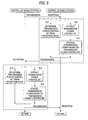
- Fig. 5 is a flow chart for describing one example of the conventional transmission power control method realized by the closed loop.
- the base station determines a transmission power control bit based upon reception power of a reception signal wave (namely, desirable signal wave) sent from the mobile station (step S11).
- the base station inserts this determined transmission power control bit into a transmission signal, and then, transmits this resultant transmission signal to the mobile station.
- the mobile station receives the signal transmitted from the base station, and extracts the transmission power control bit from the received signal (step S15) , and then, controls a variable power amplifier employed in the own mobile station in response to the instruction of this transmission power control bit so as to change the transmission power (step S16).
- the mobile station determines a transmission power control bit based upon reception power of a reception signal wave (namely, desirable signal wave) sent from the base station (step S14) .
- the mobile station inserts this determined transmission power control bit into a transmission signal, and then, transmits this resultant transmission signal to the base station.
- the base station receives the signal transmitted from the mobile station, and extracts the transmission power control bit from the received signal (step S12), and then, controls a variable power amplifier employed in the own base station in response to the instruction of this transmission power control bit so as to change the transmission power (step S13).
- the reception power in the base station and also the reception power in the mobile station can be kept substantially constant irrespective of locations of the mobile station.
- the transmission power control range corresponding to the value (1 unit) of the transmission power control bit is required to be reduced.
- the transmission power control range is decreased, then the rapid, or sudden variation of the reception power cannot be followed by this conventional transmission power control method. As a result, there is such a problem that the precision of the transmission power control operation is deteriorated.
- variable power amplifier operable in the high precision is necessarily required.
- variable power amplifier must be controlled in high precision.
- the circuit scale is increased, so that the power consumption amount thereof is increased and further, the wireless communication apparatus becomes bulky in size, resulting in deteriorations of portabilities thereof.
- the present invention has been made to solve the above-described problems, and therefore, has an object to provide both a wireless communication apparatus and a transmission power control method, while a transmission power control operation can be carried out in high precision with employment of a simple arrangement, and the wireless communication apparatus can be made compact and operable under low power consumption.
- a wireless communication apparatus is featured by such a wireless communication apparatus having a transmission power control function used to control transmission power of the own communication station by employing a transmission power control bit sent from a communication counter station to the own communication station, comprising a control period changing unit which changes a control period of the transmission power control bit.
- the wireless communication apparatus further comprises a transmission power control range changing unit which changes a transmission power control range corresponding to the transmission power control bit.
- the wireless communication apparatus further comprises: a condition detecting unit which detects either a condition of the own communication station or a condition of the communication counter station; and the control period changing unit changes the control period based upon the detected condition.
- the wireless communication apparatus further comprises: a condition detecting unit which detects either a condition of the own communication station or a condition of the communication counter station; the control period changing unit changes the control period based upon the detected condition; and the transmission power control range changing unit changes the transmission power control range based upon the detected condition.
- a wireless communication apparatus is featured by that in a wireless communication apparatus equipped with first and second power amplifiers for amplifying transmission power transmitted from the own communication station to the communication counter station, and having a transmission power control function used to control the transmission power, the wireless communication apparatus comprises: a power amplification control unit which controls a gain of the first power amplifier; a matching unit which performs a matching operation of a characteristic of the second power amplifier; and a matching control unit which controls the matching unit.
- the wireless communication apparatus further comprises: a transmission power detecting unit which detects transmission power of the own communication station; a transmission power correcting unit which corrects the detected transmission power in response to a communication condition of the own communication station; and an error calculating unit which calculates an error between said corrected transmission power and target transmission power, wherein both the power amplification control unit and the matching control unit execute the control operations thereof based upon the calculated error.
- the wireless communication apparatus further comprises: an error selecting unit which selects an error occurred in an effective control section from the plurality of errors which are calculated over a plurality of control sections; and both the power amplification control unit and the matching control unit execute the control operations based upon the selected error.
- the wireless communication apparatus further comprises: an error averaging unit which averages the selected error; and both the power amplification control unit and the matching control unit execute the control operations based upon the averaged error.
- the wireless communication apparatus further comprises: a correction amount calculating unit which calculates a correction amount based upon the error; and a correction amount limiting unit which limits the calculated correction amount; and both the power amplification control unit and the matching control unit execute the control operations based upon the limited correction amount.
- a transmission power control method for controlling transmission power of the own communication station by employing a transmission power control bit which is sent from a counter communication station to the own communication station, comprising: control period changing step which changes a control period of the transmission power control bit.
- the transmission power control method further comprises: a transmission power control range changing step which changes a transmission power control range corresponding to the transmission power control bit.
- the transmission power control method further comprises: a condition detecting step which detects either a condition of the own station or a condition of the communication counter station; and the control period changing step changes the control period based upon the detected condition.
- the transmission power control method further comprises: a condition detecting step which detects either a condition of the own station or a condition of the communication counter station; and the control period changing step changes the control period based upon the detected condition; and the transmission power control range changing step changes the transmission power control range based upon the detected condition.
- a transmission power control method in which transmission power transmitted from the own communication station to a counter communication station is controlled by way of a first power amplifier and a second power amplifier, comprising: a gain control step which controls a gain of the first power amplifier; a matching step which matches a characteristic of the second power amplifier by way of a matching circuit; and a matching control step which controls the matching circuit.
- the transmission power control method further comprises: a transmission power detecting step which detects transmission power of the own communication station; a transmission power correcting step which corrects the detected transmission power in response to a communication condition of the own communication station; and an error calculating step which calculates an error between the corrected transmission power and target transmission power, wherein both the power amplification control step and the matching control step execute the control operations thereof based upon the calculated error.
- the transmission power control method further comprises an error selecting step which selects an error occurred in an effective control section from the plurality of errors which are calculated over a plurality of control sections, wherein both the power amplification control step and the matching control step execute the control operations based upon the selected error.
- the transmission power control method further comprises an error averaging step for averaging the selected error, wherein both the power amplification control step and the matching control step execute the control operations based upon the averaged error.
- the transmission power control method further comprises: a correction amount calculating step which calculates a correction amount based upon the error; and a correction amount limiting step which limits the calculated correction amount, wherein both the power amplification control step and the matching control step execute the control operations based upon the limited correction amount.
- the control period of the transmission power control bit is changed.
- the transmission power control range corresponding to the transmission power control bit is changed in connection with the change of the control period.
- both the control period and the transmission power control range are changed in response to either the communication condition of the own communication station or the communication condition of the counter communication station.
- the transmission power control range is reduced so as to control the transmission power in high precision
- the transmission power can be followed also with respect to the sudden change in the reception power, and thus, the control precision of the transmission power can be improved.
- the transmission power control operation can be carried out in high precision by using the simple arrangement.
- the apparatus construction such as the variable power amplifier can be made compact, and furthermore, the low power consumption can be realized.
- the transmission power is controlled by both the first power amplifier and the second power amplifier, which amplify the transmission power transmitted from the own communication station to the counter communication station
- the gain of the first power amplifier is controlled, and also, the matching circuit for matching the characteristic of the second power amplifier is controlled.
- the transmission power of the own communication station is detected, and the detected transmission power is corrected in accordance with the communication condition of the own station. While the calculation is made of the error between the corrected transmission power and the target transmission power, both the gain and the matching circuit are controlled based upon the calculated error.
- such an error occurred in the effective control section is selected from a plurality of errors which are calculated over a plurality of control sections, and then, both the gain and the matching circuit are controlled based upon the selected error. Furthermore, the selected errors are averaged, and then, both the gain and the control circuit are controlled based upon the averaged error. Moreover, while the correction amount is calculated based on the error, the calculated correction amount is limited. Thus, both the gain and the matching circuit are controlled based on this limited correction amount.
- both the gain of the variable power amplifier functioning as the first power amplifier and also the matching operation of the characteristic of the semi-fixed power amplifier functioning as the second power amplifier can be controlled, so that the transmission power control operation can be carried out in higher precision.
- the transmission power control operation can be carried out in high precision by using the simple arrangement, so that the apparatus construction such as the variable power amplifier can be made compact, and furthermore, the low power consumption can be realized.
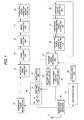
- Fig. 1 is a block diagram for showing an arrangement of a major unit of a wireless communication apparatus according to an embodiment of the present invention.
- Fig. 2 is a flow chart for describing a sequential operation of a transmission power control method.
- Fig. 3 is a flow chart for describing a sequential operation of a transmission power amplification control operation executed in a mobile station.
- Fig. 4 is a flow chart for explaining a sequential operation of the transmission power amplification control operation executed in the mobile station, which is continued to that of Fig. 3.
- Fig. 5 is a flow chart for explaining one method of the conventional transmission power control method by the closed loop.
- Fig. 1 is a block diagram for indicating an arrangement of a major unit of a wireless communication apparatus according to an embodiment of the present invention.
- the wireless communication apparatus is provided in a mobile communication appliance which constitutes, for instance, either a base station or a mobile station of a cellular communication system.
- This wireless communication apparatus power-amplifies a signal containing transfer information, and then transmits the power-amplified signal to a communication counter party.
- a transmission power control method as described in this specification is suitably applied especially to such a case that while a high linearity is maintained over a wide power control range, a transmission power control operation should be carried out in high precision, as required in such a mobile terminal as a base station and a portable telephone in a CDMA type mobile communication system.
- the wireless communication apparatus of this embodiment may be applied not only to a mobile communication appliance, but also other wireless communication apparatuses which require transmission power control operations similar to the above-described transmission power control operation.
- This example represents only such an arrangement related to the transmission power control of the wireless communication apparatus.
- an arrangement related to other process operations is omitted (for instance, circuits and key inputs related to spreading, despreading, coding, decoding, telephone calling, telephone receiving, and controlling operations are omitted in a CDMA type portable telephone).
- the wireless communication apparatus is arranged by containing an antenna 11 for transmitting/receiving a wireless signal, and a transmission/reception separator 12 for separating a transmission signal from a reception signal and vice versa.
- the wireless communication apparatus is arranged by including a wireless reception unit 31, a demodulating unit 29 for converting a reception signal into a baseband signal, and a baseband signal processing unit 25 for performing a signal processing operation and a signal decoding operation of a received baseband signal.
- the wireless reception unit 31 is provided with a high frequency amplifying circuit, a local oscillating circuit, an IF signal amplifying circuit, and the like, by which a reception signal is high-frequency-amplified, and also, this high-frequency-amplified signal is frequency-converted into an intermediate frequency (IF) signal.
- a high frequency amplifying circuit a local oscillating circuit, an IF signal amplifying circuit, and the like, by which a reception signal is high-frequency-amplified, and also, this high-frequency-amplified signal is frequency-converted into an intermediate frequency (IF) signal.
- IF intermediate frequency
- this wireless communication apparatus is arranged by containing the above-explained baseband signal processing unit 25, a modulating unit 22, and a wireless transmission unit 30.
- the baseband signal processing unit 25 executes a signal processing operation, and a signal coding operation of a baseband signal to be transmitted.
- the modulating unit 22 modulates a transmission signal and then converts the modulated transmission signal into an IF (intermediate frequency) signal.
- the wireless transmission unit 30 power-amplifies the transmission signal, and frequency-converts the power-amplified transmission signal into an RF-band (radio frequency band) signal.
- This wireless transmission unit 30 contains a variable power amplifier 19, a power amplifier 20, and a matching circuit 21.
- the power amplifier 20 power-amplifies the transmission signal by a semi-fixed gain.
- the matching circuit 21 executes matching operations with respect to a gain, a current consumption, a noise characteristic, and a distortion characteristic of the power amplifier 20.
- the wireless communication apparatus includes the above-explained baseband signal processing unit 25, the variable power amplifier 19, the power amplifier 20, and the matching circuit 21, and also a variable power amplification control unit 24, a condition change detecting unit 28, a transmission power control bit controlling unit 26, and a transmission power control period controlling unit 27.
- the variable power amplification control unit 24 i.e., power amplification controlling means controls the gain of this variable power amplifier 19 so as to perform a transmission power control operation.
- the condition change detecting unit 28 detects a communication condition change of a communication counter station and a communication condition change of the own communication station from a reception signal wave of the communication counter station outputted from the baseband signal processing unit 25 and also a communication condition of the own communication station.
- the transmission power control bit controlling unit 26 i.e., transmission power control range changing means
- the transmission power control period controlling unit 27 i.e., control period changing means
- the wireless communication apparatus contains a transmission power detecting unit 13, a detection power correcting unit 14, an error calculating unit 15, an error selecting unit 16, an error averaging unit 17, a transmission power correction amount limiting unit 18, and a matching circuit control unit 23.
- the transmission power detecting unit 13 i.e., transmission power detecting means
- the detection power correcting unit 14 i.e., transmission power correcting means
- the error calculating unit 15 calculates an error between the transmission power corrected by this detection power correcting unit 14 and target transmission power.
- the error selecting unit 16 selects an error of an effective control section from a plurality of errors which are outputted from this error calculating unit 15 over a plurality of control sections.
- the error averaging unit 17 i.e., error averaging means
- the transmission power correction amount limiting unit 18 calculates a correction amount with respect to the target transmission power, and also limits the calculated correction amount.
- the matching circuit control unit 23 controls the matching circuit 21 based upon the limited correction amount.
- the condition change detecting unit 28 detects both a condition change of a base station and a change of an own station from the reception signal wave of the base station and the communication conditions of the own station, which are outputted from the baseband signal processing unit 25.
- both the transmission power control period controlling unit 27 and the transmission power control bit controlling unit 26 change both the transmission power control period and the transmission power control range of the transmission power control bit based upon the output result of the condition change detecting unit 28.
- the baseband signal processing unit 25 determines a transmission power control bit based upon reception power of a reception signal wave (desirable signal wave) received from the base station, and then, inserts this determined transmission power control bit into the transmission signal.
- the transmission signal is modulated by the modulating unit 22, and the modulated transmission signal is frequency-converted into an IF-band transmission signal. Furthermore, this IF-band transmission signal is frequency-converted into an RF-band transmission signal, and thereafter, this RF-band transmission signal is transmitted via the transmission/reception separator 12 from the antenna 11 to the base station.
- the detected transmission signal is corrected by the detection power correcting unit 14, so that an error with respect to the target transmission power is calculated by the error calculating unit 15.
- the calculated error is selected by the error selecting unit 16 and averaged by the error averaging unit 17, and thereafter, the resultant error is limited by the transmission power correction amount limiting unit 18 so as to constitute a correction amount with respect to the target transmission power.
- a signal transmitted from the base station is received by the antenna 11, and then, this reception signal is entered via the transmission/reception separator 12 to the wireless reception unit 31.
- This reception signal is frequency-converted into an IF-band signal by the wireless reception unit 31, and this IF-band reception signal is converted into a baseband signal by the demodulating unit 29. Thereafter, this baseband signal is entered into the baseband signal processing unit 25.
- the baseband signal processing unit 25 extracts the transmission power control bit based upon the baseband signal outputted from the demodulating unit 29, and updates the target transmission power, and thereafter, corrects the target transmission power in accordance with the correction amount limited by the transmission power correction amount limiting unit 18. Then, both the variable power amplification control unit 24 and the matching circuit control unit 23 control the variable power amplifier 19 and the matching circuit 21 based upon the corrected target transmission power.
- Fig. 2 is a flow chart for describing the sequential operation of the transmission power control method.
- the base station determines a transmission power control bit based upon reception power of a reception signal wave (desirable signal wave) of the mobile station (S101) . Then, both a change in communication conditions of the own communication station and a change in communication conditions of the counter communication station are detected (S102), and both the control period of the transmission power control bit and the transmission power control range are changed based upon the changes in the detected communication conditions (S104 and S105). Thereafter, this transmission power control bit is inserted into the transmission signal, and then, the resultant transmission signal is transmitted to the mobile station.
- a reception signal wave desirable signal wave
- the mobile station receives a signal transmitted from the base station, and extracts a transmission power control bit from the received signal (S203). Then, the transmission power of the own station is controlled in response to an instruction of the extracted transmission power control bit (S206).
- the mobile station detects a change in communication conditions of the own station and also a change in communication conditions of the communication counter station based upon the reception signal wave of the base station and the communication condition of the own station, which are outputted from the baseband signal processing unit 25, namely, the reception power, the transmission power, the transmission power control bit, the change amount of the control condition, and the change speed (S202).
- the control period of the transmission power control bit is changed in response to this detection result (S204).
- the transmission power control period is shortened, the following precision of the transmission power with respect to the desirable power can be increased, whereas when the transmission power of the base station is wanted to be gently controlled, since the control period of the transmission power is prolonged, the following precision of the transmission power with respect to the desirable power can be increased.
- the precision of the transmission power control operation can be improved, as compared with the conventional method for fixing the control period of the transmission power.
- the mobile station changes the transmission power control range in response to the communication condition changes of the own station and also of the counter station detected at the step S202 (S205) .
- the mobile station changes the transmission power control range in response to the communication condition changes of the own station and also of the counter station detected at the step S202 (S205) .
- the transmission power of the base station is wanted to be rapidly controlled at the step S205 by the mobile station, since the transmission power control range is widened, the following precision of the transmission power with respect to the desirable power can be increased, whereas when the transmission power of the base station is wanted to be gently controlled, since the control range of the transmission power is narrowed, the following precision of the transmission power with respect to the desirable power can be increased. As a result, the precision of the transmission power control operation can be improved, as compared with the conventional method for fixing the control period of the transmission power.
- the control range of the transmission power is widened (increased) at the step S205, and further, the control period of the transmission power is shortened at the step S204, so that the control section of this transmission power control range is shortened.
- the mutual effect can be improved.
- a total number of calculations executed in the base station can be reduced, and the wireless communication apparatus can be made simpler, and can be operated under low power consumption.
- the control range of the transmission power is similarly narrowed (reduced) at the step S205, and further, the control period of the transmission power is prolonged at the step S204, so that the control section of this transmission power control range is prolonged.
- the mutual effect can be improved.
- the transmission power control resolution in the base station can be reduced, and the wireless communication apparatus can be made simpler, and can be operated under low power consumption.
- the mobile station determines a transmission power control bit from the reception signal wave (step S201), and inserts the determined transmission power control bit into the transmission signal, and thereafter, transmits the resultant transmission signal to the base station.
- the base station receives a signal transmitted from the mobile station and extracts the transmission power control bit from this reception signal (S103).
- the mobile station controls the transmission power of the own station (S106).
- both the transmission power control range and the control period with respect to the transmission power control bit are changed in response to the change in the communication conditions of the own station and also the change in the communication conditions of the counter station, the rapid variations in the reception power can be followed even when the transmission power control range is reduced, or narrowed so as to control the transmission power in high precision. As a consequence, the precision of the transmission power control operation can be improved.
- both the high-precision variable power amplifier and the high-precision variable power control unit are no longer required. Also, since the required transmission power can be minimized by improving such precision of the transmission power control operations realized in the base station and the mobile station, the wireless communication apparatus can be operated under low power consumption and can be made compact.
- Fig. 3 and Fig. 4 are flow charts for describing transmission power amplification control sequential operations executed in the mobile station. This amplification control of the transmission power is repeatedly carried out.
- this mobile station when the mobile station receives a signal transmitted from the base station, this mobile station extracts a transmission power control bit TPC [N] of the present execution (step S401), and then, updates a target value of transmission power (target transmission power) POW [N] of the own mobile station (step S402). Furthermore, the mobile station corrects the target value of the transmission power by adding the transmission power correction amount APCL [N-1] calculated at the step S312 during the preceding execution of the transmission power amplification control to this target transmission power POW [N] (step S403). Thus, this corrected target value is used as target transmission power POWA [N].
- the mobile station controls both the variable power amplifier 19 and the matching circuit 21 of the power amplifier 20 in accordance with this corrected target transmission power POWA [N] (steps S404 and S405).
- this mobile station since the mobile station controls the matching circuit 21 of the power amplifier 20, this mobile station is capable of varying the matching operations of the gain, the current consumption, the noise characteristic, and the distortion characteristic of the power amplifier 20.
- the mobile station since the mobile station controls the matching circuit 21 of the power amplifier 20 in response to the target transmission power POWA [N], the wireless communication apparatus can be operated under low power consumption, as compared with such a conventional method that the matching circuit is fixed.
- the matching circuit 21 may be controlled in such a manner that both the margin of the gain and the distortion characteristic are allocated to the reduction of the current consumption and the improvement of the noise characteristic.
- the matching circuit 21 may be controlled in such a manner that the spared portion of the noise characteristic is allocated to both the reduction of the current consumption and the improvement of the distortion characteristic.
- variable power amplifier can be made compact, the wireless communication apparatus can be made simple and also can be operated under low power consumption. This control operation may be applied not only to the amplification control of the transmission power, but also to the amplification control of the reception power.
- the mobile station detects transmission power PDET [N] of the own station (step S406), corrects this detected transmission power (detection power) PDET [N] in accordance with the communication condition of the own station in a proper manner (step S407), and then constitutes this corrected power as corrected detection power PDETC [N].
- the mobile station may properly correct the detection power in response to a temperature of the own communication station, a power supply voltage thereof, a transmission frequency thereof, a spreading rate of a transmission signal thereof, a code multiple number of the transmission signal thereof, and a peak value of transmission power thereof.
- the mobile station corrects the detected power PDET [N] in order to obtain constant detection power irrespective of various changes in the temperature of the own station, the power supply voltage thereof, the transmission frequency thereof, the spreading rate of the transmission signal thereof, the code multiple number of the transmission signal thereof, and also the peak value of the transmission power thereof, the detection precision of the transmission power can be increased, and also the control precision of the transmission power control operation can be increased.
- the mobile station may correct the detected power in response to environmental changes in a proper manner.
- the mobile station may correct the detection power PDET [N] in accordance with the environmental change. Therefore, the wireless communication apparatus can be made simple, and can be operated under low power consumption.
- the mobile station selects only such a power error ERR[N] in an effective control section of the detection power PDETC [N] to constitute this selected power error as a power error ERRS [N] .
- the mobile station averages the power errors ERRS [N] selected at the step S409 over the control section (step S410).
- the mobile station calculates an average value ERRA [N] in accordance with a move average formula shown in the below-mentioned formula (1), or an averaging formula with employment of a forget coefficient indicated in the below-mentioned formula (2) :
- ERRA[N] (ERRS[N] + ERRS[N-1] +, ..., + ERRS [N-M] ) / (M+1)
- ERRA[N] ERRS[N] X (1- ⁇ ) + ERRA[N-1] X ⁇
- the mobile station may correct the transmission power of the own station by employing the error ERRA [N] which is averaged over the control section at the step S410, so that the precision of the transmission power control operation can be improved.
- the mobile station calculates a transmission power correction amount APC [N] by employing the error ERRA [N] averaged at the step S410 (step S411), and then limits this transmission power correction amount APC [N] (step S412) to set this limited transmission power correction amount as a transmission power correction APCL [N].
- the transmission power correction amount APC [N] is equal to the error ERRA [N].
- the mobile station limits the transmission power correction amount in order that the control amount per 1 control operation does not exceed a limit value DAPC [dB] .
- the mobile station may set the limit value DAPC to be smaller than, or equal to 0.4 dB.
- the transmission power correction amount per 1 control is limited, the relative precision of the transmission power control operation can be increased, so that the precision of the transmission power control operation can be improved.
- the transmission power control range is reduced so as to control the transmission power in high precision
- the transmission power can be followed also with respect to the sudden change in the reception power, and thus, the control precision of the transmission power can be improved.
- both the gain of the variable power amplifier functioning as the first power amplifier and also the matching operation of the characteristic of the semi-fixed power amplifier functioning as the second power amplifier can be controlled, so that the transmission power control operation can be carried out in higher precision.
- the transmission power control operation can be carried out in high precision by using the simple arrangement, so that the apparatus construction such as the variable power amplifier can be made compact, and furthermore, the low power consumption can be realized.
- the transmission power control operation can be carried out in high precision with employment of the simple arrangement, and the wireless communication apparatus can be operated under low power consumption and also can be made compact.
Landscapes
- Engineering & Computer Science (AREA)
- Computer Networks & Wireless Communication (AREA)
- Signal Processing (AREA)
- Quality & Reliability (AREA)
- Transmitters (AREA)
- Mobile Radio Communication Systems (AREA)
- Transceivers (AREA)
Abstract
Description
Claims (18)
- A wireless communication apparatus having a transmission power control function used to control transmission power of the own communication station by employing a transmission power control bit sent from a communication counter station to the own communication station, comprising:
a control period changing unit which changes a control period of the transmission power control bit. - A wireless communication apparatus as claimed in claim 1 further comprising a transmission power control range changing unit which changes a transmission power control range corresponding to the transmission power control bit.
- A wireless communication apparatus as claimed in claim 1 further comprising a condition detecting unit which detects a condition of the own communication station and a condition of the communication counter station,
wherein said control period changing unit changes the control period based upon the detected condition. - A wireless communication apparatus as claimed in claim 2 further comprising a condition detecting unit which detects a condition of the own communication station and a condition of the communication counter station,wherein said control period changing unit changes the control period based upon the detected condition,wherein said transmission power control range changing unit changes the transmission power control range based upon the detected condition.
- A wireless communication apparatus having a transmission power control function used to control said transmission power, comprising:a first power amplifier and a second power amplifier which amplify transmission power transmitted from the own communication station to the communication counter station;a power amplification control unit which controls a gain of said first power amplifier;a matching unit which performs a matching operation of a characteristic of said second power amplifier; anda matching control unit which controls said matching unit.
- A wireless communication apparatus as claimed in claim 5 further comprising:a transmission power detecting unit which detects transmission power of the own communication station;a transmission power correcting unit which corrects the detected transmission power in response to a communication condition of the own communication station; andan error calculating unit which calculates an error between the corrected transmission power and target transmission power,wherein both said power amplification control unit and said matching control unit execute the control operations thereof based upon the calculated error.
- A wireless communication apparatus as claimed in claim 6 further comprising an error selecting unit which selects an error occurred in an effective control section from the plurality of errors which are calculated over a plurality of control sections,
wherein both said power amplification control unit and said matching control unit execute the control operations based upon the selected error. - A wireless communication apparatus as claimed in claim 7 further comprising an error averaging unit which averages the selected error,
wherein both said power amplification control unit and said matching control unit executes the control operations based upon the averaged error. - A wireless communication apparatus as claimed in claim 6 further comprising:a correction amount calculating unit which calculates a correction amount based upon the error; anda correction amount limiting unit which limits the calculated correction amount,wherein both said power amplification control unit and said matching control unit execute the control operations based upon the limiting correction amount.
- A transmission power control method for controlling transmission power of the own communication station by employing a transmission power control bit which is sent from a counter communication station to the own communication station, comprising a step of:
changing a control period of said transmission power control bit. - A transmission power control method as claimed in claim 10 further comprising a step of changing a transmission power control range corresponding to said transmission power control bit.
- A transmission power control method as claimed in claim 10 further comprising a step of detecting a condition of the own station and a condition of the communication counter station,
wherein the control period is changed based upon said detected condition. - A transmission power control method as claimed in claim 11 further comprising a step of detecting a condition of the own station and a condition of the communication counter station,wherein the control period is changed based upon the detected condition,wherein the transmission power control range is changed based upon said detected condition.
- A transmission power control method in which transmission power transmitted from the own communication station to a counter communication station is controlled by way of a first power amplifier and a second power amplifier, comprising steps of:controlling a gain of the first power amplifier;matching a characteristic of the second power amplifier by way of a matching circuit; andcontrolling the matching circuit.
- A transmission power control method as claimed in claim 14 further comprising steps of:detecting transmission power of the own communication station;correcting the detected transmission power in response to a communication condition of the own communication station; andcalculating an error between said corrected transmission power and target transmission power,wherein the first amplifier and the matching circuit are controlled based upon the calculated error.
- A transmission power control method as claimed in claim 15 further comprising a step of selecting an error occurred in an effective control section from the plurality of errors which are calculated over a plurality of control sections,
wherein the first amplifier and the matching circuit are controlled based upon the selected error. - A transmission power control method as claimed in claim 16 further comprising a step of averaging the selected error,
wherein the first amplifier and the matching circuit are controlled based upon said averaged error. - A transmission power control method as claimed in claim 15 further comprising steps of:calculating a correction amount based upon the error; andlimiting said calculated correction amount,wherein the first amplifier and the matching circuit are controlled based upon the limited correction amount.
Priority Applications (1)
| Application Number | Priority Date | Filing Date | Title |
|---|---|---|---|
| EP20040005828 EP1429472B1 (en) | 2000-02-07 | 2001-01-16 | Wireless communication apparatus and transmission power control method thereof |
Applications Claiming Priority (2)
| Application Number | Priority Date | Filing Date | Title |
|---|---|---|---|
| JP2000029167 | 2000-02-07 | ||
| JP2000029167A JP4679686B2 (en) | 2000-02-07 | 2000-02-07 | Wireless communication apparatus and transmission power control method |
Related Child Applications (1)
| Application Number | Title | Priority Date | Filing Date |
|---|---|---|---|
| EP20040005828 Division EP1429472B1 (en) | 2000-02-07 | 2001-01-16 | Wireless communication apparatus and transmission power control method thereof |
Publications (3)
| Publication Number | Publication Date |
|---|---|
| EP1122892A2 true EP1122892A2 (en) | 2001-08-08 |
| EP1122892A3 EP1122892A3 (en) | 2003-04-23 |
| EP1122892B1 EP1122892B1 (en) | 2006-08-30 |
Family
ID=18554465
Family Applications (2)
| Application Number | Title | Priority Date | Filing Date |
|---|---|---|---|
| EP20040005828 Expired - Lifetime EP1429472B1 (en) | 2000-02-07 | 2001-01-16 | Wireless communication apparatus and transmission power control method thereof |
| EP20010100904 Expired - Lifetime EP1122892B1 (en) | 2000-02-07 | 2001-01-16 | Wireless communication apparatus and transmission power control method thereof |
Family Applications Before (1)
| Application Number | Title | Priority Date | Filing Date |
|---|---|---|---|
| EP20040005828 Expired - Lifetime EP1429472B1 (en) | 2000-02-07 | 2001-01-16 | Wireless communication apparatus and transmission power control method thereof |
Country Status (5)
| Country | Link |
|---|---|
| US (2) | US7039373B2 (en) |
| EP (2) | EP1429472B1 (en) |
| JP (1) | JP4679686B2 (en) |
| CN (1) | CN1146149C (en) |
| DE (2) | DE60134580D1 (en) |
Cited By (3)
| Publication number | Priority date | Publication date | Assignee | Title |
|---|---|---|---|---|
| EP1650882A2 (en) * | 2004-10-21 | 2006-04-26 | Nec Corporation | Radio communication apparatus and transmission power control method |
| EP2171873A4 (en) * | 2007-06-28 | 2013-12-04 | Nokia Corp | TRANSMISSION POWER OPTIMIZATION FOR A MOBILE RADIO TRANSCEIVER / RECEIVER HAVING AN ANTENNA |
| EP3448093A1 (en) | 2017-08-23 | 2019-02-27 | Advanced Digital Broadcast S.A. | System and method for prediction of transmission power in a wireless communication system |
Families Citing this family (27)
| Publication number | Priority date | Publication date | Assignee | Title |
|---|---|---|---|---|
| JP2001267939A (en) * | 2000-03-21 | 2001-09-28 | Matsushita Electric Ind Co Ltd | Transmission device |
| US7039435B2 (en) | 2001-09-28 | 2006-05-02 | Agere Systems Inc. | Proximity regulation system for use with a portable cell phone and a method of operation thereof |
| JP3958066B2 (en) | 2002-02-21 | 2007-08-15 | ソニー・エリクソン・モバイルコミュニケーションズ株式会社 | Transmission output circuit and mobile communication terminal |
| US6794858B2 (en) * | 2002-03-07 | 2004-09-21 | Hitachi Kokusai Electric Inc. | Receiving level measuring circuit |
| JP2003318818A (en) * | 2002-04-23 | 2003-11-07 | Nec Corp | Cellular telephone system and transmission power control method therefor |
| CN100353681C (en) * | 2004-08-12 | 2007-12-05 | 华为技术有限公司 | Inner ring power frequency control method |
| US8000737B2 (en) * | 2004-10-15 | 2011-08-16 | Sky Cross, Inc. | Methods and apparatuses for adaptively controlling antenna parameters to enhance efficiency and maintain antenna size compactness |
| JP4284400B2 (en) * | 2004-12-01 | 2009-06-24 | 京セラ株式会社 | Mobile phone, method and program |
| US7702351B2 (en) * | 2005-02-17 | 2010-04-20 | Qualcomm Incorporated | System and method for global power control |
| US7720176B2 (en) * | 2005-09-26 | 2010-05-18 | St-Ericsson Sa | Edge transceiver architecture and related methods |
| US7697901B2 (en) * | 2005-09-26 | 2010-04-13 | St-Ericsson Sa | Digital variable gain mixer |
| US7974596B2 (en) * | 2006-09-22 | 2011-07-05 | Silicon Laboratories Inc. | Power control scheme for a power amplifier |
| US7917104B2 (en) * | 2007-04-23 | 2011-03-29 | Paratek Microwave, Inc. | Techniques for improved adaptive impedance matching |
| JP2010021635A (en) * | 2008-07-08 | 2010-01-28 | Hitachi Ltd | Rfid tag communication device, and rfid tag communication system |
| US8520542B2 (en) * | 2010-02-12 | 2013-08-27 | Mediatek Inc. | Uplink power control message design in wireless OFDMA systems |
| US8509704B1 (en) | 2010-08-11 | 2013-08-13 | Sprint Spectrum L.P. | Method and system of sending power control commands |
| US8306564B1 (en) | 2010-08-24 | 2012-11-06 | Sprint Spectrum L.P. | Method and system of sending power control commands |
| US8565805B1 (en) | 2010-12-03 | 2013-10-22 | Sprint Spectrum L.P. | Method and system of sending power control commands |
| US8982782B1 (en) | 2011-02-09 | 2015-03-17 | Sprint Spectrum L.P. | Method and system of sending power control commands |
| US8687598B1 (en) | 2011-03-24 | 2014-04-01 | Sprint Spectrum L.P. | Method for managing handoff in a wireless communication system |
| TWI427942B (en) * | 2011-04-08 | 2014-02-21 | Realtek Semiconductor Corp | Communication apparatus with transmission rate detecting function and method thereof |
| US9137759B1 (en) | 2011-05-23 | 2015-09-15 | Sprint Spectrum L.P. | Method and system of adjusting power control command rate based on power utilization |
| US8731597B1 (en) | 2011-05-26 | 2014-05-20 | Sprint Spectrum L.P. | Method and system of transmitting power control commands |
| CN104158507B (en) * | 2014-07-22 | 2017-02-22 | 江苏星宇芯联电子科技有限公司 | Variable gain amplifier |
| US11121747B2 (en) * | 2016-07-13 | 2021-09-14 | Sony Corporation | Wireless communication device and wireless communication method |
| WO2018159794A1 (en) * | 2017-03-03 | 2018-09-07 | 株式会社Nttドコモ | Radio base station |
| CN109493582B (en) * | 2018-09-14 | 2021-12-17 | 上海宇芯科技有限公司 | Split type big dipper data transmission terminal and big dipper long-range electric power system of checking meter |
Family Cites Families (24)
| Publication number | Priority date | Publication date | Assignee | Title |
|---|---|---|---|---|
| JP2995065B2 (en) * | 1989-07-03 | 1999-12-27 | 日本電信電話株式会社 | Transmission power control method in mobile communication system |
| US5056109A (en) * | 1989-11-07 | 1991-10-08 | Qualcomm, Inc. | Method and apparatus for controlling transmission power in a cdma cellular mobile telephone system |
| JPH05152976A (en) * | 1991-07-04 | 1993-06-18 | Hitachi Ltd | High frequency power amplifier circuit |
| JPH0720790A (en) * | 1993-07-02 | 1995-01-24 | Esuko:Kk | Standing sign |
| US5432473A (en) * | 1993-07-14 | 1995-07-11 | Nokia Mobile Phones, Limited | Dual mode amplifier with bias control |
| JPH0758690A (en) * | 1993-08-11 | 1995-03-03 | Fujitsu Ltd | Transmission power control method |
| US5564086A (en) * | 1993-11-29 | 1996-10-08 | Motorola, Inc. | Method and apparatus for enhancing an operating characteristic of a radio transmitter |
| US5530923A (en) * | 1994-03-30 | 1996-06-25 | Nokia Mobile Phones Ltd. | Dual mode transmission system with switched linear amplifier |
| JP2980156B2 (en) * | 1994-05-12 | 1999-11-22 | エヌ・ティ・ティ移動通信網株式会社 | Transmission power control method and spread spectrum communication apparatus using the control method |
| TW347616B (en) * | 1995-03-31 | 1998-12-11 | Qualcomm Inc | Method and apparatus for performing fast power control in a mobile communication system a method and apparatus for controlling transmission power in a mobile communication system is disclosed. |
| US5673001A (en) * | 1995-06-07 | 1997-09-30 | Motorola, Inc. | Method and apparatus for amplifying a signal |
| US5852770A (en) * | 1995-09-19 | 1998-12-22 | Sanyo Electric Co., Ltd. | Transmission power control device for a portable terminal |
| JP2773721B2 (en) * | 1995-12-28 | 1998-07-09 | 日本電気株式会社 | Transmission power control method |
| KR100212053B1 (en) * | 1995-12-30 | 1999-08-02 | 윤종용 | Automatic base station transmission power control device and method |
| JP3001040B2 (en) * | 1996-09-20 | 2000-01-17 | 日本電気株式会社 | Closed loop transmitter power control unit for CDMA cellular system |
| FI106666B (en) | 1997-01-24 | 2001-03-15 | Nokia Networks Oy | Power control procedure for discontinuous transmissions |
| US6078794A (en) * | 1997-02-19 | 2000-06-20 | Motorola, Inc. | Impedance matching for a dual band power amplifier |
| JP3791115B2 (en) * | 1997-05-09 | 2006-06-28 | ソニー株式会社 | High frequency amplifier circuit, transmitter circuit and receiver circuit |
| KR100247005B1 (en) * | 1997-05-19 | 2000-04-01 | 윤종용 | Impedance matching apparatus which is controled by electric signal in rf amplifier |
| TW396686B (en) * | 1997-06-06 | 2000-07-01 | Ericsson Telefon Ab L M | Modified downlink power control during macrodiversity |
| US6389296B1 (en) * | 1997-10-08 | 2002-05-14 | Oki Electric Industry Co., Ltd. | Transmission power control method |
| US6049251A (en) * | 1998-03-30 | 2000-04-11 | Maxim Integrated Products, Inc. | Wide-dynamic-range variable-gain amplifier |
| JP2000013254A (en) * | 1998-06-24 | 2000-01-14 | Hitachi Denshi Ltd | transceiver |
| US6914889B1 (en) * | 1998-12-08 | 2005-07-05 | Lucent Technologies Inc. | Variable rate forward power control for multichannel applications |
-
2000
- 2000-02-07 JP JP2000029167A patent/JP4679686B2/en not_active Expired - Fee Related
-
2001
- 2001-01-16 EP EP20040005828 patent/EP1429472B1/en not_active Expired - Lifetime
- 2001-01-16 DE DE60134580T patent/DE60134580D1/en not_active Expired - Lifetime
- 2001-01-16 DE DE2001622603 patent/DE60122603T2/en not_active Expired - Lifetime
- 2001-01-16 EP EP20010100904 patent/EP1122892B1/en not_active Expired - Lifetime
- 2001-02-05 US US09/777,044 patent/US7039373B2/en not_active Expired - Fee Related
- 2001-02-07 CN CNB011029013A patent/CN1146149C/en not_active Expired - Fee Related
-
2005
- 2005-02-15 US US11/057,973 patent/US20050153671A1/en not_active Abandoned
Cited By (4)
| Publication number | Priority date | Publication date | Assignee | Title |
|---|---|---|---|---|
| EP1650882A2 (en) * | 2004-10-21 | 2006-04-26 | Nec Corporation | Radio communication apparatus and transmission power control method |
| EP2171873A4 (en) * | 2007-06-28 | 2013-12-04 | Nokia Corp | TRANSMISSION POWER OPTIMIZATION FOR A MOBILE RADIO TRANSCEIVER / RECEIVER HAVING AN ANTENNA |
| US9258784B2 (en) | 2007-06-28 | 2016-02-09 | Nokia Technologies Oy | Method and device for optimizing mobile radio transmitter/receiver having antenna |
| EP3448093A1 (en) | 2017-08-23 | 2019-02-27 | Advanced Digital Broadcast S.A. | System and method for prediction of transmission power in a wireless communication system |
Also Published As
| Publication number | Publication date |
|---|---|
| DE60122603T2 (en) | 2006-12-21 |
| EP1122892B1 (en) | 2006-08-30 |
| EP1429472A3 (en) | 2006-01-04 |
| JP2001223637A (en) | 2001-08-17 |
| US20010012766A1 (en) | 2001-08-09 |
| DE60134580D1 (en) | 2008-08-07 |
| DE60122603D1 (en) | 2006-10-12 |
| CN1146149C (en) | 2004-04-14 |
| CN1308422A (en) | 2001-08-15 |
| EP1429472A2 (en) | 2004-06-16 |
| US7039373B2 (en) | 2006-05-02 |
| US20050153671A1 (en) | 2005-07-14 |
| EP1122892A3 (en) | 2003-04-23 |
| JP4679686B2 (en) | 2011-04-27 |
| EP1429472B1 (en) | 2008-06-25 |
Similar Documents
| Publication | Publication Date | Title |
|---|---|---|
| EP1429472B1 (en) | Wireless communication apparatus and transmission power control method thereof | |
| US6532357B1 (en) | Radio communication device and transmission power control method for radio communication device | |
| US6563883B1 (en) | Transmitter | |
| US6628732B1 (en) | Received power calculating method and mobile station | |
| EP1693955B1 (en) | Dynamic bias for RF power amplifiers | |
| US8160630B2 (en) | Method and arrangement for controlling transmission power and a network element | |
| JP4610697B2 (en) | Transmission power control method and wireless communication apparatus | |
| KR20020026593A (en) | Adaptive rf amplifier prelimiter | |
| US6633766B1 (en) | Frequency selective RF output power calibration using digital and analog power measurements for use in a cellular telecommunications system | |
| JP2000196521A (en) | Wireless communication device and transmission power control method in wireless communication device | |
| US6438387B1 (en) | Radio communication device and transmission power control method for radio communication device | |
| JP4511353B2 (en) | Method for optimizing operating point of power amplifier of portable terminal and portable communication terminal | |
| EP1103105A1 (en) | Apparatus and method for radio communications transmission power control | |
| CN1706122B (en) | Wireless communication device | |
| US7280841B2 (en) | System for controlling power on a mobile station and supporting method and apparatus | |
| JP2001203591A (en) | Transmission device | |
| KR100383505B1 (en) | Digital automatic gain control method and apparatus for code division multiple access wireless telephone |
Legal Events
| Date | Code | Title | Description |
|---|---|---|---|
| PUAI | Public reference made under article 153(3) epc to a published international application that has entered the european phase |
Free format text: ORIGINAL CODE: 0009012 |
|
| AK | Designated contracting states |
Kind code of ref document: A2 Designated state(s): AT BE CH CY DE DK ES FI FR GB GR IE IT LI LU MC NL PT SE TR |
|
| AX | Request for extension of the european patent |
Free format text: AL;LT;LV;MK;RO;SI |
|
| PUAL | Search report despatched |
Free format text: ORIGINAL CODE: 0009013 |
|
| RIC1 | Information provided on ipc code assigned before grant |
Ipc: 7H 04B 7/005 A Ipc: 7H 03G 3/30 B |
|
| AK | Designated contracting states |
Designated state(s): AT BE CH CY DE DK ES FI FR GB GR IE IT LI LU MC NL PT SE TR |
|
| AX | Request for extension of the european patent |
Extension state: AL LT LV MK RO SI |
|
| 17P | Request for examination filed |
Effective date: 20030626 |
|
| 17Q | First examination report despatched |
Effective date: 20031016 |
|
| AKX | Designation fees paid |
Designated state(s): DE FI FR GB NL SE |
|
| GRAP | Despatch of communication of intention to grant a patent |
Free format text: ORIGINAL CODE: EPIDOSNIGR1 |
|
| GRAS | Grant fee paid |
Free format text: ORIGINAL CODE: EPIDOSNIGR3 |
|
| GRAA | (expected) grant |
Free format text: ORIGINAL CODE: 0009210 |
|
| AK | Designated contracting states |
Kind code of ref document: B1 Designated state(s): DE FI FR GB NL SE |
|
| REG | Reference to a national code |
Ref country code: GB Ref legal event code: FG4D |
|
| REF | Corresponds to: |
Ref document number: 60122603 Country of ref document: DE Date of ref document: 20061012 Kind code of ref document: P |
|
| REG | Reference to a national code |
Ref country code: SE Ref legal event code: TRGR |
|
| ET | Fr: translation filed | ||
| PLBE | No opposition filed within time limit |
Free format text: ORIGINAL CODE: 0009261 |
|
| STAA | Information on the status of an ep patent application or granted ep patent |
Free format text: STATUS: NO OPPOSITION FILED WITHIN TIME LIMIT |
|
| 26N | No opposition filed |
Effective date: 20070531 |
|
| PGFP | Annual fee paid to national office [announced via postgrant information from national office to epo] |
Ref country code: FR Payment date: 20120202 Year of fee payment: 12 |
|
| PGFP | Annual fee paid to national office [announced via postgrant information from national office to epo] |
Ref country code: DE Payment date: 20120111 Year of fee payment: 12 |
|
| PGFP | Annual fee paid to national office [announced via postgrant information from national office to epo] |
Ref country code: FI Payment date: 20120111 Year of fee payment: 12 Ref country code: SE Payment date: 20120112 Year of fee payment: 12 Ref country code: GB Payment date: 20120111 Year of fee payment: 12 |
|
| PGFP | Annual fee paid to national office [announced via postgrant information from national office to epo] |
Ref country code: NL Payment date: 20120125 Year of fee payment: 12 |
|
| REG | Reference to a national code |
Ref country code: NL Ref legal event code: V1 Effective date: 20130801 |
|
| REG | Reference to a national code |
Ref country code: SE Ref legal event code: EUG |
|
| GBPC | Gb: european patent ceased through non-payment of renewal fee |
Effective date: 20130116 |
|
| REG | Reference to a national code |
Ref country code: FR Ref legal event code: ST Effective date: 20130930 |
|
| PG25 | Lapsed in a contracting state [announced via postgrant information from national office to epo] |
Ref country code: NL Free format text: LAPSE BECAUSE OF NON-PAYMENT OF DUE FEES Effective date: 20130801 Ref country code: FI Free format text: LAPSE BECAUSE OF NON-PAYMENT OF DUE FEES Effective date: 20130116 Ref country code: SE Free format text: LAPSE BECAUSE OF NON-PAYMENT OF DUE FEES Effective date: 20130117 Ref country code: DE Free format text: LAPSE BECAUSE OF NON-PAYMENT OF DUE FEES Effective date: 20130801 |
|
| REG | Reference to a national code |
Ref country code: DE Ref legal event code: R119 Ref document number: 60122603 Country of ref document: DE Effective date: 20130801 |
|
| PG25 | Lapsed in a contracting state [announced via postgrant information from national office to epo] |
Ref country code: GB Free format text: LAPSE BECAUSE OF NON-PAYMENT OF DUE FEES Effective date: 20130116 Ref country code: FR Free format text: LAPSE BECAUSE OF NON-PAYMENT OF DUE FEES Effective date: 20130131 |