EP1122864A2 - Cooling fan for a vehicle alternator - Google Patents
Cooling fan for a vehicle alternator Download PDFInfo
- Publication number
- EP1122864A2 EP1122864A2 EP01101620A EP01101620A EP1122864A2 EP 1122864 A2 EP1122864 A2 EP 1122864A2 EP 01101620 A EP01101620 A EP 01101620A EP 01101620 A EP01101620 A EP 01101620A EP 1122864 A2 EP1122864 A2 EP 1122864A2
- Authority
- EP
- European Patent Office
- Prior art keywords
- fan
- core
- rotor
- current generator
- alternative current
- Prior art date
- Legal status (The legal status is an assumption and is not a legal conclusion. Google has not performed a legal analysis and makes no representation as to the accuracy of the status listed.)
- Withdrawn
Links
- 238000001816 cooling Methods 0.000 title abstract description 19
- 239000002184 metal Substances 0.000 claims abstract description 23
- 229910052751 metal Inorganic materials 0.000 claims abstract description 23
- 239000011347 resin Substances 0.000 claims abstract description 22
- 229920005989 resin Polymers 0.000 claims abstract description 22
- 238000000465 moulding Methods 0.000 claims abstract description 16
- 238000003466 welding Methods 0.000 claims description 10
- 210000000078 claw Anatomy 0.000 claims description 7
- 238000005304 joining Methods 0.000 claims description 5
- 230000002093 peripheral effect Effects 0.000 claims description 5
- 230000005284 excitation Effects 0.000 claims description 3
- 238000009434 installation Methods 0.000 abstract description 18
- XEEYBQQBJWHFJM-UHFFFAOYSA-N Iron Chemical group [Fe] XEEYBQQBJWHFJM-UHFFFAOYSA-N 0.000 description 10
- 230000001131 transforming effect Effects 0.000 description 5
- 229910052742 iron Inorganic materials 0.000 description 4
- 238000005452 bending Methods 0.000 description 2
- 238000010276 construction Methods 0.000 description 2
- 238000000034 method Methods 0.000 description 2
- 239000004677 Nylon Substances 0.000 description 1
- 230000000694 effects Effects 0.000 description 1
- 239000011521 glass Substances 0.000 description 1
- 238000011900 installation process Methods 0.000 description 1
- 230000001788 irregular Effects 0.000 description 1
- 238000004519 manufacturing process Methods 0.000 description 1
- 239000000463 material Substances 0.000 description 1
- 229920001778 nylon Polymers 0.000 description 1
- 238000009423 ventilation Methods 0.000 description 1
Images


Classifications
-
- F—MECHANICAL ENGINEERING; LIGHTING; HEATING; WEAPONS; BLASTING
- F04—POSITIVE - DISPLACEMENT MACHINES FOR LIQUIDS; PUMPS FOR LIQUIDS OR ELASTIC FLUIDS
- F04D—NON-POSITIVE-DISPLACEMENT PUMPS
- F04D29/00—Details, component parts, or accessories
- F04D29/26—Rotors specially for elastic fluids
- F04D29/28—Rotors specially for elastic fluids for centrifugal or helico-centrifugal pumps for radial-flow or helico-centrifugal pumps
- F04D29/281—Rotors specially for elastic fluids for centrifugal or helico-centrifugal pumps for radial-flow or helico-centrifugal pumps for fans or blowers
-
- H—ELECTRICITY
- H02—GENERATION; CONVERSION OR DISTRIBUTION OF ELECTRIC POWER
- H02K—DYNAMO-ELECTRIC MACHINES
- H02K9/00—Arrangements for cooling or ventilating
- H02K9/02—Arrangements for cooling or ventilating by ambient air flowing through the machine
- H02K9/04—Arrangements for cooling or ventilating by ambient air flowing through the machine having means for generating a flow of cooling medium
- H02K9/06—Arrangements for cooling or ventilating by ambient air flowing through the machine having means for generating a flow of cooling medium with fans or impellers driven by the machine shaft
Definitions
- the present invention relates to a vehicle AC generator or an alternative current generator for a vehicle and in particularly to a ventilation cooling fan of an alternative current generator for vehicle and a manufacturing method of the same.
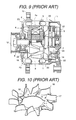
- FIG. 9 is a cross-sectional view showing a construction of an alternative current generator for vehicle according to the prior art.
- a rotor 1 is constituted by a bobbin 3 to which a field coil 4 is wound, a yoke 5 for forming a magnetic iron core, a pair of cores 2 comprised of plural claw shape configuration portion chips (plates), a front fan 15 and a rear fan 16 which are welded and fixed to an end face of the core 2, a rotating shaft 6, and a slip ring 7.
- the pair of cores 2 sandwiches the bobbin 3 to which the field coil 4 is wound and the yoke 5 and claws 2a are arranged to mesh, and the cores 2 are inserted and fixed to a substantial center portion of the rotating shaft 6.
- a stator 8 is arranged and to surround the stator 8 a front bracket 10 and a rear bracket 11 are installed.
- a pulley 12 is installed and a rotational force of an engine not shown in figure is transmitted to the pulley 12 through a belt not shown in figure and the rotor 1 is rotated and driven.
- the front fan 15 and the rear fan 16 which are installed to the core 2 rotate together and an inner portion of the generator is ventilation-cooled.
- the front side bracket 10 has plural intake holes 22 and the plural exhaust holes 23 and also the rear side bracket 11 has plural intake holes 22 and the plural exhaust holes 23, respectively, and in the rotation of the rotor 1 an interior portion of the alternative current generator is ventilation-cooled using the front fan 15 and the rear fan 16.
- Fig. 10 is a perspective view showing a fan which is employed in the alternative current generator for vehicle according to the prior art.
- a conventional fan 16 is transformed from one sheet thin plate using a press working, and the structure of the fan 16 is that plural curved face (or a flat face) blades 17 are provided projectingly in an axial direction according to the transforming by a ring shape supporting plate 18 and by bending a part of the ring shape supporting plate 18.
- a sheet number of the blades 17 and a height of the blades 17 have a relative relationship, therefore a freedom degree in a fan design receives a restriction.
- the noise increase has restrained by an alternation of the sheet number of the blades of the cooling fan, an alternation of a curvature radius of the blades, an employment of back ward blades, and an employment of an irregular pitch arrangement of the blades.
- the silence noise performance at the vehicle side an engine except for the alternative current generator, auxiliary machineries, etc.
- a correspondence to the low noise performance by the alternation of the shape configuration by a thin plate press transforming fan according to the prior art reaches to the limitation.
- An object of the present invention is to obtain an alternative current generator for a vehicle wherein a fan structure in which a freedom degree on a shape configuration design can be made high, an installation strength similar to that of the thin plate transforming fan according to the prior art can be obtained, further an alternation in a fan installation process can not be generated.
- an alternative current generator for a vehicle comprising a pair of cores having plural claw shape portion configuration plates, a rotating shaft inserted into a center portion of the core, a rotor inserted and fixed to the rotating shaft and having an excitation current supply use slip ring, a stator provided at an outer periphery of the rotor, and a front side bracket and a rear side bracket arranged to surround the rotor and the stator, the rotor is supported to rotate freely each of the brackets through a bearing member, the core is comprised of a pair of a front fan and a rear fan which are installed to both ends of said core, to end portions of the respective front side and rear side brackets plural intake holes are provided, and an outer peripheral portion of respective front side an rear side brackets plural exhaust holes are provided, and in accordance with a rotation of the rotor an inner portion of the generator is ventilation-cooled using the front and rear fans.
- the alternative current generator for the vehicle is characterized in that at least one of the front fan and the rear fan is a resin molding fan having an insert metal fitting, and a fixing of the resin molding fan to the core is carried out by joining the insert metal fitting to the core by using a joining means such as a welding.
- the blade shape configuration can be realized by the curved face, the flat face and also the three dimensional shape configuration, and further a ring shape rectifying plate can be provided in the tip end side of the blade. Further, according to the employment of the resin molding fan, the sheet number of the blades and the suitable pitch of the blades can be established freely within a realizable degree.
- the inner diameter of the ring shape supporting plate in which the blades of the cooling fan are projectingly provided is established to have substantially same diameter of the outer diameter of the rotating shaft of the rotor or the outer diameter of the slip ring which is inserted and fixed to the rotating shaft, the positioning of the axial center against the core of the cooling fan during the installation time of the cooling fan to the back face of the core can be carried out easily.
- the raised portion which is suited to the root portion of the core is provided, as a result the positioning of the cooling fan against to the rotation direction of the core can be carried out easily.
- Fig. 4 is a cross-sectional view showing an alternative current generator for vehicle according to the present invention.
- a rotor 1 is constituted by a pair of claw shape cores 2 on which plural claws 2a are provided respectively, a bobbin 3 on which a field coil 4 is wound, a yoke 5 for forming a magnetic pole iron core of the bobbin 3, a rotating shaft 6, and an excitation current supply use slip ring 7.
- the claws 2a of the core 2 are opposed to mesh and the bobbin 3 and the yoke 5 are arranged to be sandwiched, and the rotating shaft 6 is inserted under pressure and fixed to these axial centers.
- a front fan 13 and a rear fan 14 are installed integrally to the cores 2. Further, in an one end portion of the rotating shaft 6, a pulley 12 is installed and in another end portion of the rotating shaft 6, the slip ring 7 is inserted under pressure and the pulley 12 and the slip ring 7 rotate by forming integrally with the rotating shaft 6.
- a stator 8 is arranged on an outer periphery of the cores 2 to have a minute gap with the cores 2.
- a voltage regulator is mounted actually.
- a front side bracket 10 and a rear side bracket 11 support the rotating shaft 6 and are arranged to surround the rotor 1 and further sandwich the stator 8.
- the front side bracket 10 has plural intake holes 22 and the plural exhaust holes 23 and also the rear side bracket 11 has plural intake holes 22 and the plural exhaust holes 23, respectively, and in the rotation of the rotor 1 an interior portion of the alternative current generator is ventilation-cooled using the front fan 15 and the rear fan 16.
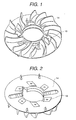
- Fig. 1 and Fig. 2 are perspective views of a blade face of the rear fan 14 according to the present invention and a back face of the rear fan 14, and Fig. 3 is a perspective view of an insert metal fitting (an insert terminal) 19 according to the present invention which is molded integrally with the rear fan 14.
- the rear fan 14 is made of a resin product in which the insert metal fitting 19 is molded integrally.
- the insert metal fitting 19 is not a mere flat plate but the insert metal fitting 19 itself is molded on an even and uneven face, and to an outer peripheral portion plural empty holes 19c or raised portions 19 are provided, as a result the shape configuration of the insert metal fitting 19 is that the combination between the resin during the insert molding time and the insert metal fitting 19 is strengthened.
- the material of the rear fan 14 is used according to a glass reinforced nylon etc. taking into the consideration of the molding performance and the strength performance and the freedom degree in the design relating to the sheet number of the blades and the height of the blades, and the arrangement of the blades, etc. can be improved.
- Fig. 5 is a detailed cross-sectional view showing an installation condition of the fan to which the alternative current generator for vehicle of the Carrying-Out Embodiment 2 according to the present invention is applied.
- the rear fan 14 is contacted to a back face of the core 2, and after positioning, in the welding portions 19 the welding is carried out and then the fan is fixed.
- a resin portion inner diameter size 1 of the resin mold rear fan 14 in which the insert metal fitting 19 is molded integrally is established to have the substantial same diameter of a resin portion inner diameter size 1 of the slip ring 7.
- Fig. 6 is a perspective view showing a before condition for installing the fan which is applied to the alternative current generator for vehicle of the Carrying-Out Embodiment 3 according to the present invention to the core
- Fig. 7 is a view showing an installation condition of the fan in the alternative current generator for vehicle of the Carrying-Out Embodiment 3 according to the present invention.
- a total four portions, namely one side two portions, of trapezoid shape configuration positioning use raised portions 20 which are suited to the back face portion shape configuration of the core 2 are provided. Since an interval 2 of the positioning use raised portions 20 is established to have a minute gap degree to a width 2 of the back face of the core 2, during the installation time of the fan 14 to the core 2 the positioning of the rear fan 14 against the rotation direction of the core 2 can be carried out easily, the working performance during the installation time can be improved.
- the shape configuration of the positioning use raised portion 20 has the trapezoid shape configuration, but the shape configuration of the positioning use raised portion is not limited to the above, as shown in Fig. 8, a convex shape configuration 21 which is suited to the shape configuration of the root portion of the core 2 can be employed.
- the insert metal fitting is formed with the integral molding resin product, the freedom degree in the design relating to the sheet number of the blades of the cooling fan, the shape configuration of the blades of the cooling fan, the arrangement pitch of the blades of the cooling fan can be improved and further it is possible to carry out the welding fixing in the alternative current generator for the vehicle.
- the inner diameter portion of the cooling fan is established to have the substantial same to the outer diameter of the shaft or the slip ring resin portion, during the installation time the positioning of the axial center of the cooling fan and the core can be carried out easily, accordingly the working performance of the alternative current generator for the vehicle can be improved.
- the raised portion suited to the back face of the core is provided, during the installation time the positioning of the rotation direction of the fan and the core is carried out easily, accordingly the working performance of the alternative current generator for the vehicle can be improved.
Landscapes
- Engineering & Computer Science (AREA)
- Mechanical Engineering (AREA)
- General Engineering & Computer Science (AREA)
- Power Engineering (AREA)
- Motor Or Generator Cooling System (AREA)
- Synchronous Machinery (AREA)
Abstract
Description
Claims (3)
- In an alternative current generator for vehicle comprising a pair of cores (2) having plural claw shape portion configuration plates, a rotating shaft (6) inserted into a center portion of said core (2), a rotor (1) inserted and fixed to said rotating shaft (6) and having an excitation current supply use slip ring (7), a stator (8) provided at an outer periphery of said rotor (1), and a front side bracket (10) and a rear side bracket (11) arranged to surround said rotor (1) and said stator (8);said rotor (1) is supported to rotate freely each of said front side and rear side brackets (10, 11) through a bearing member, said core (2) is comprised of a pair of a front fan (13) and a rear fan (14) which are installed to both ends of said core (2), to end portions of said respective front side and rear side brackets (10, 11) plural intake holes (22) are provided, and an outer peripheral portion of said respective front side and rear side brackets (10, 11) plural exhaust holes (23) are provided, and in accordance with a rotation of said rotor (1) an inner portion of said generator is ventilation-cooled using said front and rear fans (13, 14), said alternative current generator for vehicle is characterized in thatat least one of said front fan (13) and said rear fan (14) is a resin molding fan having an insert metal fitting (19); anda fixing of said resin molding fan to said core (2) is carried out by joining said insert metal fitting (19) to said core (2) by using a joining means such as a welding.
- An alternative current generator for vehicle according to claim 1, is characterized in thatsaid resin molding fan is a centrifugal fan which is comprised of a ring shape supporting plate in which plural blades are provided projectingly in an axial direction; andan inner diameter of said ring shape supporting plate is established substantially same to an outer diameter of said rotating shaft (6) of said rotor (1) or an outer diameter of a resin portion of said slip ring (7) which is inserted and fixed to said rotating shaft (6).
- An alternative current generator for vehicle according to claim 1 or claim 2, is characterized in thatsaid resin molding fan is a centrifugal fan which is comprised of a ring shape supporting plate in which plural blades are provided projectingly in an axial direction; andto a rear face (a contact face with said core (2) ) of a blade projecting face of said ring shape supporting plate, a raised portion (20) which is suited to a back face portion shape configuration of said core is provided.
Applications Claiming Priority (2)
| Application Number | Priority Date | Filing Date | Title |
|---|---|---|---|
| JP2000027215A JP3449330B2 (en) | 2000-01-31 | 2000-01-31 | AC generator for vehicles |
| JP2000027215 | 2000-01-31 |
Publications (2)
| Publication Number | Publication Date |
|---|---|
| EP1122864A2 true EP1122864A2 (en) | 2001-08-08 |
| EP1122864A3 EP1122864A3 (en) | 2003-02-12 |
Family
ID=18552813
Family Applications (1)
| Application Number | Title | Priority Date | Filing Date |
|---|---|---|---|
| EP01101620A Withdrawn EP1122864A3 (en) | 2000-01-31 | 2001-01-25 | Cooling fan for a vehicle alternator |
Country Status (3)
| Country | Link |
|---|---|
| US (1) | US6586853B2 (en) |
| EP (1) | EP1122864A3 (en) |
| JP (1) | JP3449330B2 (en) |
Cited By (5)
| Publication number | Priority date | Publication date | Assignee | Title |
|---|---|---|---|---|
| WO2005091465A3 (en) * | 2004-02-27 | 2005-12-08 | Valeo Equip Electr Moteur | Rotor assembly, in which at least one inter-claw space is sealed by the fan |
| EP1398864A3 (en) * | 2002-09-10 | 2006-07-12 | Matsushita Electric Works, Ltd. | Electric power tool |
| US7168922B2 (en) | 2004-04-26 | 2007-01-30 | Borgwarner Inc. | Plastic fans having improved fan ring weld line strength |
| CN104396126A (en) * | 2012-06-28 | 2015-03-04 | 三菱电机株式会社 | Rotating electrical machine for vehicle |
| EP3815218A1 (en) * | 2018-06-27 | 2021-05-05 | Valeo Equipements Electriques Moteur | Pole wheel for a rotor for a rotating electrical machine |
Families Citing this family (29)
| Publication number | Priority date | Publication date | Assignee | Title |
|---|---|---|---|---|
| US6794773B2 (en) * | 2001-01-23 | 2004-09-21 | General Electric Company | Winding restraint on wound rotor generators or motors and method for forming the same |
| DE10110128B4 (en) * | 2001-03-02 | 2015-07-02 | Robert Bosch Gmbh | Electric machine |
| FR2824201B1 (en) * | 2001-04-27 | 2003-08-01 | Valeo Equip Electr Moteur | VENTILATION DEVICE FOR ROTATING ELECTRIC MACHINE |
| US6680552B2 (en) | 2002-01-24 | 2004-01-20 | Visteon Global Technologies, Inc. | Flow path for a liquid cooled alternator |
| US6674188B2 (en) | 2002-03-01 | 2004-01-06 | Visteon Global Technologies, Inc. | Liquid cooled alternator |
| US6707181B1 (en) | 2002-11-15 | 2004-03-16 | Visteon Global Technologies, Inc. | Alternator fan |
| FR2857171B1 (en) * | 2003-07-04 | 2005-09-09 | Valeo Equip Electr Moteur | FAN FOR ALTERNATOR-STARTER |
| GB0329607D0 (en) * | 2003-12-20 | 2004-01-28 | Johnson Electric Sa | Electric motor |
| FR2869477B1 (en) * | 2004-03-26 | 2007-07-27 | Valeo Equip Electr Moteur | ROTATING ELECTRICAL MACHINE, IN PARTICULAR ALTERNATOR FOR A MOTOR VEHICLE, WHOSE AIR INPUTS / OUTPUTS INCLUDE INCLINED FINS WITH RESPECT TO THE BLADES OF THE FANS |
| JP4123197B2 (en) * | 2004-06-28 | 2008-07-23 | 株式会社デンソー | AC generator for vehicles |
| JP4265571B2 (en) * | 2005-06-01 | 2009-05-20 | 株式会社デンソー | Vehicle alternator |
| JP4857631B2 (en) * | 2005-07-15 | 2012-01-18 | 日本電産株式会社 | Fan motor |
| US7129604B1 (en) * | 2006-01-04 | 2006-10-31 | Wen-Chang Wang | Air cooled type generator that is mounted in easier and quicker manner |
| EP2158664A4 (en) * | 2007-06-12 | 2014-02-26 | Carrier Corp | Two-stage cooling fan for an electric generator |
| JP5079006B2 (en) * | 2007-08-09 | 2012-11-21 | 三菱電機株式会社 | Brushless AC generator for vehicles |
| CN101645633B (en) * | 2008-08-04 | 2012-09-05 | 德昌电机(深圳)有限公司 | Motor with ventilating structure |
| KR101214190B1 (en) | 2008-11-04 | 2013-01-09 | 한국델파이주식회사 | Cooling fan for connecting field coil and lead wire of an alternator for a vehicle |
| JP2011250636A (en) * | 2010-05-28 | 2011-12-08 | Hitachi Automotive Systems Ltd | Vehicle rotating electric machine |
| DE102010029836A1 (en) | 2010-06-09 | 2011-12-15 | Robert Bosch Gmbh | Electric machine with a fan |
| EP2602917B1 (en) * | 2010-08-04 | 2020-07-22 | Mitsubishi Electric Corporation | Dynamo-electric machine |
| CN103282672A (en) * | 2011-01-05 | 2013-09-04 | 博格华纳公司 | Impeller design for fluid pump assembly and method of making |
| KR101470171B1 (en) * | 2013-06-20 | 2014-12-09 | 현대자동차주식회사 | Mortor generator for vehicle |
| CN104242553B (en) * | 2014-09-25 | 2017-02-15 | 苏州圆能动力科技有限公司 | Fan assembly structure for generator |
| CA2961893C (en) * | 2016-03-29 | 2022-08-30 | Dixie Electric Ltd. | External fan and drive end housing for an air cooled alternator |
| CN105958683B (en) * | 2016-06-17 | 2018-12-25 | 珠海格力电器股份有限公司 | rotor, motor and compressor |
| CN109565232B (en) * | 2016-08-05 | 2021-02-05 | 日本电产株式会社 | motor |
| WO2018173104A1 (en) * | 2017-03-21 | 2018-09-27 | 三菱電機株式会社 | Electric motor and air blowing device |
| KR102641937B1 (en) * | 2022-03-17 | 2024-02-27 | 엘지전자 주식회사 | Motor for laundry apparatus |
| CN120979044B (en) * | 2025-10-17 | 2026-01-27 | 江苏智马科技有限公司 | A large motor with low noise and high stability |
Family Cites Families (19)
| Publication number | Priority date | Publication date | Assignee | Title |
|---|---|---|---|---|
| US3787014A (en) * | 1973-04-30 | 1974-01-22 | R Story | Replacement motor mounting |
| US4184804A (en) * | 1975-10-10 | 1980-01-22 | Nippon Soken, Inc. | Rotary electric machine having a cooling fan |
| JPS6012859B2 (en) * | 1976-02-20 | 1985-04-03 | 株式会社日本自動車部品総合研究所 | Rotating electrical machine with cooling fan |
| US4186320A (en) * | 1977-10-21 | 1980-01-29 | Electromatic Drive Corporation | Hysteresis brake assembly |
| US4799309A (en) * | 1987-12-24 | 1989-01-24 | Ford Motor Company | Method of making a rectifier and control module for an alternator |
| US4879483A (en) | 1988-06-03 | 1989-11-07 | Century Electric, Inc. | Molded multi-part generator fan |
| US4961016A (en) * | 1989-08-09 | 1990-10-02 | General Motors Corporation | Dual-face cooling fan for a dynamoelectric machine |
| EP0454039B1 (en) * | 1990-04-24 | 1996-10-23 | Nippondenso Co., Ltd. | Alternating current generator having a plurality of independent three-phase windings |
| JP2953050B2 (en) | 1990-11-29 | 1999-09-27 | 株式会社デンソー | AC generator for vehicles |
| FR2673338B1 (en) * | 1991-02-22 | 1995-05-05 | Valeo Equip Electr Moteur | FAN FOR ROTATING ELECTRIC MACHINES, PARTICULARLY FOR MOTOR VEHICLE ALTERNATORS. |
| JPH0530707A (en) | 1991-07-19 | 1993-02-05 | Mitsubishi Electric Corp | Ac generator for automobile |
| JP2828587B2 (en) | 1993-12-28 | 1998-11-25 | 三菱電機株式会社 | Cooling fan for vehicle alternator |
| JP2828586B2 (en) * | 1993-12-28 | 1998-11-25 | 三菱電機株式会社 | Rotating fan |
| US5962942A (en) * | 1996-05-31 | 1999-10-05 | The Turbo Genset Company Limited | Rotary electrical machines |
| US5793143A (en) * | 1997-08-05 | 1998-08-11 | Ford Motor Company | Rotor for an electrical machine |
| US5998891A (en) * | 1997-08-19 | 1999-12-07 | Unit Parts Company | Alternator with an improved battery terminal assembly |
| US6166462A (en) * | 1998-05-04 | 2000-12-26 | Ametek, Inc. | Bypass motor/fan assembly having separate working air passages |
| JP3435075B2 (en) * | 1998-09-07 | 2003-08-11 | 三菱電機株式会社 | AC generator for vehicles |
| US6369471B1 (en) * | 2000-11-28 | 2002-04-09 | Delphi Technologies, Inc. | Slip ring end (SRE) fan having coil lead retention feature |
-
2000
- 2000-01-31 JP JP2000027215A patent/JP3449330B2/en not_active Expired - Fee Related
-
2001
- 2001-01-25 EP EP01101620A patent/EP1122864A3/en not_active Withdrawn
- 2001-01-31 US US09/774,092 patent/US6586853B2/en not_active Expired - Lifetime
Cited By (6)
| Publication number | Priority date | Publication date | Assignee | Title |
|---|---|---|---|---|
| EP1398864A3 (en) * | 2002-09-10 | 2006-07-12 | Matsushita Electric Works, Ltd. | Electric power tool |
| WO2005091465A3 (en) * | 2004-02-27 | 2005-12-08 | Valeo Equip Electr Moteur | Rotor assembly, in which at least one inter-claw space is sealed by the fan |
| US8803396B2 (en) | 2004-02-27 | 2014-08-12 | Valeo Equipements Electriques Moteur | Rotor assembly, in which at least one inter-claw space is sealed by the fan |
| US7168922B2 (en) | 2004-04-26 | 2007-01-30 | Borgwarner Inc. | Plastic fans having improved fan ring weld line strength |
| CN104396126A (en) * | 2012-06-28 | 2015-03-04 | 三菱电机株式会社 | Rotating electrical machine for vehicle |
| EP3815218A1 (en) * | 2018-06-27 | 2021-05-05 | Valeo Equipements Electriques Moteur | Pole wheel for a rotor for a rotating electrical machine |
Also Published As
| Publication number | Publication date |
|---|---|
| EP1122864A3 (en) | 2003-02-12 |
| US6586853B2 (en) | 2003-07-01 |
| US20010010434A1 (en) | 2001-08-02 |
| JP2001218433A (en) | 2001-08-10 |
| JP3449330B2 (en) | 2003-09-22 |
Similar Documents
| Publication | Publication Date | Title |
|---|---|---|
| US6586853B2 (en) | Rotary cooling fan for an AC generator | |
| EP1018795B1 (en) | Structure of rotor for outer rotor type brushless motor | |
| US4203710A (en) | Unified pump and generator arrangement | |
| JP3279258B2 (en) | AC generator for vehicles | |
| US6172433B1 (en) | Alternating current generator with improved fans system | |
| KR100382578B1 (en) | Rotor for an alternator | |
| JP2828587B2 (en) | Cooling fan for vehicle alternator | |
| EP0418027A1 (en) | A cooling fan for rotating electrical machinery | |
| JP3458506B2 (en) | AC generator for vehicles | |
| JP2924689B2 (en) | Generator | |
| WO1999021265A1 (en) | Ac generator for vehicle | |
| US4360749A (en) | Automotive alternator construction | |
| JP2001333558A (en) | Method of manufacturing vehicle alternator and cooling fan | |
| JP3294497B2 (en) | Alternator | |
| EP1443627B1 (en) | Generator with air deflector | |
| JP3876912B2 (en) | AC generator for vehicles | |
| JP2003525006A (en) | Electric machine | |
| JP3644126B2 (en) | AC generator | |
| JPH0542218B2 (en) | ||
| JPH07107704A (en) | Vehicle alternator | |
| JPH09201009A (en) | AC generator | |
| US7425784B2 (en) | Alternator having driving pulley with end flanges | |
| JP2797823B2 (en) | AC generator for vehicles | |
| CN224177988U (en) | External rotor of permanent magnet variable frequency generator | |
| CN222928170U (en) | Outer rotor motor |
Legal Events
| Date | Code | Title | Description |
|---|---|---|---|
| PUAI | Public reference made under article 153(3) epc to a published international application that has entered the european phase |
Free format text: ORIGINAL CODE: 0009012 |
|
| AK | Designated contracting states |
Kind code of ref document: A2 Designated state(s): AT BE CH CY DE DK ES FI FR GB GR IE IT LI LU MC NL PT SE TR |
|
| AX | Request for extension of the european patent |
Free format text: AL;LT;LV;MK;RO;SI |
|
| PUAL | Search report despatched |
Free format text: ORIGINAL CODE: 0009013 |
|
| AK | Designated contracting states |
Designated state(s): AT BE CH CY DE DK ES FI FR GB GR IE IT LI LU MC NL PT SE TR |
|
| AX | Request for extension of the european patent |
Extension state: AL LT LV MK RO SI |
|
| 17P | Request for examination filed |
Effective date: 20030328 |
|
| AKX | Designation fees paid |
Designated state(s): DE FR IT |
|
| 17Q | First examination report despatched |
Effective date: 20070416 |
|
| STAA | Information on the status of an ep patent application or granted ep patent |
Free format text: STATUS: THE APPLICATION IS DEEMED TO BE WITHDRAWN |
|
| 18D | Application deemed to be withdrawn |
Effective date: 20090801 |