EP1122581A2 - Image blur correcting system - Google Patents
Image blur correcting system Download PDFInfo
- Publication number
- EP1122581A2 EP1122581A2 EP00128542A EP00128542A EP1122581A2 EP 1122581 A2 EP1122581 A2 EP 1122581A2 EP 00128542 A EP00128542 A EP 00128542A EP 00128542 A EP00128542 A EP 00128542A EP 1122581 A2 EP1122581 A2 EP 1122581A2
- Authority
- EP
- European Patent Office
- Prior art keywords
- image blur
- blur correcting
- drive signal
- correcting means
- driving
- Prior art date
- Legal status (The legal status is an assumption and is not a legal conclusion. Google has not performed a legal analysis and makes no representation as to the accuracy of the status listed.)
- Granted
Links
Images















Classifications
-
- G—PHYSICS
- G02—OPTICS
- G02B—OPTICAL ELEMENTS, SYSTEMS OR APPARATUS
- G02B27/00—Optical systems or apparatus not provided for by any of the groups G02B1/00 - G02B26/00, G02B30/00
- G02B27/64—Imaging systems using optical elements for stabilisation of the lateral and angular position of the image
- G02B27/646—Imaging systems using optical elements for stabilisation of the lateral and angular position of the image compensating for small deviations, e.g. due to vibration or shake
-
- G—PHYSICS
- G03—PHOTOGRAPHY; CINEMATOGRAPHY; ANALOGOUS TECHNIQUES USING WAVES OTHER THAN OPTICAL WAVES; ELECTROGRAPHY; HOLOGRAPHY
- G03B—APPARATUS OR ARRANGEMENTS FOR TAKING PHOTOGRAPHS OR FOR PROJECTING OR VIEWING THEM; APPARATUS OR ARRANGEMENTS EMPLOYING ANALOGOUS TECHNIQUES USING WAVES OTHER THAN OPTICAL WAVES; ACCESSORIES THEREFOR
- G03B2205/00—Adjustment of optical system relative to image or object surface other than for focusing
- G03B2205/0007—Movement of one or more optical elements for control of motion blur
-
- G—PHYSICS
- G03—PHOTOGRAPHY; CINEMATOGRAPHY; ANALOGOUS TECHNIQUES USING WAVES OTHER THAN OPTICAL WAVES; ELECTROGRAPHY; HOLOGRAPHY
- G03B—APPARATUS OR ARRANGEMENTS FOR TAKING PHOTOGRAPHS OR FOR PROJECTING OR VIEWING THEM; APPARATUS OR ARRANGEMENTS EMPLOYING ANALOGOUS TECHNIQUES USING WAVES OTHER THAN OPTICAL WAVES; ACCESSORIES THEREFOR
- G03B2217/00—Details of cameras or camera bodies; Accessories therefor
- G03B2217/005—Blur detection
Definitions
- the present invention relates to an improvement in an image blur correcting system, a camera system, a camera and an interchangeable lens which are structured by combination of a photographing device having a blur detecting means with an optical device having an image blur correcting means.
- the blur prevention sensitivity needs to be adjusted in order to appropriately conduct the image blur correcting operation by the above blur detecting means, the image blur correcting means and so on.
- the blur prevention sensitivity is directed to the ratio of the driven amount of the blur correction lens to the inclined amount of the device. That is, the blur prevention sensitivity is data pertaining to how many millimeters the blur correction lens needs to be shifted in order to correct the image blur caused by the hand fluctuated angular displacement of, for example, 1°.
- the blur prevention sensitivity changes in accordance with the zooming and focusing states.
- arithmetic operation for adjustment of the blur prevention sensitivity is conducted by a microcomputer equipped within a lens at an interchangeable lens side.
- the blur prevention sensitivity is determined on the basis of zoom information and focus information which have been detected by a zoom encoder and a focus encoder, respectively, by the microcomputer within the lens, and arithmetic operation that multiplies the blur prevention sensitivity by the blur signal transmitted from the camera side is conducted to obtain the driving displacement of the blur correction lens.
- the coordinate position drive signal of the blur correction lens requires an accuracy of from 11 to 12 bits as the blur prevention accuracy assuming that the maximum size of a screen is 36 mm and the resolution is 100/mm.
- the traffic becomes "drive command (8 bits)” + “driven amount superordination (8 bits)” + “driven amount subordination (8 bits)”.
- the traffic becomes 6 bytes (6 ⁇ 8 bits). Then, in order to correct the hand fluctuation, it is necessary to conduct the transmission of 6 bytes for each of about 1 mS. For that reason, the traffic between the camera and the interchangeable lens becomes large.
- the present invention has been made to solve the above problems with the conventional system, and therefore an object of the present invention is to provide an image blur correcting system including a photographing device and an optical device which is capable of reducing an arithmetic operation load pertaining to an image blur correction at the optical device side.
- an image blur correcting system formed of the combination of a photographing device having blur detecting means and an optical device having image blur correcting means, wherein
- the photographing device side having the blur detecting means conducts the arithmetic operation on the basis of the relation between the detection output value of the blur detecting means and the driven amount of the image blur correcting means which corresponds to the detection output value, and the signal obtained by the arithmetic operation is transmitted to the optical device side having the image blur correcting means.
- a camera system formed of the combination of a camera having blur detecting means and an interchangeable lens having image blur correcting means, wherein
- the arithmetic operation is conducted on the basis of the relation between the detection output value of the blur detecting means and the driven amount of the image blur correcting means which corresponds to the detection output value at the camera side having the blur detecting means, and the signal obtained by the arithmetic operation is transmitted to the interchangeable lens side having the image blur correcting means.
- a camera having blur detecting means used in combination with an interchangeable lens having image blur correcting means comprising:
- the arithmetic operation is conducted at the camera side on the basis of the relation between the detection output value of the blur detecting means and the driven amount of the image blur correcting means which corresponds to the detection output value, and the signal obtained by the arithmetic operation is transmitted to the interchangeable lens side having the image blur correcting means.
- an interchangeable lens having image blur correcting means used in combination with a camera having blur detecting means comprising:
- the arithmetic operation is conducted at the camera side on the basis of the relation between the detection output value of the blur detecting means and the driven amount of the image blur correcting means which corresponds to the detection output value, and the signal obtained by the arithmetic operation is transmitted to control the driving of the image blur correcting means in accordance with the drive signal.
- another object of the present invention is to provide an image blur correcting system, a camera system, a camera and an interchangeable lens which are capable of reducing the communication load related to the drive depending on a drive target position of the image blur correcting means.
- an image blur correcting system formed of the combination of a photographing device having blur detecting means with an optical device having image blur correcting means, wherein
- an image blur correcting system formed of the combination of a photographing device having blur detecting means with an optical device having image blur correcting means, wherein
- a camera system formed of the combination of a camera having blur detecting means with an interchangeable lens having image blur correcting means, wherein
- a camera having blur detecting means which constitutes a camera system in combination with an interchangeable lens having image blur correcting means, the camera comprising: transmitting means for transmitting to the interchangeable lens a given-position drive signal for driving the image blur correcting means to a given position or a coordinate position drive signal of the image blur correcting means which is calculated on the basis of an output of the blur detecting means.
- an interchangeable lens having image blur correcting means which constitutes a camera system in combination with the camera of the above aspect of the invention, the interchangeable lens comprising: drive control means for controlling the driving of the image blur correcting means in accordance with the given-position drive signal transmitted from the camera or the coordinate position drive signal.
- a camera system formed of the combination of a camera having blur detecting means with an interchangeable lens having image blur correcting means, wherein
- a camera having a blur detecting means which constitutes a camera system in combination with an interchangeable lens having image blur correcting means, the camera comprising: transmitting means for transmitting to the interchangeable lens a given-angle-of-view drive signal for driving the image blur correcting means to a given angle of view or a coordinate position drive signal of the image blur correcting means which is calculated on the basis of an output of the blur detecting means.
- an interchangeable lens which constitutes a camera system in combination with the camera as described above, the interchangeable lens comprising: drive control means for controlling the driving of the image blur correcting means in accordance with the given-angle-of-view drive signal transmitted from the camera or the coordinate position drive signal.
- Still another object of the present invention is to provide an image blur correcting system, a camera system and an interchangeable lens which are capable of suppressing a power consumption or reducing a power consumption by stopping the useless driving of the image blur correcting means in the case where a signal related to the driving of the image blur correcting means does not occur for a predetermined period of time.
- an image blur correcting system formed of the combination of a photographing device having blur detecting means with an optical device having image blur correcting means, wherein
- an image blur correcting system formed of the combination of a photographing device having blur detecting means with an optical device having image blur correcting means, wherein
- a camera system formed of the combination of a camera having blur detecting means with an interchangeable lens having image blur correcting means, wherein
- a camera system formed of the combination of a camera having blur detecting means with an interchangeable lens having image blur correcting means, wherein
- an interchangeable lens having image blur correcting means which constitutes a camera system in combination with a camera having blur detecting means
- the interchangeable lens comprising: drive control means for controlling the driving of the image blur correcting means on the basis of the signal related to the driving of the image blur correcting means upon receiving the signal from the camera and for stopping the driving of the image blur correcting means when not receiving the signal related to the driving of the image blur correcting means for a predetermined period of time.
- an interchangeable lens having image blur correcting means which constitutes a camera system in combination with a camera having blur detecting means
- the interchangeable lens comprising: drive control means for controlling the driving of the image blur correcting means on the basis of the signal related to the driving of the image blur correcting means upon receiving the signal, and for driving the image blur correcting means to a predetermined position and stopping the driving of the image blur correcting means when not receiving the signal related to the driving of the image blur correcting means for a predetermined period of time.
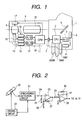
- Fig. 1 is a structural diagram showing a camera system made up of a camera (camera main body) and an interchangeable lens in accordance with the respective embodiments of the present invention.
- a CPU 2 that controls the camera side is equipped within the camera 1, and blur sensors (or fluctuation sensor) 4 and 5 that output the blur or fluctuation in yaw and pitch directions of the camera are disposed as shown in the figure.
- Both of the outputs of the blur sensors 4 and 5 are converted into digital data by an A/D convertor 3 and then taken in as data within the CPU 2.
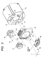
- the blur sensors 4 and 5 are made up of a vibration gyro as an angular velocity sensor, an integrating circuit and so on as shown in Fig. 2.
- the vibration gyro 20 is resonantly driven by a driving circuit 22, and its output is so converted as to be a given angular velocity output by a synchronous detection circuit 21 or the like.
- the output from the synchronous detection circuit 21 normally contains unnecessary d.c. offset, and the d.c. component is removed by a high-pass filter made up of a capacitor 24 and a resistor 25, and only the remaining blur signal is amplified by an amplifier made up of an operational amplifier 23 and resistors 26 and 27.
- an output of the amplifier is integrated by an integrating circuit made up of an operational amplifier 28, resistors 29, 30 and a capacitor 31 and then converted into an output which is proportional to a blur displacement.
- the integrated output is outputted to the A/D convertor 3 as described above.
- the sensor output taken within the CPU 2 becomes a blur correction lens driven amount which has been arithmetically operated on the basis of information from the interchangeable lens 8. Then, the data of the blur correction lens driven amount is transferred to the CPU 11 within the interchangeable lens 8 by the CPU 2 through a normal serial bus line 7 that conducts an interchange of information between the camera 1 and the interchangeable lens 8.
- outputs of position detecting sensors 15 and 16 that detect the absolute position of a blur correcting system 9 per se are converted into digital data by an A/D convertor 18 and then taken in the CPU 11.
- the data of the blur correction lens driven amount from the camera 1 is compared with the position of the blur correcting system 9, and the comparison result is transferred to a D/A convertor 12.
- the blur correcting system 9 is driven through driver circuits 13 and 14 on the basis of the output result from the D/A convertor 12, to thereby correct an image blur.
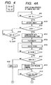
- FIG. 3 A specific structural example of the blur correcting system 9 is shown in Fig. 3.
- Fig. 3 shows the structure of a so-called shift optical system that corrects the angular blur of a camera by shifting the blur correction lens in parallel in x- and y- directions perpendicular to an optical axis.
- reference numerals 50 and 51 respectively denote yoke portions as magnetic circuit units that become actual driving sources in x- and y-axial directions, respectively
- reference numeral 52 and 53 are coil portions corresponding to the respective yokes. Therefore, when a current is supplied to the coil portions 52 and 53 by the above-mentioned driver circuits 13 and 14, the correction lens 54 which is a part of the photographing lens is eccentrically driven in the x- and y- directions.
- Reference numeral 55 denotes a support arm and support frame for fixing the blur correction lens 54.
- the movement of the blur correction lens 54 is detected in a non-contact manner by the combination of IREDs 56 and 57 that move integrally with the blur correction lens 54 with PSDs 62 and 63 fitted onto a tube portion 60 for retaining the entire shift lens.
- reference numeral 58 denotes a mechanically locking mechanism for mechanically retaining the blur correction lens 54 to a position of substantially the center of the optical axis when the energization of the shift system stops
- 59 is a charge pin
- 61 is a support sphere as a door stop for regulating the falling direction of the shift system, respectively.
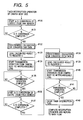
- Figs. 4A and 4B show the main process of the CPU 2 of the camera 1 which is related to the blur prevention (image blur correction) operation.
- a switch SW1 that instructs the start of the release operation of the camera 1 is on or not If the switch SW1 is on, in steps #100 and 101, judgement of whether a supply voltage is sufficient for the insurance of the operation of the entire camera or not is executed by a battery checking circuit not shown.
- the control is advanced to a step #102 where waiting is made until the switch SW1 turns off, and when the switch SW1 turns on, the operation returns to a start position again.
- the control is then advanced to a step #103 where the CPU 2 communicates with the CPU 11 within the interchangeable lens 8, to thereby obtain data used for photometric operation such as a photometry, a range finding, or a release iris value, data for adjusting the focal point such as a focal point adjustment sensitivity, and data corresponding to the blur prevention sensitivity.
- the blur prevention sensitivity is directed to a ratio of the driven amount of the blur correction lens to the inclined amount of the device as described above, which changes in accordance with a state of zoom and focus.
- the blur prevention sensitivity is used for arithmetic operation executed in a step #151 shown in Fig.
- zoom information is employed as data corresponding to the blur prevention sensitivity.
- a manner of transmitting and receiving the information is that when a given data request signal is transmitted toward the interchangeable lens 8 from the camera 1, the zoom information is transmitted to the camera 1 side as the data corresponding to the blur prevention sensitivity in response to the given data request signal at the interchangeable lens 8 side.
- step #104 normal photometric operation is conducted, and in a subsequent step #105, an actual focus control is executed by driving the focus lens through communication with an optical sensor not shown and the CPU 11.
- the focus control continues until in-focus can be detected in a step #106, and if in-focus can be detected, the control is advanced to a step #107 where it is judged whether a switch ISSW for starting the blur prevention is on or not. If the switch ISSW is off, the control is advanced to a step #108 assuming that the blur prevention operation is not necessary, and the flag ISONL within the CPU 11 is set to 0 and the control is immediately advanced to a step #116.
- step #107 if it is judged in the above step #107 that the switch ISSW is on, the control is advanced to a step #109 assuming that the blur prevention photographing operation is selected, and the lock release command is transferred to the CPU 11 of the interchangeable lens 8 side from the CPU 2 of the camera 1 side through the serial bus line 7.
- FIG. 7A and 7B An appearance of the above command communication is shown in the timing chart of Figs. 7A and 7B, and in Figs. 7A and 7B, reference SCK is a synchronous clock for serial communication, SD0 is serial data that is transferred to the interchangeable lens 8 side from the camera 1, and SD1 is serial data transmitted from the camera 1 side from the interchangeable lens 8 side at the same time.
- reference SCK is a synchronous clock for serial communication
- SD0 is serial data that is transferred to the interchangeable lens 8 side from the camera 1
- SD1 serial data transmitted from the camera 1 side from the interchangeable lens 8 side at the same time.
- a command of the mechanical lock release of at least 1 byte or more is transmitted to the interchangeable lens 8 from the camera 1
- a BUSY signal indicating that the data has been received is detected from the SD1
- the CPU 2 judges in the step #110 that the mechanical lock release operation is completed (in fact, the mechanical lock release operation is temporally slightly delayed, but it is assumed that the release is completed upon the completion of the command reception in a sequential manner).
- the control is advanced to a subsequent step #111 where a timer for conducting interruption for each of the given periods T is reset to newly start the counting operation.
- a flag ISONL within the CPU 2 indicative of the blur preventing state is set to 1, and in a subsequent step #113, the timer interruption operation is permitted.
- arithmetic operation registers UY and UP which will be described later are set to OH, respectively, and thereafter the control is advanced to a step #116 where it is judged whether the switch SW2 equipped in the camera 1 accompanied by the actual shutter release operation is on or not. If on, the control is advanced to a step #117 assuming that the operator starts the release operation, and the up operation of the mirror 6 within the camera 1 shown in Fig.1 is conducted to execute the shutter release operation.
- step #116 if it is detected in the above step #116 that the switch SW2 has not been turned on yet, the control is advanced to a step #118 assuming that the operator is still conducting framing operation (determining the photographing composition), and in this step, it is judged whether the switch SW1 is still on or not. If on, the control is again returned to the step #116, and the above operation is repeated. Also, if it is detected in the above step #118 that the switch SW1 turns off, the CPU 2 judges that the operator per se has completed the photographing of the camera, and the control is advanced to a step #119 where the contents of the above-described flag ISONL are judged.
- the control is immediately returned to the step #99 assuming that the blur preventing operation is not executed.
- the control is advanced to a step #120 assuming that the blur preventing operation has been executed, and in this step, the lock setting command is transmitted.
- the lock setting command is transmitted to the CPU 11 from the CPU 2 as in the above-described lock release command (it is needless to say that the data contents are different) as shown in the timing chart of Figs. 7A and 7B.
- step #121 it is judged whether the above lock setting has been completed or not, and if the above lock setting has been completed, the control is advanced to a step #122 where the above-mentioned timer interruption operation is inhibited to complete those sequential operation.
- a step #130 the operation of converting an output from the blur sensor 5 in the yaw direction shown in Fig. 1 into digital data by the A/D convertor 3 starts. Then, in a subsequent step #131, if it is detected that the above conversion operation has been completed, the control is advanced to a step #132, and a given arithmetic operation is conducted on the conversion result.
- the data converting operation will be described with reference to the sub-routine "data conversion" shown in Fig. 6.
- step #150 the contents of the ADDATA resistor in which the A/D conversion result is stored are transferred to the general-purpose arithmetic operation register A within the CPU 2, and in a subsequent step #151, data corresponding to the blur prevention sensitivity indicative of a relation between "blur sensor output” and “correction lens driven amount” (or data corresponding to the blur prevention sensitivity indicative of a relation between "image moving amount on an image face” and “correction lens driven amount" which is transmitted from the CPU 11 within the interchangeable lens 8, that is, in this embodiment, data corresponding to the blur prevention sensitivity which reflects the zoom state which has been already set is received, and then transferred to a general-purpose arithmetic operation register B within the CPU 2.
- a subsequent step #152 the CPU 2 multiplies two general-purpose arithmetic operation registers and sets its result at a register C.
- the data corresponding to the blur prevention sensitivity which is transferred to the general-purpose arithmetic operation register B is obtained through the communication with the interchangeable lens 8 in the step #103 shown in Figs. 4A and 4B. Since the data is updated at given time intervals as will be described later, the arithmetic operation using the latest blur prevention sensitivity can be conducted at the respective time points of the above arithmetic operation. Thereafter, the control is returned to the step #133 of Fig. 5.
- step #133 of Fig. 5 the contents of the above arithmetic operation result are transferred to the transmission data register C, and in a subsequent step #134, the operation of actually transmitting the data from the camera 1 to the interchangeable lens 8 starts.
- a command indicative of the output of the blur sensor is first transmitted (of course this command includes flags for discrimination of the yaw and pitch and the like), and the contents of the register C corresponding to the output of the blur sensor are transferred as the serial data of at least 1 byte or more.
- the interchangeable lens 8 side Upon receiving the signal, transmits the data corresponding to the blur prevention sensitivity to the camera 1 side at that time as will be described later (a step #186 in Figs. 9A and 9B).
- step #135 If it is detected in a step #135 that the data transfer of the blur correction lens driven amount has been completed, the A/D converting operation of the sensor output in the pitch direction then starts in the step #136. Since the steps #136 to #141 which is the data transmitting process of the blur correction lens driven amount in the pitch direction are entirely identical with the process of the sensor output in the yaw direction (steps #130 to #135), their description will be omitted. Finally, in the step #142, the timer interruption flag is set to 0, the interruption operation is completed, and the control is returned to the main process shown in Figs. 4A and 4B.
- the interruption operation occurs for each of the given periods T on the process of the CPU 2, and the latest data output of the blur correction lens driven amount in the yaw and pitch directions disposed within the camera 1 is transmitted to the interchangeable lens 8 side every time the interruption is made.
- subsequent steps #160 and #161 the correction arithmetic operation internal registers CY and CP for lens control are set to OH, respectively.
- an LCK flag indicative of the lock setting control is set to 0, and similarly, in a subsequent step #163, a ULCK flag indicative of the lock release control is set to 0.
- a subsequent step #164 the above-described interruption operation of the serial interface for receiving the data transmitted from the camera 1 is permitted, and in a step #165, it is judged whether a command that accelerates the lock release is received or not in the serial interface communication interruption operation which will be described later, and if the flag ULCK is 0, the control is then advanced to a step #168 as it is, assuming the lock release command is not received.
- the control is then advanced to a step #166 as it is, assuming the lock release command has been received, and the lock release operation is immediately conducted.
- a current is supplied to the plunger 58 in the mechanical lock mechanism shown in Fig. 3 in a given direction through a mechanical lock driver not shown in accordance with a control signal from the CPU 11, to thereby release the engagement of the blur correction lens 54 which is a shift lens.
- the above-mentioned flag ULCK is set to 0.
- a subsequent step #168 it is judged whether the flag LCK indicative of the lock setting is 1 or not, and if the flag LCK is 0, the control is returned to the step #165 as it is assuming that the lock setting command has not been received.
- the flag LCK is 1
- the control is advanced to a step #169 assuming that the lock setting command has been received, and the lock setting operation is immediately conducted.
- a current is supplied to the plunger 58 in the mechanical lock mechanism in a counter direction to that in case of the lock release in accordance with the control signal from the CPU 11, to thereby forcedly stop the movement of the blur correction lens 54 by a lever.
- the flag LCK is set to 0 in the step #170, and the control is returned to the step #165 again, to thereby repeat the above-mentioned operation.
- a command as the communication contents which is transmitted from the camera 1 side is decoded, and in a subsequent step #181, it is judged whether the communication contents is a lock release command or not.
- the control is advanced to a step #182, where the flag ULCK 1 for accelerating the lock release operation within the CPU 11 is set to 1, and the control is immediately advanced to a step #200 where a flag for serial interruption is set to 0, and the interruption operation is completed. Therefore, in this case, the lock release operation is executed on the main process shown in Fig. 8 as described above.
- step #181 if it is judged in the above step #181 that the communication contents are not the lock release command, the control is advanced to a step #183 where it is judged whether the communication contents are the lock setting command or not, and if the communication contents are the lock setting command, the control is advanced to a step #184 where the flag LCK for accelerating the lock setting command within the CPU 11 is set to 1, and the control is advanced to the step #200 as in the case where the lock release command is received, and the interruption operation is completed.
- step #183 the control is advanced to a step #185 where it is judged whether the communication contents are data of the blur correction lens driven amount in the yaw direction or not, and in this step, if the received command is identical with the command for the yaw-side correction lens driven amount reception, the control is then advanced to a step #186, where the contents of the serial data in the format shown in the timing chart of Figs. 7A and 7B are set at the SY register within the CPU 11.
- data corresponding to the blur prevention sensitivity indicative of a relation between "blur sensor output” and “correction lens driven amount” (or data corresponding to the blur prevention sensitivity indicative of a relation between "image moving amount on an image face” and “correction lens driven amount”) is transmitted to the camera 1 side.
- the data corresponding to the blur prevention sensitivity is data that reflects both of the zoom lens setting state and the focus lens setting state during the data transmission.
- step #188 it is judged whether the above A/D conversion operation has been completed or not.
- the control is advanced to a step #189, and its result is transferred to the TY register within the CPU 11.
- a subsequent step #190 the feedback arithmetic operation in the yaw correction system is executed so that the contents of the SY register in which the data corresponding to the output from the position detecting sensor 15 is stored are identical with the contents of the TY register in which the data corresponding to the position output of the correction system is stored, and in a subsequent step #191, the arithmetic operation result is transferred to an OY register within the CPU 11.
- the control is immediately advanced to a step #200 where the interruption operation is completed.
- step #192 it is judged whether the communication contents are the command for the pitch-direction blur correction lens driven amount data reception or not. If the communication contents are the command for the pitch-direction blur correction lens driven amount data reception, the steps #193 to #198 are executed, and the drive control of the blur correction system 9 in the pitch direction is conducted. Since this process is entirely identical with the above-mentioned drive control in the yaw direction (steps #186 to #191), its description will be omitted.
- the control is advanced to a step #199 where a normal lens communication (for example, focus or iris control, the operation of obtaining a photometry, a range finding, and a blur prevention sensitivity, etc.) is conducted, and after that operation has been completed, in a step #200, the serial communication interruption flag is cleared, and all the serial interruption operation is terminated.
- a normal lens communication for example, focus or iris control, the operation of obtaining a photometry, a range finding, and a blur prevention sensitivity, etc.
- the camera 1 side receives the data corresponding to the blur prevention sensitivity from the interchangeable lens 8 side at any time while the blur preventing operation continues, calculates the latest blur correction lens driven amount in accordance with the data and the detection output of the blur sensor, and transmits the calculated result to the interchangeable lens 8 side alternately in the yaw and pitch directions.
- the interchangeable lens 8 side executes the control of the blur correction system 9 every time the latest blur correction lens driven amount is received. Therefore, the arithmetic operation load of the CPU 11 within the interchangeable lens 8 is reduced, and the interchangeable lens 8 can be made advantageous from the viewpoint of the costs.
- the latest blur correction lens driven amount is calculated, to thereby conduct the blur preventing operation (blur correcting operation) thus being capable of always conducting the optimum blur correction.
- step #400 of Fig. 10 data used for calculating the photometry such as an open iris value and data for adjusting a focal point such as the focal point adjustment sensitivity are obtained.
- step #104 photometry operation is conducted, and at steps #105 and #106, focus adjustment operations are conducted, respectively.
- steps #105 and #106 focus adjustment operations are conducted, respectively.
- step #401 the blur prevention sensitivity that reflects both of the zoom lens setting state and the focus lens setting state in a state where in-focus is obtained, is obtained.
- the interchangeable lens 8 side transmits the blur prevention sensitivity that reflects both of the zoom lens setting state and the focus lens setting lens in a state where in-focus is obtained as the data corresponding to the blur prevention sensitivity toward the camera 1 side in accordance with the given data request signal.
- the data corresponding to the blur prevention sensitivity after in-focus has been made is used as the calculation of the blur correction lens driven amount, thereby being capable of conducting the blur correcting operation higher in precision.
- the data corresponding to the zoom lens setting state and data corresponding to the focus lens setting state may be transmitted to the camera 1 side from the interchangeable lens 8 as different data, respectively, and those data are integrated together at the camera 1 side to form the blur prevention sensitivity.
- the data corresponding to the blur prevention sensitivity obtained by integrating both of the data corresponding to the zoom lens setting state and data corresponding to the focus lens setting state together may be formed at the interchangeable lens 8 side and then transmitted to the camera 1 in that format.
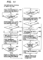
- Fig. 11 shows the timer interruption operation in which the interruption occurs for each of the given periods T at the camera side.
- step #250 the operation of converting an output from the yaw-direction blur sensor 5 shown in Fig. 1 into digital data by the A/D convertor 3 starts.
- step #251 it is judged whether the above A/D conversion operation has been completed or not. If it is judged that the above A/D conversion operation has been completed, the control is advanced to a step #252, and its result is subjected to a given arithmetic operation. Since the data conversion arithmetic operation is entirely identical with that shown in Fig. 6 which was described in the above first embodiment, its description will be omitted.
- a value of the register C within the CPU 2 in which the above arithmetic operation result is stored and a value of the internal register UY are compared with each other, and if both values are identical with each other, the control is advanced to a step #258, and the control is immediately shifted to the control of the pitch-direction sensor output detection.
- step #253 the control is advanced to a step #254, where the contents of the register C are set at the UY register for a succeeding interruption operation. Then, in a subsequent step #255, the contents of the register C are transferred to the transmission data register, and in a subsequent step #256, the contents are transmitted to the interchangeable lens 8 side in accordance with the timing chart shown in Figs. 7A and 7B.
- step #257 it is judged whether the transmission of the given number of bytes has been entirely completed or not, and if it is detected that the transmission has been completed, the control is advanced to a step #258, where the converting and transfer operation of the data of the pitch-direction blur correction lens driven amount starts. Since the operation of the steps #258 to #264 is entirely identical with the operation of the steps #250 to #257, its description will be omitted. Finally, in a step #265, the timer interruption flag is cleared, and the interruption operation is completed.
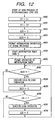
- Fig. 12 is a flowchart showing the main process of the CPU 11 at the interchangeable lens 8 side. This operation is basically entirely identical with that of Fig. 8 which is described in the above first embodiment except for a part thereof, and differences from Fig. 8 reside only in that steps #285 and #286 are newly added.
- a timer that generates the interruption for each of the given periods T is disposed at the interchangeable lens 8 side.
- the timer starts, and in a subsequent step #286, the interruption is permitted. Therefore, the main process of the CPU 11 at the interchangeable lens 8 side waits for the timer interruption where the data of the blur correction lens driven amount transmitted from the camera 1 side is received, and the blur correction system 9 is controlled for each of the given periods.
- step #300 the communication contents of a command transmitted from the camera 1 side is decoded, and if it is judged in a subsequent step #301 that the communication contents are the lock release command, the control is advanced to a step #302, where the flag ULCK for accelerating the lock release operation in the main process within the CPU 11 is set to 1, and the control is thereafter advanced to a step #310 where a flag for serial interruption is set to 0, and the interruption operation is completed.
- step #301 if it is judged in the above step #301 that the communication contents are not the lock release command, the control is advanced to a step #303 where it is judged whether the communication contents are the lock setting command or not, and if the communication contents are the lock setting command, in a subsequent step #304, the flag LCK for accelerating the lock setting command in the main process within the CPU 11 is set to 1, and in a step #310, the interruption flag of the serial communication is cleared, and the interruption operation is completed.
- step #303 the control is advanced to a step #305 where it is judged whether the communication contents are the received data of the yaw-direction sensor or not, and if the communication contents are the data of the blur correction lens driven amount in the yaw direction, the control is then advanced to a step #306, where the contents of the yaw-direction received data is set at the SY register within the CPU 11, and the interruption flag of the serial communication is cleared, and the interruption operation is completed.
- step #305 if it is judged in the above step #305 that the communication contents are not the received data of the yaw direction, the control is then advanced to a step #307, where it is judged whether the communication contents are the pitch received data or not. If it is judged that the communication contents are the received data of the pitch side sensor, the control is advanced to a step #308, and the contents of the pitch sensor received data is set at the SP register, and the interruption operation is completed through the step #310.
- step 307 if the communication contents are not also the pitch received data, it is judged that the communication contents are a normal lens communication, the control is advanced to a step #309 where the normal lens communication process is executed, and in a step #310, the interruption flag of the serial communication is cleared, and the interruption operation is completed.
- step #320 the operation of converting an output from the position detecting sensor that detects the movement of the blur correction system 9 in the yaw direction as shown in Fig. 1 into digital data by the A/D convertor 18 starts. Then, in a subsequent step #321, it is judged whether the above A/D conversion operation has been completed or not. If it is judged that the above A/D conversion operation has been completed, the control is advanced to a step #322, and its conversion result is set at the TY register within the CPU 11.
- a subsequent step #323 the feedback arithmetic operation for following the blur correction system 9 to the output of the position detecting sensor in the yaw-direction is executed by using the SY register in which a value corresponding to the data of the yaw-direction blur correction lens driven amount is stored by using the above-mentioned TY register. Then, the contents of the OY register corresponding to the arithmetic operation result are transferred to the D/A convertor 12 as DADATA in a subsequent step #324, and the blur correction system 9 is driven through the driving circuit 13 on the basis of the above result. The same is applied to the pitch direction (steps #327 to #330).
- the image blur correcting system formed of the photographing device and the optical device which is capable of reducing the arithmetic operation load related to the image blur correction at the optical device side.
- the camera system formed of a camera and an interchangeable lens which are capable of reducing the arithmetic operation load related to the image blur correction at the interchangeable lens side.
- the camera that can exhibit the image blur correction function in combination with the interchangeable lens, which are capable of reducing the arithmetic operation load related to the image blur correction on the interchangeable lens side.
- the interchangeable lens that can exhibit the image blur correcting function in combination with the camera which are capable of exhibiting the image blur correcting function without receiving the arithmetic operation load related to the image blur correction.
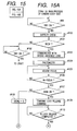
- Figs. 15A and 15B show the main process of the CPU 2 within the camera body 1 related to the blur prevention (image blur correction) operation, and since steps #99 to #115 are identical with that in Figs. 4A and 4B, their description will be omitted.
- a given-position drive signal that drives the image blur correcting means to a given position (in this example, the given position means an initial position or a center position related to both of the pitch and yaw directions is transmitted to the lens.
- the image blur correcting means drive command in the yaw direction is 40H
- the image blur correcting means drive command in the pitch direction is 41H
- the data may be set to 43H.
- those positions take different values depending on the lens individual or the lens state, that is, the optical characteristic of the interchangeable lens 8, in accordance with the position setting information of the image blur correcting means which is received in the step #103 of Figs. 4A and 4B.
- step #116 the control is advanced to a step #116 where it is judged whether the switch SW2 equipped in the camera body 1 accompanied by the actual shutter release operation is on or not, and if on, the control is advanced to a step #117 assuming that the operator starts the actual release operation, and the up-operation of the mirror 6 within the camera body 1 shown in Fig. 1 is conducted, and the shutter release operation is executed.
- step #116 if it is judged in the above step #116 that the switch SW2 is not yet on, the control is advanced to a step #118 assuming that the operator is still conducting framing operation (determining the photographing composition), and in the step, it is judged whether the switch SW1 is still on or not, if the switch SW1 is on, the control is again returned to the step #117, and the above operation is repeated. Also, if it is detected in the above step #118 that the switch SW1 becomes off, the CPU 2 judges that the operator per se has completed the photographing of the camera, and the control is advanced to the step #119, and the contents of the above-mentioned flag ISONL are judged.
- the control is immediately returned to the step #99 assuming that the blur preventing operation is not executed.
- the control is advanced to the step #121 assuming that the blur preventing operation has been executed.
- a given-position drive signal of 1 byte which drives the image blur correcting means to the initial position or the center position is transmitted to the lens.
- step #120 a lock setting command is transmitted.
- the lock setting command is transmitted from the CPU 2 to the CPU 11 as shown in the timing chart of Figs. 7A and 7B as in the above-described lock release command (it is needless to say that the data contents are different).
- step #121 it is judged whether the above lock setting has been completed or not, and if it is judged that the lock setting has been completed, the control is advanced to a step #124 where the above-mentioned timer interruption operation is inhibited, and then the sequential operation is completed.
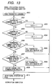
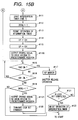
- step #1130 the operation of converting the output from the blur sensor 5 in the yaw direction as shown in Fig. 1 into the digital data by the A/D convertor 3 is started. Then, if it is judged in a subsequent step #1131 that a fact that the above converting operation has been completed, the control is advanced to a step #1132, and a given arithmetic operation is conducted on the converting result.
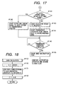
- the data converting operation will be described with reference to the sub-routine "data conversion" shown in Fig. 18.
- step #1150 the contents of an ADDATA register in which the A/D conversion result is stored is transferred to a general-purpose arithmetic operation register A in the interior of the CPU 2, and in a subsequent step #1151, data corresponding to the blur prevention sensitivity indicative of a relation between "blur sensor output” and “correction lens driven amount” which is transmitted from the CPU 11 within the interchangeable lens 8 (or data corresponding to the blur prevention sensitivity indicative of a relation between "image moving amount on an image face” and "correction lens driven amount", that is, in this embodiment, data corresponding to the blur prevention sensitivity which reflects the zoom state which has been already set is received and then transferred to a general-purpose arithmetic operation register B within the CPU 2.
- a subsequent step #1152 the CPU 2 multiplies those two general-purpose arithmetic operation registers by each other, and its result is set to the register C (corresponding to a coordinate position drive signal of 3 bytes).
- Data corresponding to the blur prevention sensitivity which is transferred to the general-purpose arithmetic operation register B is obtained through communication with the interchangeable lens 8 in the step #1103 shown in Figs. 15A and 15B, and since the data is updated at given time intervals as will be described later, arithmetic operation using the latest blur prevention sensitivity can be executed at the respective time points of the above arithmetic operation. Thereafter, the control is returned to the step #1133 shown in Fig. 16.
- step #1133 As compared with the data of the above step #1152 (the coordinate position drive signal of 3 bytes), it is judged whether a given-position drive signal of 1 byte is outputted or not.
- the given-position drive command of the image blur correcting means in the yaw direction is set as follows:
- step #1152 If it is judged that the data of the above step #1152 is equal to or close to those values, in more detail, if it is judged that the coordinate position drive signal of 3 bytes which becomes the drive target position to which the image blur correcting means is situated is identical with a predetermined given-position drive signal of 1 byte (in this example, any one of 44H to 48H) or they are substantially the same within a permissible range (within a range where the blur correction is not adversely affected), the control is advanced from the step #1133 to the step #1134 where the output of the given-position drive signal of 1 byte starts instead of the above-described coordinate position drive signal, and the control is then advanced to a step #1137.
- a predetermined given-position drive signal of 1 byte in this example, any one of 44H to 48H
- the control is advanced to a step #1135 from the step #1133 where the contents of the above-mentioned arithmetic operation result (the coordinate position drive signal of 3 bytes) are transferred to the transmission data register C, and in a subsequent step #1136, the actual transmitting operation of the data from the camera body 1 to the interchangeable lens 8 starts.
- the timing chart of Figs. In an actual data transmitting method of the blur correction lens drive amount, as shown in the timing chart of Figs.
- a command indicative of output of the blur sensor is first transmitted (it is needless to say that the command includes a flag for discrimination of the yaw, the pitch and so on), and the contents of the above register C which correspond to the next output of the blur sensor is then transferred as the serial data of at least 1 byte or more.
- the data corresponding to the blur prevention sensitivity at that time is transmitted to the camera body 1 side as will be described later (the step #1186 in Fig. 20).
- step #1137 If it is detected in a step #1137 that the transfer of the given-position drive signal or the coordinate position drive signal has been completed, the A/D converting operation with respect to the sensor output in the pitch direction starts. Since the steps #1138 to #1145 shown in Figs. 16 and 17 which are the data transmitting process with respect to the driving of the blur correction lens in the pitch direction are completely identical with the process with respect to the sensor output in the yaw direction (the steps #1130 to #1137 in Fig. 16), their description will be omitted. Finally, in a step #1146, a timer interruption flag is set to 0, the interruption operation is completed and the control is returned to the main process shown in Figs. 15A and 15B.
- the interruption occurs for each of the given periods T on the process of the CPU 2, the latest data output related to the driving of the blur correction lens in the yaw and pitch directions disposed within the camera body 1 is transmitted to the interchangeable lens 8 side every time the interruption occurs.
- a command as the communication contents transmitted from the camera body 1 side is decoded, and it is judged in a subsequent step #1181 whether the communication contents are the lock release command or not.
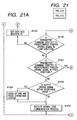
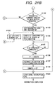
- the control is then advanced to the step #1182 where the flag ULCK for accelerating the lock release operation within the CPU 11 is set to 1, and the control is immediately advanced to a step #1206 of Figs. 21A and 21B where a flag for serial interruption is set to 0, to thereby complete the interruption operation. Therefore, in this case, the lock release operation is executed on the main process of Fig. 19 as described above.
- the control is advanced to a step #1183 where it is judged whether the communication contents are a lock setting command or not. If the communication contents are the lock setting command, the control is advanced to a step #1184 where the flag LCK for accelerating the lock setting command within the CPU 11 is set to 1, and the control is advanced to a step #1206 of Figs. 21A and 21B as in the case where the lock release command is received, to thereby complete the interruption operation.
- step #1183 if it is judged in the step #1183 that the communication contents are not the lock setting command, the control is advanced to a step #1185 where it is judged whether the communication contents are the coordinate position drive signal of the blur correction lens in the yaw direction or not. If the received command is identical with the command for the coordinate position drive signal reception on the yaw direction side, the control is advanced to a step #1186.
- step #1186 the contents of the serial data in the format shown in the flowchart of Figs. 7A and 7B is set at the SY register within the CPU 11.
- data corresponding to the blur prevention sensitivity indicative of a relation between "blur sensor output” and “correction lens driven amount” (or data corresponding to the blur prevention sensitivity indicative of a relation between "image moving amount on an image face” and “coordinate position drive signal”) is transmitted to the camera body 1 side.
- the data corresponding to the blur prevention sensitivity is directed to data that reflects both of the setting state of the zoom lens and the setting state of the focus lens during the data transmission.
- the operation of converting the output of the position detecting sensor 15 essentially consisting of an IRED, a PSD, and a processing circuit which detects the movement of the blur correction system 9 shown in Fig. 1 in the yaw direction into the digital data by the A/D convertor 18 is started.
- a subsequent step #1188 it is judged in a subsequent step #1188 whether the operation of the A/D converting operation has been completed or not. If it is judged that the A/D converting operation has been completed, the control is advanced to a step #1189, and its result is transferred to the TY register within the CPU 11.
- the feedback calculation of the yaw correction system is executed in a subsequent step #1190 so that the contents of the SY register in which the data corresponding to the output from the position detecting sensor 15 is stored are identical with the contents of the TY register in which the data corresponding to the position output of the correction system is stored, and in a subsequent step #1191, the arithmetic operation result is transferred to the OY register within the CPU 11.
- the control is advanced to a step #1206 of Figs. 21A and 21B immediately after the control operation has been completed, to thereby complete the interruption operation.
- step #1185 determines whether the data is not the command of the coordinate position drive signal reception of the blur correction lens in the yaw direction. If so, the steps #1193 to #1198 are executed to conduct the drive control of the blur correction system 9 in the pitch direction. Since this process is completely identical with the drive control in the yaw direction (the steps #1186 to #1191), its description will be omitted.
- step #1199 it is judged whether the data is the given-position drive signal in the yaw direction or not, and if so, the control is advanced to a step #1200 where the data corresponding to the given-position drive signal in the yaw direction is set at the SY register within the CPU 11, and the control is advanced to a step #1187 of Fig. 20.
- the given-position drive command in the yaw direction is set as follows:
- the control is advanced to a step #1201 from the step #1199 where it is judged whether the data is the given-position drive signal in the pitch direction or not, and if so, the control is advanced to a step #1202 where the data corresponding to the given-position drive signal in the pitch direction is set at the SP register within the CPU 11, and the control is advanced to a step #1194.
- control is advanced to a step #1203 from the step #1201 where it is judged whether or not the data is the given-position drive signal in both of the pitch and yaw directions (for example, 42H that drives the image blur correcting means at the center position).
- the control is advanced to a step #1204 where the data corresponding to the given-position drive signal is set at the SY register within the CPU 11, and the same operation as that of the above steps #1187 to #1191 is executed, and the data corresponding to the given-position drive signal is set at the SP register within the CPU 11, and the same operation as that of the above steps #1194 to #1198 is executed.
- step #1204 If the operation of the above step #1204 is completed or it is judged in the above step #1203 that the data is not the given-position drive signal, the control is advanced to a step #1205 where the communication of the normal lens communication (for example, a focus or iris control, a photometry, a range finding, the operation of obtaining the blur prevention sensitivity, etc.) is conducted, and after the operation has been completed, a serial communication interruption flag is cleared in a step #1206, to thereby complete all the serial interruption operation.
- the normal lens communication for example, a focus or iris control, a photometry, a range finding, the operation of obtaining the blur prevention sensitivity, etc.
- the image blur correcting means is driven by using the latter signal instead of the former signal. Therefore, the communication load can be reduced to 1/3 of the normal load during the communication under the above circumstances.
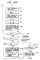
- Figs. 22A and 22B correspond to Figs. 15A and 15B in the above third embodiment in which the step #103 is changed to a step #1400, the step #1116 is changed to a step #1401, and the step #1121 is changed to a step #1402, respectively.
- the step #103 is changed to a step #1400
- the step #1116 is changed to a step #1401
- the step #1121 is changed to a step #1402, respectively.
- step #1400 of Figs. 22A and 22B communication with the CPU 11 within the interchangeable lens 8 is conducted to obtain data used for photometric operation such as photometry or release iris value, data for focal point adjustment such as the focal point adjustment sensitivity, and data corresponding to the blur prevention sensitivity.
- the blur prevention sensitivity is directed to a ratio of the coordinate position drive signal of the blur correction lens with respect to the inclined amount of the device as described above, which changes in accordance with a state of zoom and focus.
- the blur prevention sensitivity is used for arithmetic operation executed in the step #1151 shown in Fig. 18 which is described in the above.
- zoom information is employed as data corresponding to the blur prevention sensitivity.
- a manner of transmitting and receiving the information is that when a given data request signal is transmitted toward the interchangeable lens 8 from the camera body 1, the zoom information is transmitted to the camera body 1 side as the data corresponding to the blur prevention sensitivity in response to the given data request signal at the interchangeable lens 8 side.
- the data includes information related to a given-angle-of-view drive signal that drives to a given angle of view (which means an angle of an object to be photographed from the camera) which includes the angle-of-view setting information of the image blur correcting means that sets the position of the image blur correcting means in accordance with the received given-angle-of-view drive signal.
- the angle-of-view drive information can be employed with high efficiency by changing the drive angle of view of the image blur correcting means due to a difference in the focal distance of the lens, a difference in the blur prevention sensitivity and a difference in the drive range of the image blur correcting means, for example, even if the same given-angle-of-view drive signal is transmitted to the lens.
- the given-angle-of-view drive signal that drives the image blur correcting means to the initial angle of view or the center angle of view is transmitted to the lens.
- the image blur correcting means drive command in the yaw direction is 40 H and the image blur correcting means drive command in the pitch direction is 41 H, in order to drive the image blur correcting means to a certain coordinate position, it is necessary to transmit
- the angle of view can be set to 43H.
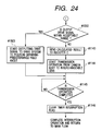
- Figs. 23 and 24 correspond to Figs. 16 and 17 in the above third embodiment in which the step #1133 is changed to a step #1500, the step #1134 is changed to a step #1501, the step #1141 is changed to a step #1502, and the step #1142 is changed to a step #1503, respectively.
- the step #1133 is changed to a step #1500
- the step #1134 is changed to a step #1501
- the step #1141 is changed to a step #1502
- the step #1142 is changed to a step #1503, respectively.
- 45H is +0.0256 degrees and 46H is +1.2287 degrees (the end portion on the optical performance, the end portion on the blur prevention control, or the like) in this example, it may be set to an
- step #1152 If it is judged that the data of the above step #1152 is equal to or close to those values, the control is advanced from the step #1500 to a step #1501 where the output of the given-angle-of-view drive signal of 1 byte starts, and the control is then advanced to a step #1137.
- the conditions where it is judged that those signals are close to each other are changed in accordance with the observing time, the photographing time, the zoom position, the focus position, the camera mode setting, other traffic and so on. Therefore, only the data transmission of 1 byte can be permitted as compared with the data transmission of 3 bytes (3 ⁇ 8 bits) conventionally required, thereby being capable of reducing the communication load.
- steps #1502 and #1503 of Fig. 24 are substantially the same operation as that of the step #1500 and #1501 of the above Fig. 23, although there are differences in the yaw and the pitch, their description will be omitted.
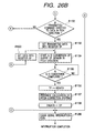
- Figs. 25, 26A and 26B correspond to Figs. 20, 21A and 21B in the above third embodiment in which the step #1199 is changed to a step #1600, the step #1200 is changed to a step #1601, the step #1201 is changed to a step #1602, the step #1202 is changed to a step #1603, the step #1203 is changed to a step #1604, and the step #1204 is changed to a step #1605, respectively.
- the step #1200 is changed to a step #1601
- the step #1201 is changed to a step #1602
- the step #1202 is changed to a step #1603
- the step #1203 is changed to a step #1604
- the step #1204 is changed to a step #1605, respectively.
- step #1600 of Figs. 26A and 26B it is judged whether the data is the given-angle-of-view drive signal in the yaw direction or not, and if so, the control is advanced to a step #1601 where the data corresponding to the given-angle-of-view drive signal in the yaw direction is set at the SY register within the CPU 11, and the control is advanced to a step #1187 of Fig. 25.
- step #1602 of Figs. 26A and 26B it is judged whether the data is the given-angle-of-view drive signal in the pitch direction or not, and if so, the control is advanced to a step #1603 where the data corresponding to the given-angle-of-view drive signal is set at the SP register within the CPU 11, and the control is advanced to step #1194.
- step #1604 If it is judged in step #1602 that the data is not the given-angle-of-view drive signal in the pitch direction, the control is advanced to a step #1604 where it is judged whether the data is the given-angle -of-view drive signal in the yaw direction, and if so, the control is advanced to step #1605 where the data corresponding to the given-angle-of-view drive signal is set at the SY register within the CPU 11, and the same operation as that of the steps #1187 to #1191 is executed, and the data corresponding to the given-angle-of-view drive signal is set at the SP register within the CPU 11, and the same operation as that of the steps #1194 to #1198 is executed.
- the image blur correcting means is driven by using the latter signal instead of the former signal. Therefore, the communication load can be reduced to 1/3 of the normal load during the communication under the above circumstances.
- steps #2160 and #2161 of Fig. 27 the correction arithmetic operation internal registers for lens control CY and CP are reset to 0H, respectively.
- the LCK flag indicative of the lock setting control is set to 0, and likewise in a step #2163, the ULCK flag indicative of the lock release control is set to 0.
- the interruption operation of a serial interface for receiving data transmitted from the camera body 1 as described above is permitted.
- a subsequent step #2165 it is judged whether the command previously received from the camera body 1 is a command or data related to the image blur correction such as a command for driving the blur correction lens 54 (in more detail, which is an image blur correcting means made up of the blur correction lens 54 and its support member) or not, and if so, the control is advanced to a step #2166 where a timer TMRHOSEI is reset and started, and the control is advanced to a step #2170.
- a command or data related to the image blur correction such as a command for driving the blur correction lens 54 (in more detail, which is an image blur correcting means made up of the blur correction lens 54 and its support member) or not, and if so, the control is advanced to a step #2166 where a timer TMRHOSEI is reset and started, and the control is advanced to a step #2170.
- the control is advanced to a step #2167 from the step #2165 where it is judged whether a value of the timer TMRHOSEI is larger than a predetermined period of time TMRHOSEIDEF or not, and if larger, since the command or data related to the image blur correction has not been received for the predetermined period of time (TMRHOSEIDEF), the control is advanced to a step #2168 in order to stop the driving of the image blur correcting means where the lock operation is conducted.
- the blur correction lens 54 is moved to a lockable position in accordance with a control signal from the CPU 11, and a current is supplied to the plunger 58 in the mechanical lock mechanism by the actuator driver circuit 17 of the mechanical lock mechanism, to thereby forcedly stop the movement of the blur correction lens 54 by a lever. Then, the control is advanced to a step #2169 where the flag LCK is set to 0, and the control is advanced to a step #2170.
- the above operation may be identical with the operation of a step #2174 which will be described later, but the image blur correcting means may be driven with an electric power that reduces the power consumption or may be driven for a shorter period of time, taking into consideration that more electric power is required due to a frictional force or a loss of a coil resistance is applied if the image blur correcting means is moved more quickly.
- the control is advanced to a step #2170 where it is judged whether a command that accelerates the lock release has been received during the serial interface communication interruption operation which will be described later or not, and if the flag ULCK is 0, the control is advanced to a step #2173 as it is, assuming that the lock release command has not been received.
- the control is advanced to a step #2171 from the step #2170 assuming that the lock release command has been received, and the lock release operation is immediately conducted.
- the blur correction lens 54 is moved to a lockable position in accordance with a control signal from the CPU 11, and a current is supplied to the plunger 58 in the mechanical lock mechanism shown in Fig. 3 in a given direction by the actuator driver circuit 17 of the mechanical lock mechanism through a mechanical lock driver not shown, to thereby release the engagement of the blur correction lens 54 which is a shift lens.
- the above-mentioned flag ULCK is set to 0.
- a subsequent step #2173 it is judged whether the flag LCK indicative of the lock setting is 1 or not, and if the flag LCK is 0, the control is returned to the step #2164 as it is, assuming that the lock setting command has not been received.
- the flag LCK is 1
- the control is advanced to a step #2174 assuming that the lock setting command has been received, and the lock setting operation is immediately conducted.
- a current is supplied to the plunger 58 in the mechanical lock mechanism in a counter direction to that in case of lock release by the actuator driver circuit 17 of the mechanical lock mechanism in accordance with a control signal from the CPU 11, to thereby forcedly stop the movement of the blur correction lens 54 by a lever.
- the flag LCK is set to 0 in the step #2175, and the control is returned to the step #2164 again, to thereby repeat the above-mentioned operation.
- step #2167 even if the driving of the image blur correcting means stops without receiving the command or data related to the image blur correction for a given period of time in step #2167, if the command or data related to the image blur correction is received again, the image blur correcting means is driven.
- the command or data related to the driving of the blur correction lens 54 from the camera body 1 side to the interchangeable lens 8 side does not occur for a given period of time (not received by the interchangeable lens 8) as shown in the steps #2167 to #2169 of Fig. 27, since the driving of the image blur correcting means is locked at a given position by locking means made up of a mechanical structure, the useless driving of the image blur correcting means is prevented, thereby being capable of suppressing the power consumption related to the blur correction to substantially 0.
- Fig. 28 is a flowchart showing a main process of an interchangeable lens in accordance with a sixth embodiment of the present invention, which corresponds to the flowchart of Fig. 27 in the above-described fifth embodiment. Since other parts are identical with those in the above-mentioned first embodiment, their description will be omitted.
- step #2167 it is judged whether the value of the timer TMRHOSEI is larger for a given period of time TMRHOSEIDEF as described above, and if larger, since the command or data related to the image blur correction has not been received for the predetermined period of time TMRHOSEIDEF, the control is advanced to a step #2260 in order to stop the driving of the image blur correcting means, where the blur correction lens 54 is driven to the given position and then stopped at that position.
- the blur correction lens 54 stops in that state, that the blur correction lens 54 stops at a movable center position, that the blur correction lens 54 stops after the retained energy is driven to a minimum position (a position where the blur correction lens or the like drops due to the gravity from the movable center position), and so on. Also, in order to stop the blur correction lens 54 at this position, it is necessary to continuously output the drive signal in the pitch and yaw directions to the driving means formed of a coil and so on for driving the blur correction lens (such means for retaining the blur correction lens at a given position by energization is called "electrically locking means"). In this case, the power consumption is slight, and the power consumption can be reduced more than that at the normal blur correction time.
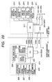
- Fig. 29 is a diagram showing a camera system in accordance with a seventh embodiment of the present invention, specifically a block diagram showing the electric structure of a state where an interchangeable lens equipped with the image blur correcting means is attached onto the camera body.
- reference numeral 2201 denotes a lens CPU that receives communication from the camera body side through communication contacts 2209c (for a clock signal) and 2209d (for signal transmission from the camera body to the lens signal), and actuates a blur correction system 2202, a zoom driving system 2203, a focus driving system 2204 and an aperture stop driving system 2205 in accordance with a command value from the camera body side or controls a blur correction system 2202.
- the blur correction system 2202 is made up of a fluctuation sensor 2206 for detecting the blur or fluctuation, a signal processing system 2207 for conducting feedback control on the basis of a signal from the blur sensor 2206, and a blur correction lens 2208 for conducting an actual blur correcting operation in accordance with a control signal from the signal processing system 2207 (the image blur correcting means is made up of the blur correction lens 2208 and its support member).
- the zoom drive system 2203 drives a lens barrel that changes a focal distance of the lens in accordance with the command value from the CPU 2201 or upon depression of a switch not shown by an operator.
- the lens for adjustment of a focal point is driven in accordance with a command value from the CPU 2201 to conduct focusing.
- the aperture stor driving system 2205 closes the iris or stop to a set position in accordance with the command value from the CPU 2201 or returns the iris to an open state.
- the CPU 2201 transmits a state of the interior of the lens (states of the zoom position, the focus position, the iris value, etc.) and information related to the lens (data necessary for calculation of the release iris value, the focal distance and the distance measuring calculation, etc.) to the camera body side through the communication contact 2209e (for transmissing the signal from the interchangeable lens to the camera body), likewise.
- a lens electric system 2210 is made up of the CPU 2201, the blur correction system 2202, the zoom driving system 2203, the focus driving system 2204 and the aperture driving system 2205, and a current is supplied to the lens electric system 2210 from a power supply 2218 within the camera body through a mount portion contact 2209a and a GND contact 2209b.
- the interior of the camera body includes, as an electric system 2211 within the body, a distance measuring portion 2212, a photometry portion 2213, a shutter portion 2214, a display portion 2215, another control portion 2216 as well as a camera CPU 2217 for conducting management such as start or stop of those operation, exposure calculation, distance measuring calculation and so on.
- the electric power is supplied to the above electric system 2211 within the body from the power supply 2218 within the body.
- reference numeral 2221 denotes a switch that conducts photometry and range finding
- 2222 is a release switch.
- Those switches 2221 and 2222 are generally formed of two-stage stroke switches which are structured so that the switch SW1 turns on by a first stroke of the release bottom, and the switch SW2 turns on by a second stroke.
- Reference numeral 2223 denotes an exposure mode select switch, and the mode change may be conducted by turning on or of the switch 2223 or by operating the switch 2223 and another operating member at the same time.
- the blur correction system 2202 is equipped within the interchangeable lens side in Fig. 29.
- an adaptor may be disposed between the camera body and the interchangeable lens.
- the structure of the blur correction system 202 may be identical with, for example, that shown in Fig. 3.
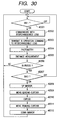
- a state of the switch SW1 is detected, and if the switch SW1 is off, the control remains in this step, and thereafter if the switch SW1 turns on, the control is advanced to a step #2302.
- the CPU 2217 conducts the communication with the interchangeable lens. This communication is made to obtain information necessary to conduct AE and AF, and when the CPU 217 transmits a communication command to the CPU 2201 equipped within the interchangeable lens, the CPU 2201 transmits information such as the focal distance, the AF sensitivity or the open F number.
- an IS actuation start command is transmitted to the interchangeable lens side.
- the sub-routine such as known photometry and distance measurement is executed.
- step #2306 it is judged whether it is in-focus or not, and if not in-focus, the control is returned to the step #2301, and the same operation is repeated.
- step #2307 the control is advanced to a step #2307 from the step #2306 where it is judged whether the switch SW2 is on or not, and if off, the control is returned to the step #2301, but if on, the control is advanced to a step #2308 where the mirror-up operation is conducted.
- step #2309 the leading curtain of the shutter not shown runs through the shutter portion 2214, to thereby start the exposure.
- step #2310 the exposure is conducted for only a set shutter speed time, and thereafter the control is advanced to a step #2311 where the trailing curtain of the shutter runs to complete the exposure.
- step #2312 mirror-down operation is conducted to complete sequential photographing operation.
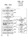
- a step #2321 in the communication for AE and AF shown in the step #2302 of Fig. 30, upon receiving the communication command from the CPU 2217 equipped in the camera body, the CPU 2201 transmits the information such as the focal distance, the AF sensitivity or the open F number. Then, in a subsequent step #2322, the measured distance is calculated by the CPU 2217, and the focal point adjustment lens is driven on the basis of the transmitted focal point adjustment lens moving amount.
- a subsequent step #2323 the reception of the IS actuation command is detected, and if the IS actuation command is not received, the control is advanced to a step #2325 where the reception of the IS stop command is detected.
- the control is immediately advanced to a step #2340, but if the IS stop command is not received, the control is advanced to a step #2339 where it is judged whether the timer TMRHOSEI is larger than a predetermined period of time TMRHOSEIDEF or not. If smaller, the control is returned to the step #2321.
- the control is advanced to a step #2340 from the step #2339, and since the command or data related to the image blur correction has not been received for the predetermined period of time TMRHOSEIDEF, the blur correction lens 2208 is driven to a predetermined lockable position in order to stop the driving of the image blur correction lens 2208.
- the locking operation is conducted. Specifically, a current is supplied to the plunger 58 in the mechanical lock mechanism, for example, shown in Fig. 3 by the actuator driver circuit of the mechanical lock mechanism (included in the signal processing system 2207 in Fig. 29), to thereby forcedly stop the movement of the blur correction lens 54 by a lever.
- the control is advanced to a step #2324 where the timer TMRHOSEI is reset and starts. Then, in a subsequent step #2326, the blur sensor output and the blur correction amount are read, and in a subsequent step #2327, the data is subjected to A/D conversion, and in a subsequent step #2328, the data is converted into driving data for conversion of the blur correction lens 2208. Then, in a step #2329, the blur correction lens 2208 is driven to conduct blur correction.
- a subsequent step #2330 the reception of the on signal of the switch SW2 is detected, and upon receiving the on signal, the control is advanced to a step #2331 where the blur sensor output and the blur correction amount are read, and in a subsequent step #2332, the data is subjected to A/D conversion. Then, in a subsequent step #2333, mirror and shutter fluctuation data stored in a ROM is read, and in a subsequent step #2334, the data is converted into data for driving the blur correction lens 2208, and in a step #2335, the blur correction lens 2208 is driven to conduct blur correction.
- step #2336 the iris is closed through the aperture stop driving system 2205 to conduct the exposure, and in a step #2337, if the completion of exposure is not detected, the control is returned to the step #2331, but if the completion of exposure is detected, the control is advanced to a step #2338 where the iris is released to complete the sequential operation, and the control is returned to the step #2321.
- the driving of the blur correcting means is locked at the given position by the locking means formed of a mechanical structure, the useless driving of the image blur correcting means is prevented, thereby being capable of suppressing the power consumption caused by the blur correction during that period of time to 0.
- Figs. 32A and 32B are flowcharts showing the operation at the interchangeable lens side in accordance with an eighth embodiment of the present invention, and corresponds to the flowchart shown in Figs. 31A and 31B in accordance with the above seventh embodiment. Since other operation is identical with that in the above seventh embodiment, its description will be omitted.
- a step #2400 is added.
- step #2339 it is judged whether the timer TMRHOSEI is larger than a predetermined period of time TMRHOSEIDEF or not, and if larger, since the command or data related to the image blur correction has not been received for the predetermined period of time TMRHOSEIDEF, the control is advanced to a step #2400 in order to stop the driving of the blur correction lens 2208, where the blur correction lens 2208 is driven to a given position and stops.
- the stopping manner is identical with that in the above seventh embodiment.
- the power consumption related to the driving of the image blur correcting means can be reduced as in the above seventh embodiment.
- the blur or fluctuation sensor formed of a vibration gyro is assumed as the blur detecting means, however other angular velocity sensors or other sensors (displacement or angular velocity sensor, velocity sensor, acceleration, or angular acceleration sensor, an area sensor, etc.) can be used.
- the image blur correcting means an optical member is moved on a face substantially perpendicular to the optical axis, to thereby conduct the image blur correction.
- other image blur correcting means such as a variable apex angle prism or the like may be employed.
- the present invention is applied to a silver salt camera.
- the present invention can be applied to another photographing device such as a video camera or a digital camera, or other optical devices.
- the image blur correcting system formed of the photographing device and the optical device which is capable of reducing the arithmetic operation load related to the image blur correction at the optical device side.
- the image blur correcting system the camera system the camera and the interchangeable lens which are capable of reducing the communication load related to the load of driving the image blur correcting means depending on the drive target position of the image blur correcting means.
- the image blur correcting system the camera system the camera and the interchangeable lens which are capable of suppressing the power consumption or reducing the power consumption by stopping the useless driving of the image blur correcting means if a signal related to the driving of the image blur correcting means does not occur for a predetermined period of time.
- An image blur correcting system includes a photographing device including arithmetically operating means for determining a relation between a detection output value of the blur detecting means and a driven amount of the image blur correcting means corresponding to the detection output value in accordance with information related to a blur prevention sensitivity, conducting arithmetic operation on the basis of the determined relation to calculate a drive signal for driving the image blur correcting means in accordance with the detection output value of the blur detecting means, and transmitting means for transmitting the drive signal calculated by the arithmetically operating means to the optical device, and an optical device including transmitting means for transmitting the information related to the blur prevention sensitivity to the photographing device, and drive control means that receives the drive signal for controlling the driving of the image blur correcting means in accordance with the drive signal.
Landscapes
- Physics & Mathematics (AREA)
- General Physics & Mathematics (AREA)
- Optics & Photonics (AREA)
- Adjustment Of Camera Lenses (AREA)
- Structure And Mechanism Of Cameras (AREA)
Abstract
Description
the interchangeable lens comprising:
transmitting means for transmitting to the interchangeable lens a given-position drive signal for driving the image blur correcting means to a given position or a coordinate position drive signal of the image blur correcting means which is calculated on the basis of an output of the blur detecting means.
drive control means for controlling the driving of the image blur correcting means in accordance with the given-position drive signal transmitted from the camera or the coordinate position drive signal.
transmitting means for transmitting to the interchangeable lens a given-angle-of-view drive signal for driving the image blur correcting means to a given angle of view or a coordinate position drive signal of the image blur correcting means which is calculated on the basis of an output of the blur detecting means.
drive control means for controlling the driving of the image blur correcting means in accordance with the given-angle-of-view drive signal transmitted from the camera or the coordinate position drive signal.
drive control means for controlling the driving of the image blur correcting means on the basis of the signal related to the driving of the image blur correcting means upon receiving the signal from the camera and for stopping the driving of the image blur correcting means when not receiving the signal related to the driving of the image blur correcting means for a predetermined period of time.
drive control means for controlling the driving of the image blur correcting means on the basis of the signal related to the driving of the image blur correcting means upon receiving the signal, and for driving the image blur correcting means to a predetermined position and stopping the driving of the image blur correcting means when not receiving the signal related to the driving of the image blur correcting means for a predetermined period of time.
| 40H, 00H, 00H (0) | 0 degree (angle of view) |
| 41H, 00H, 00H (0) | 0 degree (angle of view) |
| 44H = 40H, 00H, 00H (0) | 0 degree |
| 45H = 40H, 01H, 00H (+256) | 0.0256 degrees |
| 46H = 40H, 2FH, FFH (+12287) | 1.2287 degrees |
| 47H = 40H, FFH, 00H (-256) | -0.0256 degrees |
| 48H = 40H, D0H, 00H (-12288) | -1.2288 degrees |
| 44H = 40H, 00H, 00H (0) | 0 degree |
| 45H = 40H, 01H, 00H (+256) | 0.0256 degrees |
| 46H = 40H, 2FH, FFH (+12287) | 1.2287 degrees |
| 47H = 40H, FFH, 00H (-256) | -0.0256 degrees |
| 48H = 40H, DOH, 00H (-12288) | -1.2288 degrees |
Claims (47)
- An image blur correcting system formed of the combination of a photographing device having blur detecting means and an optical device having image blur correcting means, whereinsaid photographing device comprising:arithmetically operating means for determining a relation between a detection output value of said blur detecting means and a driven amount of said image blur correcting means corresponding to the detection output value in accordance with information related to a blur prevention sensitivity, conducting arithmetic operation on the basis of the determined relation to calculate a drive signal for driving said image blur correcting means in accordance with the detection output value of said blur detecting means; andtransmitting means for transmitting the drive signal calculated by said arithmetically operating means to said optical device, andsaid optical device comprising:transmitting means for transmitting the information related to the blur prevention sensitivity to said photographing device; anddrive control means that receives the drive signal for controlling the driving of said image blur correcting means in accordance with the drive signal.
- An image blur correcting system according to claim 1, wherein said optical device includes at least one of a focus lens and a zoom lens, and said transmitting means transmits a signal corresponding to a state of at least one of said focus lens and said zoom lens to said photographing device as the information related to the blur prevention sensitivity.
- An image blur correcting system according to claim 2, wherein said transmitting means transmits the signal corresponding to a state of at least one of said focus lens and said zoom lens to said photographing device as the information related to the blur prevention sensitivity after said focus lens is in focus.
- An image blur correcting system according to claim 1, wherein said arithmetically operating means equipped in said photographing device determines a relation between the detection output value of said blur detecting means and the driven amount of said image blur correcting means in accordance with the information related to the blur prevention sensitivity which is transmitted from said optical device and conducts arithmetic operation for calculating the drive signal, at any time while the image blur correcting operation continues.
- An image blur correcting system according to claim 1, wherein said transmitting means equipped in said optical device transmits the information related to the blur prevention sensitivity to said photographing device upon receiving the drive signal from said photographing device.
- A camera system formed of the combination of a camera having blur detecting means and an interchangeable lens having image blur correcting means, whereinsaid camera comprising:arithmetically operating means for determining a relation between a detection output value of said blur detecting means and a driven amount of said image blur correcting means corresponding to the detection output value in accordance with information related to a blur prevention sensitivity, conducting arithmetic operation on the basis of the determined relation to calculate a drive signal for driving said image blur correcting means in accordance with the detection output value of said blur detecting means; andtransmitting means for transmitting the drive signal calculated by said arithmetically operating means to said interchangeable lens, andsaid interchangeable lens comprising:transmitting means for transmitting the information related to the blur prevention sensitivity to said camera; anddrive control means that receives the drive signal for controlling the driving of said image blur correcting means in accordance with the drive signal.
- A camera having blur detecting means used in combination with an interchangeable lens having image blur correcting means, said camera comprising:arithmetically operating means for determining a relation between a detection output value of said blur detecting means and a driven amount of said image blur correcting means corresponding to the detection output value in accordance with information related to a blur prevention sensitivity, conducting predetermined arithmetic operation on the basis of the determined relation to calculate a drive signal for driving said image blur correcting means in accordance with the detection output value of said blur detecting means; andtransmitting means for transmitting the drive signal calculated by said arithmetically operating means to said interchangeable lens.
- An interchangeable lens having image blur correcting means used in combination with a camera having blur detecting means, said interchangeable lens comprising:transmitting means for transmitting information related to the blur prevention sensitivity to said camera; anddrive control means for controlling the driving of said image blur correcting means in accordance with the drive signal transmitted from said camera.
- An image blur correcting system formed of the combination of a photographing device having blur detecting means with an optical device having image blur correcting means,said photographing device comprising: transmitting means for transmitting to said optical device a given-position drive signal for driving said image blur correcting means to a given position or a coordinate position drive signal of said image blur correcting means which is calculated on the basis of an output of said blur detecting means; andsaid optical device comprising: drive control means for controlling the driving of said image blur correcting means in accordance with the given-position drive signal transmitted from said transmitting means or the coordinate position drive signal.
- An image blur correcting system according to claim 9, wherein the data amount of the given-position drive signal is smaller than the data amount of the coordinate position drive signal.
- An image blur correcting system according to claim 9, wherein said photographing device transmits the given-position drive signal to said optical device from said transmitting means instead of the coordinate position drive signal in the case where the coordinate position drive signal calculated on the basis of an output of said blur detecting means is equal to or substantially equal to the given-position drive signal.
- An image blur correcting system according to claim 9, wherein said optical device transmits position setting information related to the given-position drive signal to which the optical characteristic of said optical device is added to said photographing device; and
wherein said photographing device transmits the given-position drive signal for driving said image blur correcting means to a predetermined position to said optical device on the basis of the position setting information. - An image blur correcting system formed of the combination of a photographing device having blur detecting means with an optical device having image blur correcting means,said photographing device comprising: transmitting means for transmitting to said optical device a given-angle-of-view drive signal for driving said image blur correcting means to a given angle of view or a coordinate position drive signal of said image blur correcting means which is calculated on the basis of an output of said blur detecting means; andsaid optical device comprising: drive control means for controlling the driving of said image blur correcting means in accordance with the given-angle-of-view drive signal transmitted from said transmitting means or the coordinate position drive signal.
- An image blur correcting system according to claim 13, wherein the data amount of the given-angle-of-view drive signal is smaller than the data amount of the coordinate position drive signal.
- An image blur correcting system according to claim 13, wherein said photographing device transmits the given-angle-of-view drive signal to said optical device from said transmitting device instead of the coordinate position drive signal in the case where the coordinate position drive signal calculated on the basis of an output of said blur detecting means is equal to or substantially equal to the given-angle-of-view drive signal.
- An image blur correcting system according to claim 13, wherein said optical device transmits position setting information related to the given-position drive signal to which the optical characteristic of said optical device is added to said photographing device; and
wherein said photographing device transmits the given-angle-of-view drive signal for driving said image blur correcting means to a predetermined position to said optical device on the basis of the position setting information. - An image blur correcting system according to claim 13, wherein said optical device comprises an interchangeable lens.
- A camera system formed of the combination of a camera having blur detecting means with an interchangeable lens having image blur correcting means,said camera comprising: transmitting means for transmitting to said interchangeable lens a given-position drive signal for driving said image blur correcting means to a given position or a coordinate position drive signal of said image blur correcting means which is calculated on the basis of an output of said blur detecting means; andsaid interchangeable lens comprising: drive control means for controlling the driving of said image blur correcting means in accordance with the given-position drive signal transmitted from said transmitting means or the coordinate position drive signal.
- A camera system according to claim 18, wherein the data amount of the given-position drive signal is smaller than the data amount of the coordinate position drive signal.
- A camera system according to claim 18, wherein said camera transmits the given-position drive signal to said interchangeable lens from said transmitting device instead of the coordinate position drive signal in the case where the coordinate position drive signal calculated on the basis of an output of said blur detecting means is equal to or substantially equal to the given-position drive signal.
- An image blur correcting system according to claim 18, wherein said interchangeable lens transmits position setting information related to the given-position drive signal to which the optical characteristic of said optical device is added to said camera; and
wherein said camera transmits the given-position drive signal for driving said image blur correcting means to a predetermined position to said interchangeable lens on the basis of the position setting information. - A camera having blur detecting means that constitutes a camera system in combination with an interchangeable lens having image blur correcting means, said camera comprising:
transmitting means for transmitting to said interchangeable lens a given-position drive signal for driving said image blur correcting means to a given position or a coordinate position drive signal of said image blur correcting means which is calculated on the basis of an output of said blur detecting means. - An camera system according to claim 22, wherein said camera transmits the given-position drive signal to said interchangeable lens from said transmitting device instead of the coordinate position drive signal in the case where the coordinate position drive signal calculated on the basis of an output of said blur detecting means is equal to or substantially equal to the given-position drive signal.
- An interchangeable lens constituting a camera system in combination with said camera according to claim 22 or 23, said interchangeable lens comprising:
drive control means for controlling the driving of said image blur correcting means in accordance with the given-position drive signal transmitted from said camera or the coordinate position drive signal. - A camera system formed of the combination of a camera having blur detecting means with an interchangeable lens having image blur correcting means,said camera comprising: transmitting means for transmitting to said optical device a given-angle-of-view drive signal for driving said image blur correcting means to a given angle of view or a coordinate position drive signal of said image blur correcting means which is calculated on the basis of an output of said blur detecting means; andsaid interchangeable lens comprising: drive control means for controlling the driving of said image blur correcting means in accordance with the given-angle-of-view drive signal transmitted from said transmitting means or the coordinate position drive signal.
- A camera system according to claim 25, wherein the data amount of the given-angle-of-view drive signal is smaller than the data amount of the coordinate position drive signal.
- A camera system according to claim 25, wherein said camera transmits the given-angle-of-position drive signal to said interchangeable lens from said transmitting device instead of the coordinate position drive signal in the case where the coordinate position drive signal calculated on the basis of an output of said blur detecting means is equal to or substantially equal to the given-angle-of-position drive signal.
- A camera system according to claim 25, wherein said interchangeable lens transmits position setting information related to the given-position drive signal to which the optical characteristic of said optical device is added to said camera; and
wherein said camera transmits the given-angle-of-view drive signal for driving said image blur correcting means to a predetermined position to said interchangeable lens, on the basis of the position setting information. - A camera having blur detecting means which constitutes a camera system in combination with an interchangeable lens having image blur correcting means, said camera comprising:
transmitting means for transmitting to said interchangeable lens a given-angle-of-view drive signal for driving said image blur correcting means to a given angle of view or a coordinate position drive signal of said image blur correcting means which is calculated on the basis of an output of said blur detecting means. - A camera according to claim 29, wherein said camera transmits the given-angle-of-position drive signal to said interchangeable lens from said transmitting device instead of the coordinate position drive signal in the case where the coordinate position drive signal calculated on the basis of an output of said blur detecting means is equal to or substantially equal to the given-angle-of-position drive signal.
- An interchangeable lens having image blur correcting means which constitutes a camera system in combination with said camera according to claim 29, said interchangeable lens comprising:drive control means for controlling the driving of said image blur correcting means in accordance with the given-angle-of-view drive signal transmitted from said camera or the coordinate position drive signal.
- An image blur correcting system formed of the combination of a photographing device having blur detecting means with an optical device having image blur correcting means,said photographing device comprising: transmitting means for transmitting a signal related to the driving of said image blur correcting means to said optical device; andsaid optical device comprising: drive control means for controlling the driving of said image blur correcting means on the basis of the signal related to the driving of said image blur correcting means upon receiving said signal and for stopping the driving of said image blur correcting means when not receiving the signal related to the driving of said image blur correcting means for a predetermined period of time.
- An image blur correcting system according to claim 32, wherein said optical device includes mechanically locking means for mechanically locking said image blur correcting means to a given position; and
wherein said drive control means locks said image blur correcting means to a given position by said mechanically locking means after said image blur correcting means is driven to a position where said mechanically locking means functions when said drive control means does not receive the signal related to the driving for a predetermined period of time. - An image blur correcting system formed of the combination of a photographing device having blur detecting means with an optical device having image blur correcting means,said photographing device comprising: transmitting means for transmitting a signal related to the driving of said image blur correcting means to said optical device; andsaid optical device comprising: drive control means for controlling the driving of said image blur correcting means on the basis of the signal related to the driving of said image blur correcting means upon receiving said signal, and for driving said image blur correcting means to a predetermined position and stopping the driving of said image blur correcting means when not receiving the signal related to the driving of said image blur correcting means for a predetermined period of time.
- An image blur correcting system according to claim 34, wherein said image blur correcting means includes electrically locking means for retaining said image blur correcting means to said predetermined position.
- An image blur correcting system according to claim 34, wherein said predetermined position is a position at the time where it is judged that the signal related to the driving is not received for said predetermined period of time.
- An image blur correcting system according to claim 34 or 35, wherein said predetermined position is a movable center position of said image blur correcting means.
- An image blur correcting system according to claim 34 or 35, wherein said predetermined position is a position where an electric power for retaining said image blur correcting means to a predetermined position is the least.
- A camera system formed of the combination of a camera having blur detecting means with an interchangeable lens having image blur correcting means,said camera comprising: transmitting means for transmitting a signal related to the driving of said image blur correcting means to said camera; andsaid interchangeable lens comprising: drive control means for controlling the driving of said image blur correcting means on the basis of the signal related to the driving of said image blur correcting means upon receiving said signal and for stopping the driving of said image blur correcting means when not receiving the signal related to the driving of said image blur correcting means for a predetermined period of time.
- An camera system according to claim 39, wherein said interchangeable lens includes mechanically locking means for mechanically locking said image blur correcting means to a given position; and
wherein said drive control means locks said image blur correcting means to a given position by said mechanically locking means after said image blur correcting means is driven to a position where said mechanically locking means functions when said drive control means does not receive the signal related to the driving for a predetermined period of time. - A camera system formed of the combination of a camera having blur detecting means with an interchangeable lens having image blur correcting means,said camera comprising: transmitting means for transmitting a signal related to the driving of said image blur correcting means to said optical device; andsaid interchangeable lens comprising: drive control means for controlling the driving of said image blur correcting means on the basis of the signal related to the driving of said image blur correcting means upon receiving said signal and for driving said image blur correcting means to a predetermined position and stopping the driving of said image blur correcting means when not receiving the signal related to the driving of said image blur correcting means for a predetermined period of time.
- A camera system according to claim 41, wherein said image blur correcting means includes electrically locking means for retaining said image blur correcting means to said predetermined position.
- A camera system according to claim 41, wherein said predetermined position is a position at the time where it is judged that the signal related to the driving is not received for said predetermined period of time.
- A camera system according to claim 41 or 42, wherein said predetermined position is a movable center position of said image blur correcting means.
- A camera system according to claim 41 or 42, wherein said predetermined position is a position where an electric power for retaining said image blur correcting means to a predetermined position is the least.
- An interchangeable lens having image blur correcting means which constitutes a camera system in combination with a camera having blur detecting means, said interchangeable lens comprising:
drive control means for controlling the driving of said image blur correcting means on the basis of the signal related to the driving of said image blur correcting means upon receiving said signal from said camera, and for stopping the driving of said image blur correcting means when not receiving the signal related to the driving of said image blur correcting means for a predetermined period of time. - An interchangeable lens having image blur correcting means which constitutes a camera system in combination with a camera having blur detecting means, said interchangeable lens comprising:
drive control means for controlling the driving of said image blur correcting means on the basis of the signal related to the driving of said image blur correcting means upon receiving said signal, and for driving said image blur correcting means to a predetermined position and stopping the driving of said image blur correcting means when not receiving the signal related to the driving of said image blur correcting means for a predetermined period of time.
Applications Claiming Priority (6)
| Application Number | Priority Date | Filing Date | Title |
|---|---|---|---|
| JP37318599 | 1999-12-28 | ||
| JP37318599A JP4677074B2 (en) | 1999-12-28 | 1999-12-28 | Camera system and camera |
| JP2000235066 | 2000-08-03 | ||
| JP2000235066A JP2002049066A (en) | 2000-08-03 | 2000-08-03 | Image stabilization system, camera system and interchangeable lens |
| JP2000253039 | 2000-08-23 | ||
| JP2000253039A JP2002072272A (en) | 2000-08-23 | 2000-08-23 | Image stabilization system, camera system, camera and interchangeable lens |
Publications (3)
| Publication Number | Publication Date |
|---|---|
| EP1122581A2 true EP1122581A2 (en) | 2001-08-08 |
| EP1122581A3 EP1122581A3 (en) | 2001-08-22 |
| EP1122581B1 EP1122581B1 (en) | 2004-08-04 |
Family
ID=27341827
Family Applications (1)
| Application Number | Title | Priority Date | Filing Date |
|---|---|---|---|
| EP00128542A Expired - Lifetime EP1122581B1 (en) | 1999-12-28 | 2000-12-27 | Image blur correcting system |
Country Status (3)
| Country | Link |
|---|---|
| US (1) | US6522837B2 (en) |
| EP (1) | EP1122581B1 (en) |
| DE (1) | DE60012683T2 (en) |
Cited By (2)
| Publication number | Priority date | Publication date | Assignee | Title |
|---|---|---|---|---|
| EP1351526A3 (en) * | 2002-04-03 | 2005-02-02 | Fuji Photo Optical Co., Ltd. | Lens apparatus diagnostic system |
| EP1630595A1 (en) * | 2004-08-27 | 2006-03-01 | Fujinon Corporation | Photographic apparatus and interchangeable camera lens with blur compensation means |
Families Citing this family (6)
| Publication number | Priority date | Publication date | Assignee | Title |
|---|---|---|---|---|
| JP2004301939A (en) * | 2003-03-28 | 2004-10-28 | Sony Corp | Camera system, camera, and interchangeable lens |
| JP4347288B2 (en) * | 2005-11-07 | 2009-10-21 | キヤノン株式会社 | Imaging device |
| JP4778852B2 (en) * | 2006-07-13 | 2011-09-21 | Hoya株式会社 | Image blur correction device |
| JP5237978B2 (en) * | 2010-02-12 | 2013-07-17 | パナソニック株式会社 | Imaging apparatus and imaging method, and image processing method for the imaging apparatus |
| JP2013219544A (en) * | 2012-04-09 | 2013-10-24 | Ricoh Co Ltd | Image processing apparatus, image processing method, and image processing program |
| JP6090636B2 (en) * | 2014-02-28 | 2017-03-08 | パナソニックIpマネジメント株式会社 | Blur correction device, lens barrel including the same, and camera system |
Family Cites Families (9)
| Publication number | Priority date | Publication date | Assignee | Title |
|---|---|---|---|---|
| JP2961761B2 (en) * | 1989-09-14 | 1999-10-12 | ミノルタ株式会社 | Optical device |
| US5172150A (en) | 1989-10-04 | 1992-12-15 | Minolta Camera Kabushiki Kaisha | Apparatus for correcting image blur caused by camera shake |
| JPH06250272A (en) | 1993-02-24 | 1994-09-09 | Canon Inc | Image blur preventive system |
| JP3513950B2 (en) | 1993-12-14 | 2004-03-31 | 株式会社ニコン | Image stabilization camera |
| JPH07191355A (en) | 1993-12-27 | 1995-07-28 | Canon Inc | Control device for image blur prevention |
| JPH07191354A (en) * | 1993-12-27 | 1995-07-28 | Canon Inc | Transmitter for image stabilization system |
| US6097896A (en) * | 1997-08-25 | 2000-08-01 | Nikon Corporation | Motion compensation system having motion detection signal correction |
| JP3870501B2 (en) | 1997-08-25 | 2007-01-17 | 株式会社ニコン | Blur correction device and optical device |
| JP3948065B2 (en) | 1997-08-25 | 2007-07-25 | 株式会社ニコン | Blur correction device, optical device, and blur correction method |
-
2000
- 2000-12-19 US US09/739,215 patent/US6522837B2/en not_active Expired - Lifetime
- 2000-12-27 EP EP00128542A patent/EP1122581B1/en not_active Expired - Lifetime
- 2000-12-27 DE DE60012683T patent/DE60012683T2/en not_active Expired - Lifetime
Cited By (4)
| Publication number | Priority date | Publication date | Assignee | Title |
|---|---|---|---|---|
| EP1351526A3 (en) * | 2002-04-03 | 2005-02-02 | Fuji Photo Optical Co., Ltd. | Lens apparatus diagnostic system |
| US7149423B2 (en) | 2002-04-03 | 2006-12-12 | Fujinon Corporation | Lens apparatus diagnostic system, diagnostic program, record medium, lens diagnostic system and controller diagnostic system |
| EP1630595A1 (en) * | 2004-08-27 | 2006-03-01 | Fujinon Corporation | Photographic apparatus and interchangeable camera lens with blur compensation means |
| US7756406B2 (en) | 2004-08-27 | 2010-07-13 | Fujinon Corporation | Photographic apparatus and interchangeable camera lens |
Also Published As
| Publication number | Publication date |
|---|---|
| EP1122581A3 (en) | 2001-08-22 |
| DE60012683T2 (en) | 2005-07-28 |
| DE60012683D1 (en) | 2004-09-09 |
| US6522837B2 (en) | 2003-02-18 |
| US20010031141A1 (en) | 2001-10-18 |
| EP1122581B1 (en) | 2004-08-04 |
Similar Documents
| Publication | Publication Date | Title |
|---|---|---|
| JP2887061B2 (en) | Apparatus for preventing image blur | |
| EP1122581B1 (en) | Image blur correcting system | |
| US4908647A (en) | Lens driving device | |
| US6088533A (en) | Transmission apparatus for image blur prevention | |
| US6035133A (en) | Image blur prevention device | |
| US7057644B2 (en) | Camera system, camera, and lens apparatus with variable length vibration correction data | |
| JP3897592B2 (en) | Camera system | |
| US5079581A (en) | Automatic focus adjusting apparatus | |
| JP3195483B2 (en) | Camera image stabilizer | |
| JPH06308564A (en) | Image blurring correcting device | |
| JP4756789B2 (en) | Image stabilization system | |
| JPH07199262A (en) | Camera with image stabilization function | |
| JP2003195383A (en) | Imaging system and camera | |
| JP4677074B2 (en) | Camera system and camera | |
| JP3038609B2 (en) | Camera with variable focus lens that can change the distance measurement direction | |
| JP2003043545A (en) | Camera system, camera and interchangeable lens | |
| JP3192438B2 (en) | Zoom lens lens position control apparatus and optical apparatus having the same | |
| JPH04323505A (en) | Length measurement device built-in camera | |
| JPH10111527A (en) | Imaging condition determination device | |
| JPH05107452A (en) | Automatic focusing device | |
| JP2000028900A (en) | Interchangeable lens and camera system | |
| JP2002072272A (en) | Image stabilization system, camera system, camera and interchangeable lens | |
| JPH04323506A (en) | Camera with built-in length measurement device | |
| JP2002049066A (en) | Image stabilization system, camera system and interchangeable lens | |
| JPH0763973A (en) | Autofocus camera |
Legal Events
| Date | Code | Title | Description |
|---|---|---|---|
| PUAI | Public reference made under article 153(3) epc to a published international application that has entered the european phase |
Free format text: ORIGINAL CODE: 0009012 |
|
| PUAL | Search report despatched |
Free format text: ORIGINAL CODE: 0009013 |
|
| AK | Designated contracting states |
Kind code of ref document: A2 Designated state(s): AT BE CH CY DE DK ES FI FR GB GR IE IT LI LU MC NL PT SE TR |
|
| AX | Request for extension of the european patent |
Free format text: AL;LT;LV;MK;RO;SI |
|
| AK | Designated contracting states |
Kind code of ref document: A3 Designated state(s): AT BE CH CY DE DK ES FI FR GB GR IE IT LI LU MC NL PT SE TR |
|
| AX | Request for extension of the european patent |
Free format text: AL;LT;LV;MK;RO;SI |
|
| 17P | Request for examination filed |
Effective date: 20020110 |
|
| AKX | Designation fees paid |
Free format text: DE FR GB IT NL |
|
| 17Q | First examination report despatched |
Effective date: 20020422 |
|
| GRAP | Despatch of communication of intention to grant a patent |
Free format text: ORIGINAL CODE: EPIDOSNIGR1 |
|
| GRAS | Grant fee paid |
Free format text: ORIGINAL CODE: EPIDOSNIGR3 |
|
| GRAA | (expected) grant |
Free format text: ORIGINAL CODE: 0009210 |
|
| AK | Designated contracting states |
Kind code of ref document: B1 Designated state(s): DE FR GB IT NL |
|
| REG | Reference to a national code |
Ref country code: GB Ref legal event code: FG4D |
|
| REF | Corresponds to: |
Ref document number: 60012683 Country of ref document: DE Date of ref document: 20040909 Kind code of ref document: P |
|
| PLBE | No opposition filed within time limit |
Free format text: ORIGINAL CODE: 0009261 |
|
| STAA | Information on the status of an ep patent application or granted ep patent |
Free format text: STATUS: NO OPPOSITION FILED WITHIN TIME LIMIT |
|
| ET | Fr: translation filed | ||
| 26N | No opposition filed |
Effective date: 20050506 |
|
| PGFP | Annual fee paid to national office [announced via postgrant information from national office to epo] |
Ref country code: IT Payment date: 20131203 Year of fee payment: 14 Ref country code: NL Payment date: 20131216 Year of fee payment: 14 |
|
| PGFP | Annual fee paid to national office [announced via postgrant information from national office to epo] |
Ref country code: FR Payment date: 20131227 Year of fee payment: 14 |
|
| REG | Reference to a national code |
Ref country code: NL Ref legal event code: V1 Effective date: 20150701 |
|
| REG | Reference to a national code |
Ref country code: NL Ref legal event code: V1 Effective date: 20150701 |
|
| REG | Reference to a national code |
Ref country code: FR Ref legal event code: ST Effective date: 20150831 |
|
| PG25 | Lapsed in a contracting state [announced via postgrant information from national office to epo] |
Ref country code: NL Free format text: LAPSE BECAUSE OF NON-PAYMENT OF DUE FEES Effective date: 20150701 |
|
| PG25 | Lapsed in a contracting state [announced via postgrant information from national office to epo] |
Ref country code: FR Free format text: LAPSE BECAUSE OF NON-PAYMENT OF DUE FEES Effective date: 20141231 |
|
| PG25 | Lapsed in a contracting state [announced via postgrant information from national office to epo] |
Ref country code: IT Free format text: LAPSE BECAUSE OF NON-PAYMENT OF DUE FEES Effective date: 20141227 |
|
| PGFP | Annual fee paid to national office [announced via postgrant information from national office to epo] |
Ref country code: GB Payment date: 20171228 Year of fee payment: 18 |
|
| PGFP | Annual fee paid to national office [announced via postgrant information from national office to epo] |
Ref country code: DE Payment date: 20180228 Year of fee payment: 18 |
|
| REG | Reference to a national code |
Ref country code: DE Ref legal event code: R119 Ref document number: 60012683 Country of ref document: DE |
|
| GBPC | Gb: european patent ceased through non-payment of renewal fee |
Effective date: 20181227 |
|
| PG25 | Lapsed in a contracting state [announced via postgrant information from national office to epo] |
Ref country code: DE Free format text: LAPSE BECAUSE OF NON-PAYMENT OF DUE FEES Effective date: 20190702 |
|
| PG25 | Lapsed in a contracting state [announced via postgrant information from national office to epo] |
Ref country code: GB Free format text: LAPSE BECAUSE OF NON-PAYMENT OF DUE FEES Effective date: 20181227 |