EP1122485A2 - Pipe joint - Google Patents
Pipe joint Download PDFInfo
- Publication number
- EP1122485A2 EP1122485A2 EP00122230A EP00122230A EP1122485A2 EP 1122485 A2 EP1122485 A2 EP 1122485A2 EP 00122230 A EP00122230 A EP 00122230A EP 00122230 A EP00122230 A EP 00122230A EP 1122485 A2 EP1122485 A2 EP 1122485A2
- Authority
- EP
- European Patent Office
- Prior art keywords
- pipe
- diameter
- extension piece
- clamp ring
- pipe joint
- Prior art date
- Legal status (The legal status is an assumption and is not a legal conclusion. Google has not performed a legal analysis and makes no representation as to the accuracy of the status listed.)
- Granted
Links
Images








Classifications
-
- F—MECHANICAL ENGINEERING; LIGHTING; HEATING; WEAPONS; BLASTING
- F16—ENGINEERING ELEMENTS AND UNITS; GENERAL MEASURES FOR PRODUCING AND MAINTAINING EFFECTIVE FUNCTIONING OF MACHINES OR INSTALLATIONS; THERMAL INSULATION IN GENERAL
- F16L—PIPES; JOINTS OR FITTINGS FOR PIPES; SUPPORTS FOR PIPES, CABLES OR PROTECTIVE TUBING; MEANS FOR THERMAL INSULATION IN GENERAL
- F16L33/00—Arrangements for connecting hoses to rigid members; Rigid hose-connectors, i.e. single members engaging both hoses
-
- F—MECHANICAL ENGINEERING; LIGHTING; HEATING; WEAPONS; BLASTING
- F16—ENGINEERING ELEMENTS AND UNITS; GENERAL MEASURES FOR PRODUCING AND MAINTAINING EFFECTIVE FUNCTIONING OF MACHINES OR INSTALLATIONS; THERMAL INSULATION IN GENERAL
- F16L—PIPES; JOINTS OR FITTINGS FOR PIPES; SUPPORTS FOR PIPES, CABLES OR PROTECTIVE TUBING; MEANS FOR THERMAL INSULATION IN GENERAL
- F16L37/00—Couplings of the quick-acting type
- F16L37/08—Couplings of the quick-acting type in which the connection between abutting or axially overlapping ends is maintained by locking members
- F16L37/084—Couplings of the quick-acting type in which the connection between abutting or axially overlapping ends is maintained by locking members combined with automatic locking
- F16L37/088—Couplings of the quick-acting type in which the connection between abutting or axially overlapping ends is maintained by locking members combined with automatic locking by means of a split elastic ring
-
- F—MECHANICAL ENGINEERING; LIGHTING; HEATING; WEAPONS; BLASTING
- F16—ENGINEERING ELEMENTS AND UNITS; GENERAL MEASURES FOR PRODUCING AND MAINTAINING EFFECTIVE FUNCTIONING OF MACHINES OR INSTALLATIONS; THERMAL INSULATION IN GENERAL
- F16L—PIPES; JOINTS OR FITTINGS FOR PIPES; SUPPORTS FOR PIPES, CABLES OR PROTECTIVE TUBING; MEANS FOR THERMAL INSULATION IN GENERAL
- F16L33/00—Arrangements for connecting hoses to rigid members; Rigid hose-connectors, i.e. single members engaging both hoses
- F16L33/02—Hose-clips
- F16L33/03—Self-locking elastic clips
-
- F—MECHANICAL ENGINEERING; LIGHTING; HEATING; WEAPONS; BLASTING
- F16—ENGINEERING ELEMENTS AND UNITS; GENERAL MEASURES FOR PRODUCING AND MAINTAINING EFFECTIVE FUNCTIONING OF MACHINES OR INSTALLATIONS; THERMAL INSULATION IN GENERAL
- F16L—PIPES; JOINTS OR FITTINGS FOR PIPES; SUPPORTS FOR PIPES, CABLES OR PROTECTIVE TUBING; MEANS FOR THERMAL INSULATION IN GENERAL
- F16L47/00—Connecting arrangements or other fittings specially adapted to be made of plastics or to be used with pipes made of plastics
- F16L47/06—Connecting arrangements or other fittings specially adapted to be made of plastics or to be used with pipes made of plastics with sleeve or socket formed by or in the pipe end
- F16L47/12—Connecting arrangements or other fittings specially adapted to be made of plastics or to be used with pipes made of plastics with sleeve or socket formed by or in the pipe end with additional locking means
-
- F—MECHANICAL ENGINEERING; LIGHTING; HEATING; WEAPONS; BLASTING
- F16—ENGINEERING ELEMENTS AND UNITS; GENERAL MEASURES FOR PRODUCING AND MAINTAINING EFFECTIVE FUNCTIONING OF MACHINES OR INSTALLATIONS; THERMAL INSULATION IN GENERAL
- F16L—PIPES; JOINTS OR FITTINGS FOR PIPES; SUPPORTS FOR PIPES, CABLES OR PROTECTIVE TUBING; MEANS FOR THERMAL INSULATION IN GENERAL
- F16L2201/00—Special arrangements for pipe couplings
- F16L2201/10—Indicators for correct coupling
Definitions
- This invention relates to a pipe joint.
- a pipe joint for connecting cold-water supplying pipes or hot-water supplying pipes made of synthetic resin for example, a pipe joint shown in Figure 30, composed of a joint main body c having an insertion cylinder portion b on which a plural-staged peripheral taper is formed for stopping a pipe a, a split ring e having a split d, and a cap nut f to contract the split ring e.
- the cap nut f and the split ring e are fit to the pipe a and the pipe a is outserted to the insertion cylinder portion b of. the joint main body c. Then, the split ring e is contracted by screwing the cap nut f to a screw portion g of the joint main body c to stop the pipe a onto the insertion cylinder portion b of the joint main body c.
- the conventional pipe joint is composed of three parts, parts control becomes difficult thereby. Especially, in case that many pipe joints are necessary, it is considerably difficult to prepare these parts on a working site without lack and excess. And, there is also a problem that the parts are frequently lost. Further, assemble work of the joint is inefficient for three assembly processes.
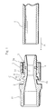
- Figure 1 is a cross-sectional view showing a preferred embodiment of a pipe joint C
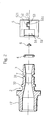
- Figure 2 is an exploded view
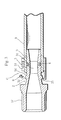
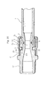
- Figure 3 is a cross-sectional view of a state in which a pipe is connected.
- mark 1 indicates a water-supplying pipe to be connected composed of, for example, synthetic resin such as crosslinked-polyethylene, polybutene, etc.
- Mark 2 indicates a joint main body having an insertion cylinder portion 3 to be inserted to an end portion of the pipe 1 on one end side.
- a hitching stop portion 31 having a plural-staged peripheral taper for hitching the pipe 1 to stop, is formed on periphery of the insertion cylinder portion 3.
- a male screw 17 screwing to a connected member is formed on another end side (end portion) of the joint main body.
- Mark 4 indicates an 0-ring (sealing member) attached to a peripheral concave groove 7 on the insertion cylinder portion 3 of the joint main body 2.
- Mark 5 indicates a clamp ring composed of spring steel having a split (slit) 51 in an axis direction for fastening the end portion of the pipe 1 outserted to the insertion cylinder 3 with elastic fastening force.
- Mark 6 indicates a diameter-extension piece composed of steel of high rigidity which is detachably press-fitted to the slit 51 resisting the elastic force of the clamp ring 5 to extend the clamp ring 5 as the pipe 1 can be inserted to the clamp ring 5 in an initial state shown in Figure 1.
- the slit 51 is formed by a protruding portion 521 formed on an end face 52 and a concave portion 531 formed on another end face 53 fitting each other.
- inner end edges of the both end faces 52 and 53 facing on the both sides of the slit 51 are formed in R-shaped chamfers.
- Radius of curvature R of the inner end edge, set corresponding to diameter, wall thickness, material, etc. of the pipe 1, is preferably set to be approximately 0.4mm to 0.6mm in a case that outer diameter of the clamp ring 5 in the free state is ⁇ 15mm to 35mm. Therefore, with the inner end edges of the both end faces 52 and 53 formed in R-shaped chamfers, surface of the pipe 1 is not damaged when the clamp ring 5 contracts, the diameter-extension piece 6 is smoothly detached, and strong fastening force works on the pipe 1.
- one end side (an inner end side of the slit 51) is notched in rectangle to form a notched portion 54, and detachment of the diameter-extension piece 6 becomes possible thereby (refer to Figure 3).
- an inward flange 55 is formed on a periphery of the clamp ring 5 except the notched portion 54.
- the inward flange 55 is hitched to a hitching flange 32 formed on the joint main body 2 to stop the clamp ring 5 extended by the diameter-extension piece 6 (refer to Figure 1).
- a knurling or tapered hitching stop face for hitching onto the peripheral face of the pipe 1 may be formed on an inner peripheral face of the clamp ring 5.
- the diameter-extension piece 6 is composed of a press-fit portion 61 press-fitted to the slit 51 and a regulation portion 62 which contacts a side end face of the clamp ring 5 to regulate press-fit position of the diameter-extension piece 6 unitedly formed. And, pressed surfaces 611, held by the slit 51 of the clamp ring 5, are formed on both sides of the press-fit portion 61 on the peripheral side (when press-fitted).
- a protruding contact portion 63 which contacts the forth end portion of the inserted pipe 1 is formed on the inner peripheral side (when press-fitted) of the diameter-extension piece 6, and a concave portion 64, allowing intrusion of the forth end portion of the pipe 1 when the diameter-extension piece 6 turns as described later, is formed on a central portion of the diameter-extension piece 6.
- an extended portion 621 is formed by extending the peripheral side (when press-fitted) of the regulation portion 62 slightly outward from the press-fit portion 61.
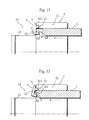
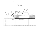
- a predetermined interval r is set between an end portion S on the peripheral side of the extended portion 621 of the regulation portion 62 and a contact portion P on the protruding contact portion 63 which contacts the forth end portion of the pipe 1 as sufficient angular moment works on the press-fitted diameter-extension piece 6 to facilitate the detachment of the diameter-extension piece 6 from the slit 51.
- the end portion S on the peripheral side of the regulation portion 62 is a center of turning of the diameter-extension piece 6 in the detachment (refer to Figure 12 and Figure 13).
- the pipe 1 is stopped onto the joint main body 2 because the pipe 1 is contracted by the clamp ring 5 and bites into the insertion cylinder portion 3, and tightness is kept on the entire inner periphery of the pipe 1 by the sealing member 4 without interruption. Therefore, excellent leakage prevention is always kept and durable and stable sealing ability is secured even with variation of diameter of the pipe 1 and dimensional change caused by thermal deformation.
- the connecting work comprising only pushing the pipe 1 to the joint main body 2, can be completed very efficiently with one movement and without connecting tools, fastening parts, and high skill. And, workability at working sites is remarkably improved because the completion of the connecting work is checked by the detachment sound of the diameter-extension piece 6. And, control of the parts is easy, preparation of the parts at the working sites is easy and certain, and missing of the parts hardly occurs because the parts of the pipe joint are unitedly assembled beforehand.
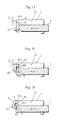
- Figure 14 shows a different example of the diameter-extension piece 6.
- the concave portion receiving the forth end portion of the pipe 1 is not formed on the press-fit portion 61.
- the interval r between the end portion S on the extended portion 621 of the regulation portion 62 and the contact portion P on the pipe 1 is made considerably small.
- the pushing force of the pipe 1 may be rather stronger than that of the embodiment shown in Figure 11 through Figure 13.
- Figure 15 and Figure 16 show another example of the diameter-extension piece 6.
- the interval r between the end portion S on the extended portion 621 of the regulation portion 62 and the contact portion P on the pipe 1 is made slightly small because the extended portion 621 is not formed on the regulation portion 62.
- the certain detachment of the diameter-extension piece 6 is achieved by insertion of the pipe 1 with this construction, the pushing force of the pipe 1 may be rather stronger than that of the embodiment shown in Figure 11 through Figure 13.
- Figure 17 through Figure 22 show another embodiment of the pipe joint C.
- a cover 14 covering the clamp ring 5 is provided.
- a female screw 141 formed on an inner face of a base portion of the cover 14 screws to a male screw 19 formed on an outer face of the insertion cylinder portion 3 of the joint main body 2 near a base portion of the insertion cylinder portion 3, and an escape space 16 of ring for storing the diameter-extension piece 6 detached from the slit 51 of the clamp ring 5 is formed between the cover 14 and the insertion cylinder portion 3.
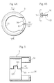
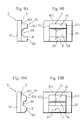
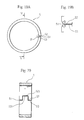
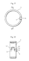
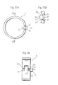
- the clamp ring 5 as shown in a side view of Figure 19A, an enlarged view (of a part within an imaginary circle in Figure 19A) of a principal portion of Figure 19B, and Figure 20 showing a free state of the clamp ring 5 and in Figure 21 and Figure 22 showing an extended state of the clamp ring 5, has a very simple construction in which only a concavo-convex slit 51 is provided without forming the notched portion 54 and the inward flange 55 provided to the clamp ring 5 of the former-described embodiment.
- the cover 14 which protects the connected portion of the pipe 1.
- the cover 14 is preferably composed of transparent resin such as PA (polyamide, nylon), PES (polyethersulphone), or PC (polycarbonate) to check the detachment of the diameter-extension piece 6 (visually) from the outside.
- Figures 23 through 29 show still another embodiment of the pipe joint C.
- a bent portion 612 is disposed on an end portion of a press-fit portion 61 of a diameter-extension piece 6, and a regulation portion 62 is continuous from the bent portion 612.
- the press-fit portion 61 is formed by bending a side portion of a rectangle flat plate
- the regulation portion 62 is a rectangle flat plate wider than the press-fit portion 61 one of which side faces is tapered
- the press-fit portion 61 and the regulation portion 62 are continuous. That is to say, the diameter-extension piece 6 has a configuration of an approximately T-shaped flat plate bent at a middle portion.
- middle portions of pressed surfaces 611 of the press-fit portion 61 are held by inner end edges of both end faces 52 and 53 of the clamp ring 5, the press-fit portion 61 is protruded inward in the diameter direction of the clamp ring 5 as to contact a forth end face of an inserted pipe 1, and the regulation portion 62 is protruded outward in the axis direction of the clamp ring 5 as to position the tapered side as a forth end.
- the clamp ring 5 and the diameter-extension piece 6 assembled as described above are fit into a cover 14.
- Plural (three, for example) contact portions 15 are formed in a peripheral direction on an inner peripheral face of the cover 14 to regulate the clamp ring 5 not to excessively move to inner side in the axis direction of the pipe joint by touching an end face of the clamp ring 5.
- the diameter-extension piece 6 (the regulation portion 62) is prevented from being caught by a gap between the contact portion 15 and the end face of the clamp ring 5 when the clamp ring 5 is fitted inside the cover 14 because the diameter-extension piece 6 is disposed as to protrude the regulation portion 62 (for longer than the minute distance) from the end face of the clamp ring 5. Therefore, the diameter-extension piece 6 is certainly detached from the clamp ring 5.
- the press-fit portion 61 does not stick to the forth end face of the pipe 1 even if the pipe 1 is made of soft resin because the forth end face of the pipe 1 pushes the flat press-fit portion 61.
- the diameter-extension piece 6 can keep a stable held position against forces of peripheral direction because the press-fit portion 61 is held by the inner end edges of the clamp ring 5 as shown in Figure 27B. Therefore, the diameter-extension piece 6 is not detached from the clamp ring 5 even if the pipe 1 is inserted with rotation as to be screwed.
- angular moment of the diameter-extension piece 6 can be increased by transfering the center (supporting point) of turning of the diameter-extension piece 6 from the outer end portion S to the contact point n, and the diameter-extension piece 6 can be certainly detached by small force.
- the diameter-extension piece 6 shown in Figure 25 may be used for the pipe joint without the cover as shown in Figure 1.
- design of the pipe joint may be modified within the scope of the invention.
- the pipe joint of the present invention by only one pushing movement of the pipe 1, the diameter-extension piece 6 is detached from the slit 51 of the clamp ring 5, the clamp ring 5 contracts and fastens the end portion of the pipe 1, the inner face of the pipe 1 fits to the sealing member 4 to tightly seal the joint, and the connecting work is completed.
- the connecting work comprising only pushing the pipe 1 to the joint main body 2
- control of the parts is easy, preparation of the parts at the working sites is easy and certain, and missing of the parts hardly occurs because the parts of the pipe joint are unitedly assembled beforehand.
- the position of the press fitting can be easily and certainly regulated by the regulation portion 62 and the press-fitted state becomes stable.
- the diameter-extension piece 6 is easily turned and certainly detached from the slit 51 by the contact of the pipe 1 with the protruding contact portion 63 of the diameter-extension piece 6.
- the diameter-extension piece 6 is (unitedly) easily made to reduce the production cost and time.
- the press-fit portion 61 is pushed by the forth end portion of the pipe 1
- the regulation portion 62 is oscillated (outward in the diameter direction) to contact a predetermined portion of the pipe joint, and the diameter-extension piece 6 can be detached with smaller force thereby.
- the diameter-extension piece 6 can keep a stable held position against forces of peripheral direction because the press-fit portion 61 is held by the inner end edges of the clamp ring 5. Therefore, the diameter-extension piece 6 is not detached from the clamp ring 5 even if the pipe 1 is inserted with rotation as to be screwed.
- the detachment of the diameter-extension piece 6 is made easy by the large angular moment added to the diameter-extension piece 6 with small pushing force of the pipe 1 by the appropriate interval r set between the end portion S on the peripheral side as the center of the turn and the portion (contact portion) P which contacts the forth end portion of the pipe 1.
- the fastening force works on the pipe 1 in the peripheral direction without interruption because the slit 51 is formed as to be concavo-convex, and the sealability is improved thereby.
- the detachment of the diameter-extension piece 6 can be easily (visually) recognized for the cover 14 composed of transparent resin and the pipe 1 is certainly connected.
Landscapes
- Engineering & Computer Science (AREA)
- General Engineering & Computer Science (AREA)
- Mechanical Engineering (AREA)
- Quick-Acting Or Multi-Walled Pipe Joints (AREA)
- Joints With Sleeves (AREA)
- Joints That Cut Off Fluids, And Hose Joints (AREA)
- Branch Pipes, Bends, And The Like (AREA)
Abstract
Description
Claims (12)
- A pipe joint comprising a joint main body (2) having an insertion cylinder portion (3) inserted to an end portion of a pipe (1) to be connected, a sealing member (4) attached to a peripheral concave groove (7) on the insertion cylinder portion (3), a clamp ring (5) with a slit (51) for fastening the end portion of the pipe (1) outserted to the insertion cylinder portion (3) with elastic fastening force, and a diameter-extension piece (6) detachably held by end faces of the slit (51) as to extend the clamp ring (5) resisting the elastic force of the clamp ring (5) and detached by a forth end portion of the pipe (1) which contacts the diameter-extension piece (6).
- The pipe joint as set forth in claim 1, wherein an escape space (16) for storing the diameter-extension piece (6) detached from the clamp ring (5) by the contact with the forth end of the inserted pipe(1) is formed in the joint main body (2).
- The pipe joint as set forth in claim 1 or claim 2, wherein the diameter-extension piece (6) is composed of a press-fit portion (61) held by the slit (51) and a regulation portion (62) which contacts a side end face of the clamp ring (5) to regulate press-fit position of the diameter-extension piece (6) unitedly formed.
- The pipe joint as set forth in claim 3, wherein a protruding contact portion (63) which contacts the forth end portion of the pipe(1) is formed on the press-fit portion (61) of the diameter-extension piece (6).
- The pipe joint as set forth in claim 3, wherein a bent portion (612) is formed on an end portion of the press-fit portion (61) and a regulation portion (62) is continuously formed with the bent portion (612).
- The pipe joint as set forth in claim 5, wherein the press-fit portion (61) is held by inner end edges of the clamp ring (5), an end side of the diameter-extension piece (6) is protruded inward in a diameter direction of the clamp ring (5), and the regulation portion (62) is protruded outward in an axis direction of the clamp ring (5) in a state that the diameter-extension piece (6) is press-fitted to the clamp ring (5).
- The pipe joint as set forth in claim 1 or claim 2, wherein a predetermined interval (r) for facilitating the detachment of the diameter-extension piece (6) is set between an end portion (s) on the peripheral side of the regulation portion (62) and a portion (p) which contacts the forth end portion of the pipe (1) in a state that the diameter-extension piece (6) is press-fitted to the clamp ring (5).
- The pipe joint as set forth in claim 1 or claim 2, wherein inner end edges of both end faces (52, 53) facing on the both sides of the slit (51) are formed in R-shaped chamfers.
- The pipe joint as set forth in claim 8, wherein a protruding portion (521) formed on the end face (52) engages with a concave portion (531) formed on the end face (53).
- The pipe joint as set forth in claim 1 or claim 2, wherein detachment sound can be recognized from the outside is generated when the diameter-extension piece (6) is detached from the slit (51) by the inserted pipe (1).
- The pipe joint as set forth in claim 1 or claim 2, wherein a cover (14) for covering the clamp ring (5) is attached to the joint main body (2).
- The pipe joint as set forth in claim 11, wherein the cover (14) is composed of transparent resin.
Applications Claiming Priority (4)
| Application Number | Priority Date | Filing Date | Title |
|---|---|---|---|
| JP2000028725 | 2000-02-07 | ||
| JP2000028725 | 2000-02-07 | ||
| JP2000210389 | 2000-07-11 | ||
| JP2000210389A JP3405966B2 (en) | 2000-02-07 | 2000-07-11 | Pipe fitting |
Publications (3)
| Publication Number | Publication Date |
|---|---|
| EP1122485A2 true EP1122485A2 (en) | 2001-08-08 |
| EP1122485A3 EP1122485A3 (en) | 2003-01-08 |
| EP1122485B1 EP1122485B1 (en) | 2005-02-23 |
Family
ID=26584945
Family Applications (1)
| Application Number | Title | Priority Date | Filing Date |
|---|---|---|---|
| EP00122230A Expired - Lifetime EP1122485B1 (en) | 2000-02-07 | 2000-10-17 | Pipe joint |
Country Status (11)
| Country | Link |
|---|---|
| US (2) | US6443500B1 (en) |
| EP (1) | EP1122485B1 (en) |
| JP (1) | JP3405966B2 (en) |
| KR (1) | KR100394908B1 (en) |
| CN (1) | CN1126896C (en) |
| CA (1) | CA2319921C (en) |
| DE (1) | DE60018259T2 (en) |
| ES (1) | ES2234498T3 (en) |
| HK (1) | HK1039170B (en) |
| SG (1) | SG90180A1 (en) |
| TW (1) | TW509767B (en) |
Cited By (8)
| Publication number | Priority date | Publication date | Assignee | Title |
|---|---|---|---|---|
| GB2408084A (en) * | 2003-10-23 | 2005-05-18 | Mark John Curtis | Push fit pipe joint uses insert to retain pipe |
| WO2006094361A1 (en) * | 2005-03-11 | 2006-09-14 | Vinidex Pty Limited | Socketing of pipe |
| WO2008148728A1 (en) | 2007-06-02 | 2008-12-11 | Uponor Innovation Ab | Clamping fitting for a pipe |
| EP1837581A3 (en) * | 2006-03-20 | 2010-01-20 | R. Nussbaum AG | Connecting piece |
| EP1662190A3 (en) * | 2004-11-29 | 2010-02-17 | Higashio Mech Co., Ltd. | Pipe joint |
| EP2669563A1 (en) | 2012-06-01 | 2013-12-04 | Uponor Innovation AB | Pipe connector |
| EP2505897B1 (en) * | 2011-03-29 | 2016-08-03 | IPA Produktions- und Vertriebsges.m.b.H. | Crimp connection for plastic tubes |
| DE202017006479U1 (en) | 2017-12-18 | 2019-03-19 | Rehau Pty Ltd | pipe connection |
Families Citing this family (65)
| Publication number | Priority date | Publication date | Assignee | Title |
|---|---|---|---|---|
| US6733525B2 (en) * | 2001-03-23 | 2004-05-11 | Edwards Lifesciences Corporation | Rolled minimally-invasive heart valves and methods of use |
| JP3843288B2 (en) * | 2002-04-19 | 2006-11-08 | 井上スダレ株式会社 | Pipe fitting |
| JP4121299B2 (en) * | 2002-04-22 | 2008-07-23 | 株式会社オンダ製作所 | Fitting |
| US7014218B2 (en) * | 2003-04-17 | 2006-03-21 | Parker-Hannifin | Universal fitting nipple |
| JP4567350B2 (en) * | 2004-03-02 | 2010-10-20 | 株式会社ベンカン・ジャパン | Pipe fitting |
| US7131671B2 (en) * | 2005-01-07 | 2006-11-07 | Saarem Myrl J | Transparent coupling |
| JP2006283865A (en) * | 2005-03-31 | 2006-10-19 | Sekisui Chem Co Ltd | Pipe fitting |
| US7448653B2 (en) | 2005-06-10 | 2008-11-11 | Value Plastics, Inc. | Female connector for releasable coupling with a male connector defining a fluid conduit |
| US7806139B2 (en) | 2006-01-20 | 2010-10-05 | Value Plastics, Inc. | Fluid conduit coupling assembly having male and female couplers with integral valves |
| KR100597337B1 (en) | 2006-01-26 | 2006-07-06 | 주식회사 하이트롤 | Cavitation Venturi for Auxiliary Water Supply Systems in Reactors |
| US20090026758A1 (en) * | 2007-07-24 | 2009-01-29 | Sanzone Brian D | Tube fitting with indication of fit |
| USD654573S1 (en) | 2007-11-19 | 2012-02-21 | Value Plastics, Inc. | Female quick connect fitting |
| US8235426B2 (en) | 2008-07-03 | 2012-08-07 | Nordson Corporation | Latch assembly for joining two conduits |
| AT507565B1 (en) * | 2009-04-28 | 2010-06-15 | Ke Kelit Kunststoffwerk Gmbh | CONNECTION DEVICE FOR A PLASTIC TUBE ON A CONNECTION NIPPLE |
| US20100314869A1 (en) * | 2009-06-11 | 2010-12-16 | Wen-Pin Kuo | Pipe connector |
| USD655393S1 (en) | 2009-06-23 | 2012-03-06 | Value Plastics, Inc. | Multi-port valve |
| JP2011102606A (en) * | 2009-11-10 | 2011-05-26 | Toyox Co Ltd | Hose connector |
| USD783815S1 (en) | 2009-12-09 | 2017-04-11 | General Electric Company | Male dual lumen bayonet connector |
| US10711930B2 (en) | 2009-12-09 | 2020-07-14 | Nordson Corporation | Releasable connection assembly |
| US9388929B2 (en) | 2009-12-09 | 2016-07-12 | Nordson Corporation | Male bayonet connector |
| USD650478S1 (en) | 2009-12-23 | 2011-12-13 | Value Plastics, Inc. | Female dual lumen connector |
| USD649240S1 (en) | 2009-12-09 | 2011-11-22 | Value Plastics, Inc. | Male dual lumen bayonet connector |
| US9440250B2 (en) | 2009-12-18 | 2016-09-13 | Rain Bird Corporation | Pop-up irrigation device for use with low-pressure irrigation systems |
| US8950789B2 (en) | 2009-12-18 | 2015-02-10 | Rain Bird Corporation | Barbed connection for use with irrigation tubing |
| SG181932A1 (en) | 2009-12-23 | 2012-07-30 | Nordson Corp | Button latch with integrally molded cantilever springs |
| JP5714028B2 (en) | 2009-12-23 | 2015-05-07 | ノードソン コーポレーションNordson Corporation | Fluid connector latch with profile retraction |
| EP2603725B1 (en) * | 2010-08-10 | 2017-03-22 | Netafim Ltd. | Fitting assembly |
| USD652511S1 (en) | 2011-02-11 | 2012-01-17 | Value Plastics, Inc. | Female body of connector for fluid tubing |
| USD652510S1 (en) | 2011-02-11 | 2012-01-17 | Value Plastics, Inc. | Connector for fluid tubing |
| USD663022S1 (en) | 2011-02-11 | 2012-07-03 | Nordson Corporation | Male body of connector for fluid tubing |
| JP5736202B2 (en) * | 2011-03-22 | 2015-06-17 | 井上スダレ株式会社 | Pipe fitting |
| JP4906973B1 (en) * | 2011-03-22 | 2012-03-28 | 井上スダレ株式会社 | Pipe fitting |
| ES2630020T3 (en) * | 2011-03-28 | 2017-08-17 | Flexin Group S.R.L. | Flexible hose connector |
| US8898876B2 (en) | 2011-03-30 | 2014-12-02 | Rain Bird Corporation | Barbed fittings, fitting insertion tools and methods relating to same |
| JP2012219942A (en) * | 2011-04-11 | 2012-11-12 | Mitsubishi Plastics Inc | Joint for piping and joint structure |
| JP2013029170A (en) * | 2011-07-28 | 2013-02-07 | Nifco Inc | Tube holder |
| USD699840S1 (en) | 2011-07-29 | 2014-02-18 | Nordson Corporation | Male body of connector for fluid tubing |
| USD698440S1 (en) | 2011-07-29 | 2014-01-28 | Nordson Corporation | Connector for fluid tubing |
| USD699841S1 (en) | 2011-07-29 | 2014-02-18 | Nordson Corporation | Female body of connector for fluid tubing |
| JP5890166B2 (en) * | 2011-12-16 | 2016-03-22 | 株式会社ブリヂストン | Pipe fitting and locking member |
| USD709612S1 (en) | 2011-12-23 | 2014-07-22 | Nordson Corporation | Female dual lumen connector |
| CH706036A1 (en) * | 2012-01-23 | 2013-07-31 | Brugg Rohr Ag Holding | Method for connecting a connection piece with a heat-insulated conduit. |
| PT2677224T (en) * | 2012-06-20 | 2016-07-15 | Fischer Georg Jrg Ag | Clamp connection for pipes |
| AU2014236478B2 (en) * | 2013-03-14 | 2018-11-22 | Connector Subsea Solutions (UK) Ltd | Pipe end seal assembly |
| US9664321B2 (en) | 2013-05-20 | 2017-05-30 | Steere Enterprises, Inc. | Clean air duct and retaining clip and assembly thereof |
| US10859194B2 (en) | 2013-05-20 | 2020-12-08 | Steere Enterprises, Inc. | Clean air duct and retaining clip and assembly thereof |
| CN103307377B (en) * | 2013-06-07 | 2016-01-13 | 湖州师范学院 | A kind of health soft wood sealing diversion plug with cavity |
| CN103486373A (en) * | 2013-10-09 | 2014-01-01 | 佛山市日丰企业有限公司 | Push type rapidly-connected pipe fitting |
| GB2535688B (en) * | 2015-01-07 | 2020-12-09 | Stats Uk Ltd | Pipe isolation & intervention |
| CN104847346A (en) * | 2015-05-27 | 2015-08-19 | 西安科技大学 | Coal spontaneous combustion gas marker acquiring device for goaf |
| USD838366S1 (en) | 2016-10-31 | 2019-01-15 | Nordson Corporation | Blood pressure connector |
| CN107366790A (en) * | 2017-08-18 | 2017-11-21 | 玉环县玉立水暖器材厂 | A kind of New-type pipe joint |
| WO2019209860A1 (en) * | 2018-04-24 | 2019-10-31 | Reliance Worldwide Corporation | Fluid connector |
| CA3096665A1 (en) | 2018-08-14 | 2020-02-20 | Reliance Worldwide Corporation | Tubular connector |
| US12338928B2 (en) | 2018-08-14 | 2025-06-24 | Reliance Worldwide Corporation | Plumbing fitting |
| US12553555B2 (en) | 2018-08-14 | 2026-02-17 | Reliance Worldwide Corporation | Device and method for assembling components of a plumbing fitting |
| US12345361B2 (en) | 2018-08-14 | 2025-07-01 | Reliance Worldwide Corporation | Plumbing fitting |
| US20210088164A1 (en) * | 2019-09-19 | 2021-03-25 | Sidus Technologies, Inc. | Push connector with connection confirmation feedback |
| US10781948B1 (en) | 2019-11-04 | 2020-09-22 | Trinity Bay Equipment Holdings, LLC | Pipe connector with annular communication |
| JP7449106B2 (en) * | 2020-01-31 | 2024-03-13 | 株式会社イノアック住環境 | Hose fixing structure |
| CN112038998B (en) * | 2020-08-25 | 2022-05-06 | 安徽送变电工程有限公司 | Snap-fit cable hanger |
| CN113864560B (en) * | 2021-08-18 | 2023-10-24 | 韦玉婷 | PVC compressive corrugated pipe |
| CN115596915A (en) * | 2022-11-08 | 2023-01-13 | 河北世昌汽车部件股份有限公司(Cn) | Quick Connector |
| JP2024168782A (en) * | 2023-05-24 | 2024-12-05 | 豊田合成株式会社 | Connector Structure |
| CN116697161A (en) * | 2023-05-31 | 2023-09-05 | 华能伊敏煤电有限责任公司 | Oil pipe joint and intelligent vehicle steering system |
Family Cites Families (15)
| Publication number | Priority date | Publication date | Assignee | Title |
|---|---|---|---|---|
| US3885819A (en) * | 1972-11-21 | 1975-05-27 | Herbert Egerer | Compressed air hose connection |
| US4226445A (en) * | 1978-10-20 | 1980-10-07 | Armaturenfabrik Hermann Voss Gmbh & Co. | Hose and pipe coupling |
| US4278279A (en) * | 1979-06-07 | 1981-07-14 | Zimmerman Harry M | Cam-lock fitting |
| US4635966A (en) * | 1985-09-20 | 1987-01-13 | Chrysler Motors Corporation | Hose connector |
| DE3911406A1 (en) * | 1989-04-07 | 1990-10-11 | Kirchner Fraenk Rohr | Two-part metallic clamping connector for pipes and hoses consisting of a polymeric material |
| US5022687A (en) * | 1989-09-18 | 1991-06-11 | Yokohama Aeroquip Corporation | Pipe coupling |
| DE3936102C1 (en) * | 1989-10-30 | 1991-01-17 | Karl Dipl.-Ing. 4040 Neuss De Weinhold | |
| JP2779866B2 (en) * | 1990-03-23 | 1998-07-23 | ニッタ・ムアー株式会社 | Pipe fittings |
| JPH05231571A (en) * | 1992-02-17 | 1993-09-07 | Sekisui Chem Co Ltd | Tube joint |
| DE9307361U1 (en) * | 1993-05-14 | 1993-07-15 | Armaturenfabrik Hermann Voss GmbH + Co, 5272 Wipperfürth | Connection device for pipes with slotted clamp ring |
| US5558375A (en) * | 1995-07-10 | 1996-09-24 | Deere & Company | Quick attach, reusable hose fittings |
| DE19542463B4 (en) * | 1995-11-15 | 2004-05-27 | J. Van Walraven B.V. | pipe coupling |
| BR9601539A (en) * | 1996-04-12 | 2004-06-29 | Tampas Click Ltda | Mounting and connecting indicator for fuel or general fluid lines |
| DE19638029C2 (en) * | 1996-09-18 | 2000-08-03 | Fischer Georg Automobilguss | Pipe connection with clamping ring |
| DE19707371A1 (en) * | 1997-02-25 | 1998-08-27 | Voss Armaturen | Pressure fluid plug-in coupling |
-
2000
- 2000-07-11 JP JP2000210389A patent/JP3405966B2/en not_active Expired - Lifetime
- 2000-09-14 US US09/662,313 patent/US6443500B1/en not_active Expired - Lifetime
- 2000-09-18 CA CA002319921A patent/CA2319921C/en not_active Expired - Lifetime
- 2000-10-02 KR KR10-2000-0057793A patent/KR100394908B1/en not_active Expired - Fee Related
- 2000-10-09 TW TW089121269A patent/TW509767B/en not_active IP Right Cessation
- 2000-10-12 SG SG200005885A patent/SG90180A1/en unknown
- 2000-10-17 DE DE60018259T patent/DE60018259T2/en not_active Expired - Lifetime
- 2000-10-17 EP EP00122230A patent/EP1122485B1/en not_active Expired - Lifetime
- 2000-10-17 ES ES00122230T patent/ES2234498T3/en not_active Expired - Lifetime
- 2000-11-15 CN CN00132958A patent/CN1126896C/en not_active Expired - Lifetime
-
2002
- 2002-01-23 HK HK02100526.1A patent/HK1039170B/en not_active IP Right Cessation
- 2002-07-24 US US10/201,257 patent/US6726253B2/en not_active Expired - Lifetime
Cited By (11)
| Publication number | Priority date | Publication date | Assignee | Title |
|---|---|---|---|---|
| GB2408084A (en) * | 2003-10-23 | 2005-05-18 | Mark John Curtis | Push fit pipe joint uses insert to retain pipe |
| GB2408084B (en) * | 2003-10-23 | 2006-11-08 | Mark John Curtis | Push fit pipe joint |
| EP1662190A3 (en) * | 2004-11-29 | 2010-02-17 | Higashio Mech Co., Ltd. | Pipe joint |
| WO2006094361A1 (en) * | 2005-03-11 | 2006-09-14 | Vinidex Pty Limited | Socketing of pipe |
| US7776248B2 (en) | 2005-03-11 | 2010-08-17 | Vinidex Pty Limited | Socketing of pipe |
| EP1837581A3 (en) * | 2006-03-20 | 2010-01-20 | R. Nussbaum AG | Connecting piece |
| WO2008148728A1 (en) | 2007-06-02 | 2008-12-11 | Uponor Innovation Ab | Clamping fitting for a pipe |
| US8226127B2 (en) | 2007-06-02 | 2012-07-24 | Uponor Innovation Ab | Clamp fitting for a pipe |
| EP2505897B1 (en) * | 2011-03-29 | 2016-08-03 | IPA Produktions- und Vertriebsges.m.b.H. | Crimp connection for plastic tubes |
| EP2669563A1 (en) | 2012-06-01 | 2013-12-04 | Uponor Innovation AB | Pipe connector |
| DE202017006479U1 (en) | 2017-12-18 | 2019-03-19 | Rehau Pty Ltd | pipe connection |
Also Published As
| Publication number | Publication date |
|---|---|
| DE60018259T2 (en) | 2006-02-16 |
| JP2001295974A (en) | 2001-10-26 |
| US6726253B2 (en) | 2004-04-27 |
| TW509767B (en) | 2002-11-11 |
| CA2319921C (en) | 2007-01-16 |
| KR100394908B1 (en) | 2003-08-19 |
| CA2319921A1 (en) | 2001-08-07 |
| HK1039170A1 (en) | 2002-04-12 |
| KR20010077888A (en) | 2001-08-20 |
| EP1122485A3 (en) | 2003-01-08 |
| US6443500B1 (en) | 2002-09-03 |
| US20020185861A1 (en) | 2002-12-12 |
| DE60018259D1 (en) | 2005-03-31 |
| EP1122485B1 (en) | 2005-02-23 |
| HK1039170B (en) | 2005-07-15 |
| SG90180A1 (en) | 2002-07-23 |
| JP3405966B2 (en) | 2003-05-12 |
| CN1308198A (en) | 2001-08-15 |
| ES2234498T3 (en) | 2005-07-01 |
| CN1126896C (en) | 2003-11-05 |
Similar Documents
| Publication | Publication Date | Title |
|---|---|---|
| EP1122485B1 (en) | Pipe joint | |
| KR100392500B1 (en) | Tube Joint | |
| US5979910A (en) | Retainer for use in fluid couplings | |
| KR100397312B1 (en) | Pipe connector | |
| EP0779957B1 (en) | Pipe joining construction | |
| JP2008025615A (en) | Pipe fitting | |
| US20100187811A1 (en) | Rotatable coupling | |
| US20190024831A1 (en) | Connector for fluidic connection between two hoses or the like and arrangement associated | |
| JP4034433B2 (en) | Tube connection structure | |
| JP2986522B2 (en) | Flexible pipe fittings | |
| JP2024042598A (en) | Hose fitting with cap nut | |
| JPS6313813Y2 (en) | ||
| JP2000310376A (en) | Connection device between flexible pipe and joint | |
| JP2011007267A (en) | Pipe joint with hose retaining mechanism | |
| RU2344332C2 (en) | Structure for connection of pipes | |
| KR100530660B1 (en) | pipejoint | |
| JPH0624288U (en) | Pipe fitting | |
| JPH0710155Y2 (en) | Coupling device for piping | |
| KR20120060155A (en) | Pipe connection structure | |
| JP4338886B2 (en) | Segment positioning structure | |
| JP3834756B2 (en) | Pipe fitting | |
| JP2013204737A (en) | Pipe end corrosion-proof structure in pipe joint | |
| KR20240069216A (en) | connector for pipe | |
| JP3133254B2 (en) | Plastic fittings for fume pipes | |
| JPH083823Y2 (en) | Rust-proof structure at the end of flexible joints |
Legal Events
| Date | Code | Title | Description |
|---|---|---|---|
| PUAI | Public reference made under article 153(3) epc to a published international application that has entered the european phase |
Free format text: ORIGINAL CODE: 0009012 |
|
| AK | Designated contracting states |
Kind code of ref document: A2 Designated state(s): AT BE CH CY DE DK ES FI FR GB GR IE IT LI LU MC NL PT SE |
|
| AX | Request for extension of the european patent |
Free format text: AL;LT;LV;MK;RO;SI |
|
| PUAL | Search report despatched |
Free format text: ORIGINAL CODE: 0009013 |
|
| AK | Designated contracting states |
Kind code of ref document: A3 Designated state(s): AT BE CH CY DE DK ES FI FR GB GR IE IT LI LU MC NL PT SE |
|
| AX | Request for extension of the european patent |
Free format text: AL;LT;LV;MK;RO;SI |
|
| 17P | Request for examination filed |
Effective date: 20030604 |
|
| AKX | Designation fees paid |
Designated state(s): DE ES FR GB IT NL |
|
| 17Q | First examination report despatched |
Effective date: 20030828 |
|
| GRAP | Despatch of communication of intention to grant a patent |
Free format text: ORIGINAL CODE: EPIDOSNIGR1 |
|
| GRAS | Grant fee paid |
Free format text: ORIGINAL CODE: EPIDOSNIGR3 |
|
| GRAA | (expected) grant |
Free format text: ORIGINAL CODE: 0009210 |
|
| AK | Designated contracting states |
Kind code of ref document: B1 Designated state(s): DE ES FR GB IT NL |
|
| REG | Reference to a national code |
Ref country code: GB Ref legal event code: FG4D |
|
| REG | Reference to a national code |
Ref country code: IE Ref legal event code: FG4D |
|
| REF | Corresponds to: |
Ref document number: 60018259 Country of ref document: DE Date of ref document: 20050331 Kind code of ref document: P |
|
| REG | Reference to a national code |
Ref country code: ES Ref legal event code: FG2A Ref document number: 2234498 Country of ref document: ES Kind code of ref document: T3 |
|
| REG | Reference to a national code |
Ref country code: HK Ref legal event code: GR Ref document number: 1039170 Country of ref document: HK |
|
| REG | Reference to a national code |
Ref country code: GB Ref legal event code: 732E |
|
| ET | Fr: translation filed | ||
| PLBE | No opposition filed within time limit |
Free format text: ORIGINAL CODE: 0009261 |
|
| STAA | Information on the status of an ep patent application or granted ep patent |
Free format text: STATUS: NO OPPOSITION FILED WITHIN TIME LIMIT |
|
| NLS | Nl: assignments of ep-patents |
Owner name: SEKISUI CHEMICAL CO., LTD. Effective date: 20051109 Owner name: INOUE SUDARE CO., LTD. Effective date: 20051109 Owner name: HIGASHIO MECH CO., LTD. Effective date: 20051109 |
|
| REG | Reference to a national code |
Ref country code: ES Ref legal event code: PC2A |
|
| 26N | No opposition filed |
Effective date: 20051124 |
|
| REG | Reference to a national code |
Ref country code: FR Ref legal event code: TP |
|
| REG | Reference to a national code |
Ref country code: FR Ref legal event code: PLFP Year of fee payment: 16 |
|
| REG | Reference to a national code |
Ref country code: FR Ref legal event code: PLFP Year of fee payment: 17 |
|
| REG | Reference to a national code |
Ref country code: FR Ref legal event code: PLFP Year of fee payment: 18 |
|
| REG | Reference to a national code |
Ref country code: FR Ref legal event code: PLFP Year of fee payment: 19 |
|
| PGFP | Annual fee paid to national office [announced via postgrant information from national office to epo] |
Ref country code: DE Payment date: 20191024 Year of fee payment: 20 Ref country code: NL Payment date: 20191016 Year of fee payment: 20 |
|
| PGFP | Annual fee paid to national office [announced via postgrant information from national office to epo] |
Ref country code: FR Payment date: 20191028 Year of fee payment: 20 Ref country code: ES Payment date: 20191105 Year of fee payment: 20 Ref country code: IT Payment date: 20191025 Year of fee payment: 20 |
|
| PGFP | Annual fee paid to national office [announced via postgrant information from national office to epo] |
Ref country code: GB Payment date: 20191018 Year of fee payment: 20 |
|
| REG | Reference to a national code |
Ref country code: DE Ref legal event code: R071 Ref document number: 60018259 Country of ref document: DE |
|
| REG | Reference to a national code |
Ref country code: NL Ref legal event code: MK Effective date: 20201016 |
|
| REG | Reference to a national code |
Ref country code: GB Ref legal event code: PE20 Expiry date: 20201016 |
|
| PG25 | Lapsed in a contracting state [announced via postgrant information from national office to epo] |
Ref country code: GB Free format text: LAPSE BECAUSE OF EXPIRATION OF PROTECTION Effective date: 20201016 |
|
| REG | Reference to a national code |
Ref country code: ES Ref legal event code: FD2A Effective date: 20220126 |
|
| PG25 | Lapsed in a contracting state [announced via postgrant information from national office to epo] |
Ref country code: ES Free format text: LAPSE BECAUSE OF EXPIRATION OF PROTECTION Effective date: 20201018 |