EP1121839B1 - Deteriorated filament detection - Google Patents
Deteriorated filament detection Download PDFInfo
- Publication number
- EP1121839B1 EP1121839B1 EP99970833A EP99970833A EP1121839B1 EP 1121839 B1 EP1121839 B1 EP 1121839B1 EP 99970833 A EP99970833 A EP 99970833A EP 99970833 A EP99970833 A EP 99970833A EP 1121839 B1 EP1121839 B1 EP 1121839B1
- Authority
- EP
- European Patent Office
- Prior art keywords
- lamp
- resistance
- threshold value
- difference
- lamp circuit
- Prior art date
- Legal status (The legal status is an assumption and is not a legal conclusion. Google has not performed a legal analysis and makes no representation as to the accuracy of the status listed.)
- Expired - Lifetime
Links
- 238000001514 detection method Methods 0.000 title claims abstract description 10
- 238000000034 method Methods 0.000 claims abstract description 15
- 230000006866 deterioration Effects 0.000 claims abstract description 8
- 238000012544 monitoring process Methods 0.000 claims description 19
- 238000011156 evaluation Methods 0.000 claims description 3
- 238000005259 measurement Methods 0.000 description 9
- 238000004804 winding Methods 0.000 description 4
- 230000006870 function Effects 0.000 description 3
- 238000002955 isolation Methods 0.000 description 3
- 239000000463 material Substances 0.000 description 3
- 238000004891 communication Methods 0.000 description 2
- 230000001419 dependent effect Effects 0.000 description 2
- 229920006395 saturated elastomer Polymers 0.000 description 2
- 108010001267 Protein Subunits Proteins 0.000 description 1
- 230000015556 catabolic process Effects 0.000 description 1
- 239000004020 conductor Substances 0.000 description 1
- 238000006731 degradation reaction Methods 0.000 description 1
- 238000013461 design Methods 0.000 description 1
- 238000010586 diagram Methods 0.000 description 1
- 230000005669 field effect Effects 0.000 description 1
- 239000011521 glass Substances 0.000 description 1
- 238000002847 impedance measurement Methods 0.000 description 1
- 238000007689 inspection Methods 0.000 description 1
- 238000009434 installation Methods 0.000 description 1
- 230000004044 response Effects 0.000 description 1
- 230000000007 visual effect Effects 0.000 description 1
Images


Classifications
-
- H—ELECTRICITY
- H05—ELECTRIC TECHNIQUES NOT OTHERWISE PROVIDED FOR
- H05B—ELECTRIC HEATING; ELECTRIC LIGHT SOURCES NOT OTHERWISE PROVIDED FOR; CIRCUIT ARRANGEMENTS FOR ELECTRIC LIGHT SOURCES, IN GENERAL
- H05B47/00—Circuit arrangements for operating light sources in general, i.e. where the type of light source is not relevant
- H05B47/20—Responsive to malfunctions or to light source life; for protection
- H05B47/23—Responsive to malfunctions or to light source life; for protection of two or more light sources connected in series
- H05B47/235—Responsive to malfunctions or to light source life; for protection of two or more light sources connected in series with communication between the lamps and a central unit
Definitions
- the present invention pertains to a method and an arrangement for providing detection of deteriorated lamp filaments in a lamp circuit fed by constant current, especially for incandescent lamps comprised in airport lighting systems.
- Lamps in these lighting systems are frequently connected into a so-called series circuit using an isolation transformer for each lamp.
- Such lamps are connected in series via a power cable and fed by a constant current power supply from a constant current regulator (CCR).
- CCR constant current regulator
- a more probable reason for lamp degradation is that the evaporated material sublimates in such a way that shorting bridges are formed between adjacent filament coil turns. If a part of the filament in a lamp fed with constant current is shorted, the nominal wattage of the lamp is reduced as it is proportional to the resistance of the filament. Hence, the lamp intensity will be reduced. Eventually the lamp fails due to a complete shortage or, more often, a breakage in the filament. This is opposed to the case when a lamp is fed with constant voltage. Then its nominal wattage is inversely proportional to the filament resistance (Intensity ⁇ wattage 2 ), and shortage of the filament will cause it to burn off more or less immediately due to an excessive power dissipation.
- Isolating transformers used can be designed such that a high voltage only appears for a short time whereafter the transformer core is saturated. When the core is saturated the voltage across the transformer drops to a low value as the impedance of the transformer thus is low.
- Known lamp monitoring systems which are for sale, detect lamp failures due to filament breakage.
- a common type monitors the current and the voltage supplied by the constant current, and the voltage supplied by the constant current power supply to the series circuit, thereby detecting impedance changes in the circuit caused by failed lamps.
- a further type of monitoring system includes a monitoring unit located at each lamp, where the monitoring unit detects a voltage increase that occurs at each half period of the current before the isolating transformer core saturates, or the monitoring system simply detects a "no current" condition in a open circuit.
- a complicating factor is that lighting systems are becoming common which allow for selective switching, i.e., not all lights in a series circuit are turned on and off together. Only those lights that are necessary to guide an aircraft at a particular moment are turned on and off at the same time, which makes it rater complicated to predict the remaining lifetime for each lamp based on its burn time combined with the intensity used.
- the present invention provides detection of deteriorated lamp filaments in accordance with attached independent method and arrangement claims. Embodiments of the invention are defined through attached dependent claims.
- the present invention attains to provide a detection method for a monitoring system, which makes it possible to detect a partially or completely shorted lamp in a lamp circuit fed by constant currents.
- a method is set forth, providing detection of deteriorated lamp filaments in a lamp circuit fed by constant current.
- the resistance once directly after the current change and once a predetermined time period later is determined or measured, whereby the difference between the resistance determinations or measurements constitutes a sign of the deterioration of a lamp filament in comparison with a threshold value for said difference, thereby avoiding a record keeping of previous resistance measurements.
- One embodiment of the invention comprises that a lamp should be replaced when said resistance difference is equal to or smaller than the threshold value.
- a further embodiment comprises that a resistance is determined by measuring the voltage across a lamp circuit and across a resistor placed in series with the lamp circuit, whereby the quotient between said determined values multiplied with the value of said resistor is equal to the resistance of the lamp circuit.
- a still further embodiment comprises that said threshold value is different for different current values.
- Another embodiment comprises that said threshold value is different for different nominal wattage of lamps.
- said threshold values are empirically established for each current value.
- a monitoring arrangement is set forth providing detection of deteriorated lamp filaments in a lamp circuit fed by constant current. It comprises:
- the present invention uses the fact that when a current is fed through an incandescent lamp, the filament is heated and the resistance of the filament is a function of the filament temperature.
- the resistance of a hot filament may be several times higher than the resistance of a cold filament. If the value of the current fed through the lamp is changed, the filament temperature and resistance reaches a steady state value after a time period, typically several seconds, after the current has reached its steady state value.
- Figure 1 illustrates a prior art airfield lighting system according to principles as taught in relating copending international applications published as WO 94/13119 and WO 95/24820 assigned to the assignee of the present invention entitled Systems and Methods for Transmitting Pulse Signals" by Lars Millg ⁇ rd and “Communication on a series cable” by Lars Millg ⁇ rd et al, respectively.
- the present invention is able to utilize such a system for the performance of its objectives.
- the airfield lighting monitoring system shown in Fig. 1 includes a number of current supply loops 2 for lamps 4, only one of said loops being shown in its entirety in the Figure.
- Each lamp 4 is connected to its associated loop 2 via a secondary winding 5 of an isolation transformer 6, the primary winding 8 of which is series connected in the current supply loop, and via a light monitor switch (LMS) 10.
- Each current supply loop 2 is fed by a constant current regulator (CCR) 12 via a communicating Series Circuit Modem (SCM) 14.
- SCM communicating Series Circuit Modem
- a concentrator unit (CU) 16 is connected in a multi-drop configuration to a group 18 of the communicating units 14. The units 14 and 16 will be described more closely below.
- the lighting system can include a required number of similar sub-units, of which some are indicated at 20' and 20".
- the CU units 16 in said sub-units are connected to a central concentrator unit 22 via multi-drop modems.
- the central CU unit 22 can be connected to a computer 24 with a display 25.
- the computer 24 can be further connected to other systems via for example a local area network (LAN) 26.
- LAN local area network
- the unit 22 and computer 24 can e.g. be localized in a control room 27, or at some other suitable place.
- An SCM unit 14 detects responses from the LMS modules and reports the addresses of nonresponding modules via the local CU unit 16 to the central concentrator unit 22.
- the addresses are stored in a database accessible to the computer 24 in the control room 27.
- the display 25 On the display 25 the number of failed lamps 4 and the position of each failed lamp can be displayed. Different alarm criteria can be set in the central concentrator unit 22 via the computer 24.
- the communication between the LMS modules and the associated communicating unit is carried out by high frequency signals superimposed on the 50 Hz or 60 Hz current in the power cable.
- FIG. 2 A schematic block diagram of a LMS module 10 is shown in Fig. 2, also illustrating the connection of the lamp 4 with a filament 3 into circuit with the secondary winding 5 of the transformer 6.
- the LMS module 10 is schematically shown to include a switch 30 in series with the lamp 4 connected for interrupting the current in the lamp circuit,
- the module 10 furthermore includes a control circuit or logic unit 32, e.g. a microprocessor for controlling the switch 30, an address memory 34 for storing the above mentioned address thereof and a receiver 36 connected for receiving i.a. the synchronization signal from the unit 14 and forwarding it to the logic unit 32 the module 10 also contains a dc power supply unit 38 for the logic unit 32 and receiver 36.
- a control circuit or logic unit 32 e.g. a microprocessor for controlling the switch 30, an address memory 34 for storing the above mentioned address thereof and a receiver 36 connected for receiving i.a. the synchronization signal from the unit 14 and forwarding it to the logic unit 32 the module 10 also contains a dc power supply unit 38 for the logic unit 32 and receiver 36.
- a switch 42 Also connected over the secondary winding 5, and thus in parallel with the lamp 4, is a switch 42 controlled by the control circuit 32.
- the design of the switch 30 can e.g., be based on the use of field-effect transistors.
- the memory for storing the address of each LMS module 10 can be a PROM-memory.
- the present invention sets forth a method comprising a measurement of the resistance of a lamp circuit 11, depicted in Fig. 2, in connection with a change in the value of the lamp current.
- the change can either be due to that the setting of the constant current regulator has been changed or by a short disruption in the current induced by a switching function in the monitoring unit to create the necessary current change, so called intensity control.
- a measurement is made at least at two times shortly after that the value of the current feeding the lamp has changed. Firstly directly after the change and secondly when it has reached its steady state value, whereby it is judged to be partly or completely shorted dependent on the difference between the two resistance values achieved.
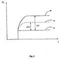
- Limiting or threshold values ⁇ Tr see Fig. 3, can be empirically established for each current value used.
- One method to measure the resistance in a lamp circuit comprises to measure the voltage across the lamp circuit and across a resistor (not shown) placed in series with the lamp circuit. The quotient between these voltages multiplied with the value of the resistor is equal to the resistance of the lamp circuit.
- the resistance of a lamp, used for airfield lighting, is of the same order as the cable supplying the lamp.
- the resistance of a 45 W lamp fed by 6.6 A, which is a common current used in bad visibility, is in the order of 1 ohm.
- the resistance of the same lamp fed by 2.8 A, which is a common current used during good visibility, is about 0.5 ⁇ .
- a typical supply cable has a resistance of about 0,014 ⁇ /m for one pair of 2,5 mm 2 conductors.
- a monitoring unit In monitoring systems, where lamps are individually monitored, a monitoring unit is not likely to be located together with the lamp. Lack of space locates the monitoring unit together with the isolation transformer in a transformer pit. Hence the secondary cable from the monitoring unit to the lamp can typically have a length of 30 to 40 m, which corresponds to a resistance in the order of 0,5 ⁇ . A change in resistance, even due to a complete filament shortage, can therefore be very small in comparison with the resistance of the cables.
- the cable resistance varies as a function of the cable temperature, which is another complicating factor when impedance measurements are carried out from a distance.
- Fig. 3 schematically illustrates how a lamp filament resistance changes in time.
- the voltage U L across the lamp circuit 11 is measured on a time basis t.
- Fig. 3 It is schematically illustrated in Fig. 3 how the voltage U L would be on a constant higher voltage in time, curve 40, if the lamp 4 did not deteriorate or be partly shorted. Further, curve 42, a broken line, depicts how the voltage drops when the lamp is deteriorated or partly shorted. Finally it can be seen how the voltage U L drops to a lower constant value 44 for a totally shorted lamp.
- a cold filament has a resistance value coinciding with the resistance value for a shorted lamp in accordance with the constant voltage 44 of a totally shorted lamp 4.
- the present invention comprises a monitoring arrangement providing detection of deteriorated lamp filaments in a lamp circuit fed by constant current.
- the arrangement provides a lamp monitoring means 10 connected to the lamp circuit 11, which among other tasks detects that a change in said constant current is initiated to flow through the lamp circuit.
- the control unit 36 measures the voltage drop ⁇ Tr in this embodiment of the invention. Further, in accordance with the schematic drawing in Fig. 3, and as an example of a threshold value, ⁇ Tr is set as the limiting or threshold value, so when the voltage U L drops to the constant voltage level 42 due to lamp deterioration, the LMS circuit 10 signals, e.g. to the CU 22, that a replacement of lamp 4 must be accomplished.
- I t further provides resistance determining means, which determine a resistance value across a lamp circuit 11 i.a. by measuring voltage levels as described above, once directly after said current change and once a predetermined time period later.
- resistance determining means determine a resistance value across a lamp circuit 11 i.a. by measuring voltage levels as described above, once directly after said current change and once a predetermined time period later.
- a difference measuring means measuring the difference value between the measured resistance values and a evaluation means for evaluating said resistance difference value compared with a threshold value for said difference is provided.
- the difference between the determined resistance constitutes a sign of the deterioration of a lamp filament compared with the resistance threshold value deduced out off the described voltage drop measurements. This accomplishes that a record keeping of previous resistance determinations or measurements is unnecessary. It is thus established, in real time, how much the lamp filament has been shorted, or the deterioration of it, by comparing the measurements made with a threshold value.
- a lamp can thus be replaced when the resistance difference is equal to or smaller then the resistance threshold value, which is proportional to the voltage threshold value ⁇ Tr in accordance with Ohm's law.
- a resistance is measured and determined by measuring the voltage across a lamp circuit and across a resistor (not shown) placed in series with the lamp circuit 11. The quotient between the determined values multiplied with the value of the resistor is equal to the resistance of the lamp circuit.
- the threshold value is different for different current values, which is advantageous in taking account for different operation conditions regarding the loops 2, including lamps, such as heavy load, minor load etc.
- the threshold values are empirically established for each current value in one embodiment of the present invention.
Landscapes
- Circuit Arrangement For Electric Light Sources In General (AREA)
- Traffic Control Systems (AREA)
- Materials For Medical Uses (AREA)
- Yarns And Mechanical Finishing Of Yarns Or Ropes (AREA)
- Investigating Or Analyzing Materials By The Use Of Magnetic Means (AREA)
- Geophysics And Detection Of Objects (AREA)
- Treatment Of Fiber Materials (AREA)
- Testing Of Short-Circuits, Discontinuities, Leakage, Or Incorrect Line Connections (AREA)
Abstract
Description
Claims (12)
- A method providing detection of deteriorated lamp filaments (3) in a lamp circuit (11) fed by constant current, characterized in that a change in the constant current fed through the lamp circuit (11) is initiated, determining the resistance once directly after the current change and once a predetermined time period later, whereby the difference between the resistance determinations constitutes a sign of the deterioration of a lamp filament (3) in comparison with a threshold value for said difference, thereby avoiding a record keeping of previous resistance determinations.
- A method according to claim 1, characterized in that a lamp (4) should be replaced when said resistance difference is equal to or smaller than the threshold value.
- A method according to claims 1 or 2, characterized in that a resistance is determined and determined by determining the voltage (UL) across a lamp circuit (11) and across a resistor placed in series with the lamp circuit, whereby the quotient between said determined values multiplied with the value of said resistor is equal to the resistance of the lamp circuit (11).
- A method according to claims 1-3, characterized in that said threshold value is different for different current values.
- A method according to claims 1-3, characterized in that said threshold value is different for different nominal wattages of lamps.
- A method according to claim 4-5, characterized in that said threshold values are empirically established for each constant current.
- A monitoring arrangement providing detection of deteriorated lamp filaments (3) in a lamp circuit (11) fed by constant current, characterized in that it comprises:lamp monitoring means (10) connected to said lamp circuit (11), which detects that a change in said constant current is initiated to flow through said lamp circuit (11);resistance determining means, which determine a resistance value across the lamp circuit (11) once directly after said current change and once a predetermined time period later;difference determining means determining a difference value between said determined resistance values;evaluation means for evaluating said resistance difference value compared with a threshold value for said difference; andwhereby the difference between the resistance determinations constitutes a sign of the deterioration of a lamp filament (3) compared with said threshold value (ΔTr), thereby avoiding a record keeping of previous resistance determinations.
- An arrangement according to claim 7, characterized in that a lamp (4) can be replaced when said resistance difference is equal to or smaller than the threshold value.
- An arrangement according to claim 7 or 8, characterized in that a resistance is determined by measuring the voltage across the lamp circuit (11) and across a resistor placed in series with the lamp circuit, whereby the quotient between said determined values multiplied with the value of said resistor is equal to the resistance of the lamp circuit (11).
- An arrangement according to claims 7-9, characterized in that said threshold value (ΔTr) is different for different current values.
- An arrangement according to claims 7-9, characterized in that said threshold value (ΔTr) is different for different nominal wattages of lamps (4).
- An arrangement according to claim 10-11, characterized in that said threshold values (ΔTr) are empirically established for each current value.
Applications Claiming Priority (3)
| Application Number | Priority Date | Filing Date | Title |
|---|---|---|---|
| SE9803620 | 1998-10-22 | ||
| SE9803620A SE515414C2 (en) | 1998-10-22 | 1998-10-22 | Method and apparatus for detecting deteriorated lamp filaments |
| PCT/SE1999/001877 WO2000024229A1 (en) | 1998-10-22 | 1999-10-19 | Deteriorated filament detection |
Publications (2)
| Publication Number | Publication Date |
|---|---|
| EP1121839A1 EP1121839A1 (en) | 2001-08-08 |
| EP1121839B1 true EP1121839B1 (en) | 2004-06-09 |
Family
ID=20413051
Family Applications (1)
| Application Number | Title | Priority Date | Filing Date |
|---|---|---|---|
| EP99970833A Expired - Lifetime EP1121839B1 (en) | 1998-10-22 | 1999-10-19 | Deteriorated filament detection |
Country Status (12)
| Country | Link |
|---|---|
| US (1) | US6556017B1 (en) |
| EP (1) | EP1121839B1 (en) |
| JP (1) | JP4535621B2 (en) |
| CN (1) | CN1239051C (en) |
| AT (1) | ATE268979T1 (en) |
| AU (1) | AU1427600A (en) |
| BR (1) | BR9914680A (en) |
| CA (1) | CA2347483C (en) |
| DE (1) | DE69917920T2 (en) |
| ES (1) | ES2221481T3 (en) |
| SE (1) | SE515414C2 (en) |
| WO (1) | WO2000024229A1 (en) |
Families Citing this family (18)
| Publication number | Priority date | Publication date | Assignee | Title |
|---|---|---|---|---|
| US6666786B2 (en) * | 2000-12-29 | 2003-12-23 | Shimano Inc. | Chamfered sprocket assembly |
| US6784667B2 (en) * | 2002-04-03 | 2004-08-31 | The United States Of America As Represented By The Secretary Of The Navy | Estimated remaining lamp life indicator system |
| US6911777B1 (en) * | 2003-08-14 | 2005-06-28 | Cooper Industries, Inc. | Clamp-on low power isolation transformer for airfield lighting |
| US7924021B2 (en) * | 2003-12-11 | 2011-04-12 | Conti Temic Microelectronic, Gmbh | Procedure for testing the function of a lamp circuit |
| WO2007122546A2 (en) * | 2006-04-21 | 2007-11-01 | Koninklijke Philips Electronics N.V. | Method and device for monitoring the condition of halogen bulbs in vehicle headlights |
| EP1865756A1 (en) * | 2006-06-06 | 2007-12-12 | Nesa A/S | Lighting system |
| US7382454B1 (en) | 2006-09-24 | 2008-06-03 | Carl Anthony Turner | System and method for optically assessing lamp condition |
| US7560867B2 (en) * | 2006-10-17 | 2009-07-14 | Access Business Group International, Llc | Starter for a gas discharge light source |
| FR2919458B1 (en) * | 2007-07-25 | 2009-10-16 | Sidel Participations | METHOD FOR DETECTING THE CONDITION OF A THERMOPLASTIC HEAT BODY HEATING LAMP AND AGENT HEATER FOR IMPLEMENTING SAID LAMP |
| TWI445457B (en) | 2011-01-04 | 2014-07-11 | Beyond Innovation Tech Co Ltd | Driving apparatus for fluorescent tube and method thereof and illumination apparatus using the same |
| US9008992B2 (en) | 2011-03-25 | 2015-04-14 | Thomas & Betts International, Inc. | Testing and monitoring an electrical system |
| JP5812292B2 (en) * | 2012-03-29 | 2015-11-11 | 東芝ライテック株式会社 | Beacon lights and beacon systems |
| WO2014013452A2 (en) * | 2012-07-19 | 2014-01-23 | Koninklijke Philips N.V. | Lighting device comprising a monitoring circuit |
| JP2014182883A (en) * | 2013-03-18 | 2014-09-29 | Toshiba Lighting & Technology Corp | Serial load control device and marker lamp device |
| GB2506708B (en) * | 2013-05-01 | 2014-09-03 | Mk Test Systems | Method for testing equipment |
| US9472108B2 (en) | 2014-03-17 | 2016-10-18 | Honeywell International Inc. | Updating an airfield lighting system with an LED light source |
| DE102017210681A1 (en) * | 2017-06-26 | 2018-12-27 | Dr. Johannes Heidenhain Gesellschaft Mit Beschränkter Haftung | Sensor circuitry |
| CN112596558B (en) * | 2020-12-25 | 2022-06-28 | 航电中和山东医疗技术有限公司 | Heating pipe temperature monitoring device and method |
Family Cites Families (7)
| Publication number | Priority date | Publication date | Assignee | Title |
|---|---|---|---|---|
| JPS55165541A (en) | 1979-06-11 | 1980-12-24 | Mitsubishi Electric Corp | Electron gun |
| JPH0752677B2 (en) * | 1988-08-31 | 1995-06-05 | ホーヤ株式会社 | Lamp abnormality detection circuit and lamp switching device |
| SE9300193L (en) * | 1992-11-20 | 1994-05-21 | Airport Tech Scandinavia | Method and system of communication from the secondary side of a transformer, in particular for a lamp monitoring system for airport lights |
| JP3536933B2 (en) * | 1993-03-31 | 2004-06-14 | 東芝ライテック株式会社 | Incandescent dimmer |
| US5578998A (en) * | 1995-03-20 | 1996-11-26 | Chivas Products Limited | Method and apparatus for predicting of lamp failure |
| JPH09232083A (en) * | 1996-02-26 | 1997-09-05 | Sansha Electric Mfg Co Ltd | Lighting equipment |
| US5675246A (en) * | 1996-03-18 | 1997-10-07 | Msx, Inc. | Current flow indicator |
-
1998
- 1998-10-22 SE SE9803620A patent/SE515414C2/en unknown
-
1999
- 1999-10-19 DE DE69917920T patent/DE69917920T2/en not_active Expired - Lifetime
- 1999-10-19 US US09/807,812 patent/US6556017B1/en not_active Expired - Lifetime
- 1999-10-19 ES ES99970833T patent/ES2221481T3/en not_active Expired - Lifetime
- 1999-10-19 AU AU14276/00A patent/AU1427600A/en not_active Abandoned
- 1999-10-19 CN CNB99812382XA patent/CN1239051C/en not_active Expired - Fee Related
- 1999-10-19 CA CA002347483A patent/CA2347483C/en not_active Expired - Fee Related
- 1999-10-19 EP EP99970833A patent/EP1121839B1/en not_active Expired - Lifetime
- 1999-10-19 JP JP2000577862A patent/JP4535621B2/en not_active Expired - Fee Related
- 1999-10-19 BR BR9914680-0A patent/BR9914680A/en not_active Application Discontinuation
- 1999-10-19 AT AT99970833T patent/ATE268979T1/en not_active IP Right Cessation
- 1999-10-19 WO PCT/SE1999/001877 patent/WO2000024229A1/en not_active Ceased
Also Published As
| Publication number | Publication date |
|---|---|
| ES2221481T3 (en) | 2004-12-16 |
| BR9914680A (en) | 2001-07-24 |
| EP1121839A1 (en) | 2001-08-08 |
| CN1239051C (en) | 2006-01-25 |
| US6556017B1 (en) | 2003-04-29 |
| CN1330854A (en) | 2002-01-09 |
| DE69917920D1 (en) | 2004-07-15 |
| DE69917920T2 (en) | 2005-06-09 |
| SE9803620L (en) | 2000-04-23 |
| SE515414C2 (en) | 2001-07-30 |
| JP2002528871A (en) | 2002-09-03 |
| CA2347483C (en) | 2009-02-03 |
| ATE268979T1 (en) | 2004-06-15 |
| WO2000024229A1 (en) | 2000-04-27 |
| JP4535621B2 (en) | 2010-09-01 |
| CA2347483A1 (en) | 2000-04-27 |
| SE9803620D0 (en) | 1998-10-22 |
| AU1427600A (en) | 2000-05-08 |
Similar Documents
| Publication | Publication Date | Title |
|---|---|---|
| US6556017B1 (en) | Deteriorated filament detection | |
| US5034659A (en) | Lamp circuit with disconnected lamp detecting device | |
| JPH03272595A (en) | Detecting device for broken filament in lamp | |
| US9358921B2 (en) | LED signal lamp | |
| US5625260A (en) | Systems and methods for transmitting pulse signals | |
| KR200283297Y1 (en) | Device for sensing and displaying the trouble of the streetlamp | |
| US4730163A (en) | Device for testing high-pressure lamps and components used therewith | |
| CN101283629B (en) | Method and constant current regulator for controlling series circuit current of signal light facilities at airports etc. | |
| JP6744183B2 (en) | Ground fault current detector | |
| US7196633B2 (en) | Integrated radio tower light controller and alarm reporting device | |
| KR102916803B1 (en) | The smart traffic lights capable of self-diagnosis and the control method thereof | |
| CN206559701U (en) | A kind of navaid loop fault register control and voyage aid of the airport lamp control system | |
| KR102208981B1 (en) | Outdoor light system capable of fault diagnosis and control method thereof | |
| US7282869B1 (en) | HID ballast and lamp tester | |
| JP4720513B2 (en) | Emergency lighting system | |
| JP2923325B2 (en) | Light core break detector | |
| JPH03194898A (en) | Lamp broken-wire detector | |
| JP3074048B2 (en) | Disconnection detection device for series lighting circuit | |
| JP2547842B2 (en) | Disconnection detection device for series lighting circuit | |
| JP2000315591A (en) | Light life judgment device | |
| JP2675660B2 (en) | Light core break detector | |
| GB2318932A (en) | Fluorescent lamp failure warning device | |
| EP0944295B1 (en) | Safety device for lighting systems formed by a plurality of lamps connected in series | |
| JPH0348880Y2 (en) | ||
| JPH03257793A (en) | Filament cut detecting device for series lighting circuit |
Legal Events
| Date | Code | Title | Description |
|---|---|---|---|
| PUAI | Public reference made under article 153(3) epc to a published international application that has entered the european phase |
Free format text: ORIGINAL CODE: 0009012 |
|
| 17P | Request for examination filed |
Effective date: 20010406 |
|
| AK | Designated contracting states |
Kind code of ref document: A1 Designated state(s): AT BE CH CY DE DK ES FI FR GB GR IE IT LI LU MC NL PT SE |
|
| GRAP | Despatch of communication of intention to grant a patent |
Free format text: ORIGINAL CODE: EPIDOSNIGR1 |
|
| RIN1 | Information on inventor provided before grant (corrected) |
Inventor name: PETTERSSON, AKE |
|
| GRAS | Grant fee paid |
Free format text: ORIGINAL CODE: EPIDOSNIGR3 |
|
| GRAA | (expected) grant |
Free format text: ORIGINAL CODE: 0009210 |
|
| AK | Designated contracting states |
Kind code of ref document: B1 Designated state(s): AT BE CH CY DE DK ES FI FR GB GR IE IT LI LU MC NL PT |
|
| PG25 | Lapsed in a contracting state [announced via postgrant information from national office to epo] |
Ref country code: NL Free format text: LAPSE BECAUSE OF FAILURE TO SUBMIT A TRANSLATION OF THE DESCRIPTION OR TO PAY THE FEE WITHIN THE PRESCRIBED TIME-LIMIT Effective date: 20040609 Ref country code: LI Free format text: LAPSE BECAUSE OF FAILURE TO SUBMIT A TRANSLATION OF THE DESCRIPTION OR TO PAY THE FEE WITHIN THE PRESCRIBED TIME-LIMIT Effective date: 20040609 Ref country code: FI Free format text: LAPSE BECAUSE OF FAILURE TO SUBMIT A TRANSLATION OF THE DESCRIPTION OR TO PAY THE FEE WITHIN THE PRESCRIBED TIME-LIMIT Effective date: 20040609 Ref country code: CY Free format text: LAPSE BECAUSE OF FAILURE TO SUBMIT A TRANSLATION OF THE DESCRIPTION OR TO PAY THE FEE WITHIN THE PRESCRIBED TIME-LIMIT Effective date: 20040609 Ref country code: CH Free format text: LAPSE BECAUSE OF FAILURE TO SUBMIT A TRANSLATION OF THE DESCRIPTION OR TO PAY THE FEE WITHIN THE PRESCRIBED TIME-LIMIT Effective date: 20040609 Ref country code: AT Free format text: LAPSE BECAUSE OF FAILURE TO SUBMIT A TRANSLATION OF THE DESCRIPTION OR TO PAY THE FEE WITHIN THE PRESCRIBED TIME-LIMIT Effective date: 20040609 |
|
| REG | Reference to a national code |
Ref country code: GB Ref legal event code: FG4D |
|
| REG | Reference to a national code |
Ref country code: CH Ref legal event code: EP |
|
| REF | Corresponds to: |
Ref document number: 69917920 Country of ref document: DE Date of ref document: 20040715 Kind code of ref document: P |
|
| REG | Reference to a national code |
Ref country code: IE Ref legal event code: FG4D |
|
| PG25 | Lapsed in a contracting state [announced via postgrant information from national office to epo] |
Ref country code: GR Free format text: LAPSE BECAUSE OF FAILURE TO SUBMIT A TRANSLATION OF THE DESCRIPTION OR TO PAY THE FEE WITHIN THE PRESCRIBED TIME-LIMIT Effective date: 20040909 Ref country code: DK Free format text: LAPSE BECAUSE OF FAILURE TO SUBMIT A TRANSLATION OF THE DESCRIPTION OR TO PAY THE FEE WITHIN THE PRESCRIBED TIME-LIMIT Effective date: 20040909 |
|
| PG25 | Lapsed in a contracting state [announced via postgrant information from national office to epo] |
Ref country code: LU Free format text: LAPSE BECAUSE OF NON-PAYMENT OF DUE FEES Effective date: 20041019 Ref country code: IE Free format text: LAPSE BECAUSE OF NON-PAYMENT OF DUE FEES Effective date: 20041019 |
|
| PG25 | Lapsed in a contracting state [announced via postgrant information from national office to epo] |
Ref country code: MC Free format text: LAPSE BECAUSE OF NON-PAYMENT OF DUE FEES Effective date: 20041031 |
|
| NLV1 | Nl: lapsed or annulled due to failure to fulfill the requirements of art. 29p and 29m of the patents act | ||
| REG | Reference to a national code |
Ref country code: CH Ref legal event code: PL |
|
| REG | Reference to a national code |
Ref country code: ES Ref legal event code: FG2A Ref document number: 2221481 Country of ref document: ES Kind code of ref document: T3 |
|
| ET | Fr: translation filed | ||
| PLBE | No opposition filed within time limit |
Free format text: ORIGINAL CODE: 0009261 |
|
| STAA | Information on the status of an ep patent application or granted ep patent |
Free format text: STATUS: NO OPPOSITION FILED WITHIN TIME LIMIT |
|
| 26N | No opposition filed |
Effective date: 20050310 |
|
| REG | Reference to a national code |
Ref country code: IE Ref legal event code: MM4A |
|
| PG25 | Lapsed in a contracting state [announced via postgrant information from national office to epo] |
Ref country code: PT Free format text: LAPSE BECAUSE OF NON-PAYMENT OF DUE FEES Effective date: 20041109 |
|
| REG | Reference to a national code |
Ref country code: FR Ref legal event code: PLFP Year of fee payment: 17 |
|
| PGFP | Annual fee paid to national office [announced via postgrant information from national office to epo] |
Ref country code: ES Payment date: 20150915 Year of fee payment: 17 |
|
| PGFP | Annual fee paid to national office [announced via postgrant information from national office to epo] |
Ref country code: FR Payment date: 20150908 Year of fee payment: 17 |
|
| PGFP | Annual fee paid to national office [announced via postgrant information from national office to epo] |
Ref country code: GB Payment date: 20151014 Year of fee payment: 17 Ref country code: DE Payment date: 20151013 Year of fee payment: 17 Ref country code: IT Payment date: 20151026 Year of fee payment: 17 |
|
| PGFP | Annual fee paid to national office [announced via postgrant information from national office to epo] |
Ref country code: BE Payment date: 20151012 Year of fee payment: 17 |
|
| PG25 | Lapsed in a contracting state [announced via postgrant information from national office to epo] |
Ref country code: BE Free format text: LAPSE BECAUSE OF NON-PAYMENT OF DUE FEES Effective date: 20161031 |
|
| REG | Reference to a national code |
Ref country code: DE Ref legal event code: R119 Ref document number: 69917920 Country of ref document: DE |
|
| GBPC | Gb: european patent ceased through non-payment of renewal fee |
Effective date: 20161019 |
|
| REG | Reference to a national code |
Ref country code: FR Ref legal event code: ST Effective date: 20170630 |
|
| PG25 | Lapsed in a contracting state [announced via postgrant information from national office to epo] |
Ref country code: GB Free format text: LAPSE BECAUSE OF NON-PAYMENT OF DUE FEES Effective date: 20161019 Ref country code: FR Free format text: LAPSE BECAUSE OF NON-PAYMENT OF DUE FEES Effective date: 20161102 Ref country code: DE Free format text: LAPSE BECAUSE OF NON-PAYMENT OF DUE FEES Effective date: 20170503 |
|
| PG25 | Lapsed in a contracting state [announced via postgrant information from national office to epo] |
Ref country code: IT Free format text: LAPSE BECAUSE OF NON-PAYMENT OF DUE FEES Effective date: 20161019 |
|
| REG | Reference to a national code |
Ref country code: BE Ref legal event code: MM Effective date: 20161031 |
|
| PG25 | Lapsed in a contracting state [announced via postgrant information from national office to epo] |
Ref country code: ES Free format text: LAPSE BECAUSE OF FAILURE TO SUBMIT A TRANSLATION OF THE DESCRIPTION OR TO PAY THE FEE WITHIN THE PRESCRIBED TIME-LIMIT Effective date: 20040609 |
|
| REG | Reference to a national code |
Ref country code: ES Ref legal event code: FD2A Effective date: 20181119 |
|
| RIC2 | Information provided on ipc code assigned after grant |
Ipc: H05B 37/03 20060101AFI20000502BHEP |
|
| PG25 | Lapsed in a contracting state [announced via postgrant information from national office to epo] |
Ref country code: ES Free format text: LAPSE BECAUSE OF FAILURE TO SUBMIT A TRANSLATION OF THE DESCRIPTION OR TO PAY THE FEE WITHIN THE PRESCRIBED TIME-LIMIT Effective date: 20161020 |