EP1121570B1 - Apparatus for minimizing the effects of laser intensity reduction at cold temperatures in ring laser gyros - Google Patents
Apparatus for minimizing the effects of laser intensity reduction at cold temperatures in ring laser gyros Download PDFInfo
- Publication number
- EP1121570B1 EP1121570B1 EP99969979A EP99969979A EP1121570B1 EP 1121570 B1 EP1121570 B1 EP 1121570B1 EP 99969979 A EP99969979 A EP 99969979A EP 99969979 A EP99969979 A EP 99969979A EP 1121570 B1 EP1121570 B1 EP 1121570B1
- Authority
- EP
- European Patent Office
- Prior art keywords
- current
- temperature
- ring laser
- controller
- laser gyro
- Prior art date
- Legal status (The legal status is an assumption and is not a legal conclusion. Google has not performed a legal analysis and makes no representation as to the accuracy of the status listed.)
- Expired - Lifetime
Links
- 230000000694 effects Effects 0.000 title description 3
- 230000007423 decrease Effects 0.000 claims description 10
- 239000000463 material Substances 0.000 description 5
- 238000010586 diagram Methods 0.000 description 3
- 230000009286 beneficial effect Effects 0.000 description 2
- 230000003247 decreasing effect Effects 0.000 description 2
- 230000001419 dependent effect Effects 0.000 description 2
- 230000035559 beat frequency Effects 0.000 description 1
- 238000005352 clarification Methods 0.000 description 1
- 239000000835 fiber Substances 0.000 description 1
- 230000004048 modification Effects 0.000 description 1
- 238000012986 modification Methods 0.000 description 1
- 230000000717 retained effect Effects 0.000 description 1
- 239000002699 waste material Substances 0.000 description 1
Images


Classifications
-
- G—PHYSICS
- G01—MEASURING; TESTING
- G01C—MEASURING DISTANCES, LEVELS OR BEARINGS; SURVEYING; NAVIGATION; GYROSCOPIC INSTRUMENTS; PHOTOGRAMMETRY OR VIDEOGRAMMETRY
- G01C19/00—Gyroscopes; Turn-sensitive devices using vibrating masses; Turn-sensitive devices without moving masses; Measuring angular rate using gyroscopic effects
- G01C19/58—Turn-sensitive devices without moving masses
- G01C19/64—Gyrometers using the Sagnac effect, i.e. rotation-induced shifts between counter-rotating electromagnetic beams
- G01C19/66—Ring laser gyrometers
Definitions
- Ring laser gyros are made of a ring laser gyro block with mirrors at the ends of the block. Legs exist in the ring laser gyro block to create a passageway between the mirrors which laser beams travel through for the operation of a ring laser gyro.
- a current is supplied which is called the run current.
- the run current is supplied to anodes of the ring laser gyro and travel through portions of the legs to the cathode of the ring laser gyro.
- the run current is required for operation of the ring laser gyro in supplying adequate power for lasing in the legs of the ring laser gyro.
- Ring laser gyros currently operate at a fixed run current. The fixed run current level is determined by numerous factors, but is typically set at 2 to 5 times the lasing threshold in order to provide adequate laser power in the ring laser gyro.
- the run current is set at a fixed level to ensure that adequate power exists for the ring laser gyro to operate in all temperature environments.
- the typical temperature range that a ring laser gyro operates in is 85 degrees Celsius to -40 degrees Celsius.
- the run current was fixed at a higher level to accommodate the low temperature range. Though the operation continued to be satisfactory at these lower cold temperatures, the run current was set at an unnecessarily higher level than required for the higher temperatures.
- a ring laser gyro The operation of a ring laser gyro is above 4 degrees Celsius ninety percent of a ring laser gyro's lifetime. Therefore, power is wasted at most of the ring laser gyro's life. Further, in addition to the waste of power, a higher power supply decreases the life of elements within the ring laser gyro such as the mirrors and the cathode due to the higher energy source that degrades these elements. As a result, it would be beneficial if the run current was decreased for the majority of a ring laser gyro's lifetime so that the projected lifetime of the gyro would be increased due to longer life of the ring laser gyro elements such as the mirrors and the cathode. It would be beneficial if the capability existed to control the run current so that it was variable depending on the temperature range that the ring laser gyro operated at so that energy, materials and money could be saved.
- U.S. Patent No. 5,410,515 discloses that the wavelength of the output of a laser that is supplied to a fiber optic gyro is affected by temperature. To compensate for the effect of temperature, the temperature of the gyro is sensed and is processed so that, as temperature decreases, the drive current supplied to the light source also decreases. Thus, the drive current supplied to the laser changes in the same direction as temperature. This relationship between temperature and drive current is not useful for the present invention.
- U.S. Patent No. 4,635,266 discloses a first embodiment in which the drive current supplied by a D/A converter to the laser is controlled in accordance with VF.
- VF is dependent upon (i) an initial reading VA of the laser voltage supplied by a voltmeter, (ii) a final reading VN of the laser voltage supplied by the voltmeter, and (iii) the previously calculated voltage VF designated as V0.
- the drive current supplied by a D/A converter to the laser is again controlled in accordance with VF.
- VF is dependent upon (i) a beat frequency provided in accordance with the output of the laser and an output of a synthesizer, and (ii) the previously calculated voltage VF also designated as V0.
- Neither of these embodiments involve temperature sensing.
- U.S. Patent No. 5,299,211 discloses a temp sensor in Figure 1.
- the temp sensor is presumably a temperature sensor and is connected as an input to a microcontroller.
- the microcontroller controls the supply of current to a ring laser gyro.
- temperature is used in this current control.
- An apparatus for controlling the run current in a ring laser gyro includes the ability for sensing temperature, supplying a current to the ring laser gyro and controlling the current supplied to the ring laser gyro.
- the current varies depending on the temperature the ring laser gyro is operating at The current changes at predetermined temperature points. After a certain temperature point is reached, the run current will be maintained at that maximum current level and will not be increase any further as this maximum current level is the highest current level required for the ring laser gyro to operate at any temperature beyond this temperature point.
- the present invention utilizes multiple circuits to control the run current of a ring laser gyro 2 so that the run current is adjusted depending on the temperature.
- Fig. 1 shows a block diagram of the circuits used in the present invention.
- the circuits used are: a temperature sensor circuit 4, servo IT circuit 6, a reference voltage circuit 7, R sense 8, total current control circuit 10, differential current control circuit 12, and a run voltage circuit 14.
- a current is supplied, by a voltage supply 16 and R sense 8, to the anodes 18 of the ring laser gyro 2 for operation.
- the differential current control circuit 12 monitors the current supplied to the anodes 18 and adjusts the current supplied to the anodes 18 to ensure that the same amount of current is supplied to each anode 18 of the ring laser gyro 2.
- the current travels through the ring laser gyro 2 and exits the ring laser gyro 2 through the cathode 20 of the ring laser gyro 2.
- the total current control circuit 10 detects the voltage at R sense 8 and adjust the run voltage circuit 14 to maintain the proper gyro current
- the run voltage circuit 14 is well known in this area of technology and will not be discussed any further.
- the improvement and advantage of the present invention over what is known in the area of technology is the ability to adjust the run current in relation to the temperature.
- the temperature sensor circuit 4 of the present invention senses the temperature the ring laser gyro 2 is operating at. The sensed temperature is then sent to the servo IT circuit 6.
- the servo IT circuit 6 is set to operate at a predetermined set temperature set by its internal reference. Once this predetermined set temperature is sensed by the temperature sensor circuit 4, the servo IT circuit 6 increases the run current. As stated previously, at very low temperatures, a higher current is required for the operation of the ring laser gyro 2. Therefore, when the temperature drops below this certain set temperature, a higher run current will be required.
- the run current is increased by the servo IT circuit 6 by increasing the voltage over R sense 8 (a resistor arrangement) so that the current supplied to the anodes 18 will increase.
- the total current control circuit 10 operates by adjusting the run voltage so that the voltage at R sense 8 is equal to the reference voltage at the total current control circuit 10.
- the servo IT circuit 6 increases the run current by lowering the reference voltage to the total current control circuit 10 which in turn lowers the run voltage and increases the voltage across R sense 8.
- the run current will continue to be increased until a maximum level has been reached at a second set temperature. The run current will remain at this level while the ring laser gyro 2 is operating in the temperature range below the second set temperature.
- the total current control circuit 10 voltage is 12 volts and the run voltage is -460 volts.
- the voltage supply 16 will be set at supplying 15 volts and therefore, the voltage over R sense 8 will be 3 volts.
- the run voltage will be decreased in order to increase the voltage over R sense 8 which increases the run current to the anodes 18 of the ring laser gyro 2.
- the servo IT 6 senses the need for a change based on the temperature and the total control circuit 10 voltage is lowered to 10 volts which in turn decreases the run voltage to -462 volts.
- the voltage supply 16 remains constant at 15 volts and therefore, the voltage over R sense 8 increases to 5 volts which increases the run current as a result.
- circuitry is shown in Fig. 2. It should be noted that the present invention is not limited to the specific disclosed circuit implementations, but that many other implementations can be used. Further, the present invention is not limited to analog implementations, but any element shown in Fig. 1 could be replaced with a digital implementation. The present invention is providing a structure with the capability to adjust run current taking into account the temperature the ring laser gyro is operating at. As long as this inventive concept is retained, many differing analog or digital implementations can be used. The specific circuit implementation described is the preferred embodiment and is used to disclose an example and not a limitation of a circuit implementation to realize the present invention.
- the temperature sensor 4 is well known in this area of technology and will not be discussed in any further detail here.
- the temperature sensor 4 is connected to the servo IT 6. Specifically in the servo IT circuitry 6, the temperature sensor 4 is connected to a first operational amplifier 30 which is used as a buffer to prevent too much current from being drawn out of the temperature sensor 4.
- a second operational amplifier 32 is connected to the first operational amplifier 30.
- a transistor 34 is in turn connected to the second operational amplifier 32 to initiate the increase in the run current when required.
- These elements increase voltage which along with R sense 8 will increase the run current.
- R sense 8 and the increase in run current will be discussed later, but it should be understood that an increase in voltage will result in an increase in run current.
- the second operational amplifier 32 is set at a first set level voltage which the ring laser gyro 2 operates at the majority of the time. Again, at lower temperatures, more current is required so the run current is increased by increasing the voltage. If the temperature goes below a first predetermined temperature which is a lower temperature, the second operational amplifier 32 "turns on” and in turn “turns on” the transistor 34 so that the voltage output out of the servo IT 6 is increased. The voltage continues to increase until a second predetermined temperature is reached in which a second set level voltage is maintained. The second set level voltage is the maximum level required for ring laser gyro operation regardless of how low the temperature becomes.
- the second operational amplifier 32 reaches a maximum voltage and no further voltage increase is output, but instead, the voltage is maintained at this second set level voltage.
- the increased voltage causes an increase in voltage over R sense 8 which will in turn draw more current from the voltage supply 16.
- the run current supplied to the anodes 18 of the ring laser gyro 2 will increase.
- the two current control circuits 10 and 12 discussed before are well known in this area of technology and will not be discussed in any further detail here.
- the present invention sets the run current at levels adequate for ring laser gyro operation at differing temperatures. As a result, only the necessary amount of current is supplied and money, energy, and materials is saved.
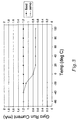
- Fig. 3 shows an example of the operation of the present invention for clarification.
- the chart shows the previously fixed current supply as well as the use of the present invention with the servo IT 6 to control the current supply.
- the current was previously supplied at a fixed level of 1.2 mA.
- the voltage supply 16 is set at supplying a current of approximately .7mA. This run current level is the required level for the operation of the ring laser gyro 2 at temperatures above 4 degrees Celsius. As the temperature lowers, more current is required for the operation of the ring laser gyro 2.
- the servo IT 6 When the temperature sensor 4 senses 4 degrees Celsius, the servo IT 6 will increase the voltage over R sense 8 and thus, increase the current supplied to the anodes 18 of the ring laser gyro 2. As the temperature reaches -20 degrees Celsius and below, it is known that only 1.2 mA is required for the operation of the ring laser gyro 2 at these temperature levels. Once the temperature sensor 4 senses this temperature, the servo IT 6 will cease increasing the voltage over R sense 8 and keep it at a level so that 1.2 mA is supplied to the anodes 18 of the ring laser gyro 2. It is to be noted that the values for temperature and current are used for example purposes only and different temperature or current values can be used for different applications.
Landscapes
- Physics & Mathematics (AREA)
- Engineering & Computer Science (AREA)
- Optics & Photonics (AREA)
- Electromagnetism (AREA)
- Power Engineering (AREA)
- General Physics & Mathematics (AREA)
- Radar, Positioning & Navigation (AREA)
- Remote Sensing (AREA)
- Gyroscopes (AREA)
- Lasers (AREA)
- Semiconductor Lasers (AREA)
Description
Claims (15)
- An apparatus for controlling current supplied to a ring laser gyro (2), the apparatus including a temperature sensor (4) and a controller (6, 7, 8, 10, 12, 14, and/or 16) that varies current supplied to the ring laser gyro as a function of temperature, the apparatus BEING CHARACTERIZED in that:the controller (6, 7, 8, 10, 12, 14, and/or 16) controls the current in an inverse relationship to temperature over at least a portion of a temperature operating range of the ring laser gyro (2).
- The apparatus of claim 1 wherein the controller (6, 7, 8, 10, 12, 14, and/or 16) increases the current supplied to the ring laser gyro (2) when a first predetermined temperature is sensed.
- The apparatus of claim 2 wherein the controller (6, 7, 8, 10, 12, 14, and/or 16) increases the current by increasing a voltage over a resistor configuration (8).
- The apparatus of claim 2 wherein the controller (6, 7, 8, 10, 12, 14, and/or 16) ceases increasing the current supplied to the ring laser gyro (2) when a second predetermined temperature is sensed.
- The apparatus of claim 1 wherein the ring laser gyro (2) comprises first and second anodes (18) and a cathode (20), and wherein the controller (6, 7, 8, 10, 12, 14, and/or 16) includes a differential current control (12) for establishing that equal amounts of current are supplied to the anodes (18).
- The apparatus of claim 5 wherein the controller (6, 7, 8, 10, 12 ,14, and/or 16) includes a total current control (10) to maintain a proper total current through the ring laser gyro (2).
- The apparatus of claim 5 wherein the controller (6, 7, 8, 10, 12, 14, and/or 16) increases the current supplied to the ring laser gyro (2) when a first predetermined temperature is sensed.
- The apparatus of claim 7 wherein the controller (6, 7, 8, 10, 12, 14, and/or 16) increases the current by increasing a voltage over a resistor configuration (8).
- The apparatus of claim 7 wherein the controller (6, 7, 8, 10, 12, 14, and/or 16) ceases increasing the current supplied to the ring laser gyro (2) when a second predetermined temperature is sensed.
- The apparatus of claim 9 wherein the controller (6, 7, 8, 10, 12 ,14, and/or 16) includes a total current control (10) to maintain a proper total current through the ring laser gyro (2).
- The apparatus of claim 5 wherein the controller (6, 7, 8, 10, 12, 14, and/or 16) comprises transistors and operational amplifiers.
- The apparatus of claim 1 wherein the controller (6, 7, 8, 10, 12, 14, and/or 16) controls the current supplied to the ring laser gyro (2) at a substantially constant first current the current supplied to the ring laser gyro (2) at a substantially constant second current level level below a first temperature, wherein the controller (6, 7, 8, 10, 12 ,14, and/or 16) controls above a second temperature, wherein the first current level is greater than the second current level, wherein the first temperature is less than the second temperature, and wherein the controller (6, 7, 8, 10, 12, 14, and/or 16) decreases the current from the first current level to the second current level between the first and second temperatures.
- The apparatus of claim 1 wherein the controller (6, 7, 8, 10, 12 ,14, and/or 16) controls the current supplied to the ring laser gyro (2) at a current level below a temperature, and wherein the controller (6, 7, 8, 10, 12, 14, and/or 16) decreases the current from the current level above the temperature.
- The apparatus of claim 1 wherein the controller (6, 7, 8, 10, 12 ,14, and/or 16) controls the current supplied to the ring laser gyro (2) at a current level above a temperature, and wherein the controller (6, 7, 8, 10, 12, 14, and/or 16) increases the current from the current level below the temperature.
- The apparatus of claim 1 wherein the controller (6,7, 8,10,12,14, and/or 16) controls the current supplied to the ring laser gyro (2) at a first current level at a first temperature, wherein the controller (6, 7, 8, 10, 12, 14, and/or 16) controls the current supplied to the ring laser gyro (2) at a second current level at a second temperature, wherein the first current level is greater than the second current level, wherein the first temperature is less than the second temperature, and wherein the controller (6, 7, 8, 10, 12, 14, and/or 16) decreases the current from the first current level to the second current level between the first and second temperatures.
Applications Claiming Priority (3)
| Application Number | Priority Date | Filing Date | Title |
|---|---|---|---|
| US170532 | 1998-10-13 | ||
| US09/170,532 US6108358A (en) | 1998-10-13 | 1998-10-13 | Apparatus for minimizing the effects of laser intensity reduction at cold temperatures in ring laser gyros |
| PCT/US1999/022599 WO2000028280A2 (en) | 1998-10-13 | 1999-09-29 | Apparatus for minimizing the effects of laser intensity reduction at cold temperatures in ring laser gyros |
Publications (2)
| Publication Number | Publication Date |
|---|---|
| EP1121570A2 EP1121570A2 (en) | 2001-08-08 |
| EP1121570B1 true EP1121570B1 (en) | 2004-11-03 |
Family
ID=22620234
Family Applications (1)
| Application Number | Title | Priority Date | Filing Date |
|---|---|---|---|
| EP99969979A Expired - Lifetime EP1121570B1 (en) | 1998-10-13 | 1999-09-29 | Apparatus for minimizing the effects of laser intensity reduction at cold temperatures in ring laser gyros |
Country Status (7)
| Country | Link |
|---|---|
| US (1) | US6108358A (en) |
| EP (1) | EP1121570B1 (en) |
| JP (1) | JP2002529723A (en) |
| AU (1) | AU742284B2 (en) |
| CA (1) | CA2347490A1 (en) |
| DE (1) | DE69921676T2 (en) |
| WO (1) | WO2000028280A2 (en) |
Families Citing this family (7)
| Publication number | Priority date | Publication date | Assignee | Title |
|---|---|---|---|---|
| US6804826B1 (en) * | 1999-07-28 | 2004-10-12 | Trilithic, Inc. | Radio frequency leakage detection system for CATV system |
| US7486401B2 (en) * | 2006-02-27 | 2009-02-03 | Honeywell International Inc. | Laser medium pumping system for a gyroscope |
| US7916302B2 (en) * | 2007-05-18 | 2011-03-29 | Honeywell International Inc. | Gyroscope mode shift detection and scale factor compensation |
| US8068233B2 (en) * | 2009-05-14 | 2011-11-29 | Honeywell International Inc. | Compact resonator fiber optic gyroscopes |
| JP5628120B2 (en) * | 2011-09-15 | 2014-11-19 | ローム株式会社 | Light emitting element module |
| US8901432B2 (en) | 2011-09-30 | 2014-12-02 | Honeywell International Inc. | Mitigation of block bending in a ring laser gyroscope caused by thermal expansion or compression of a circuit board |
| US8905635B2 (en) | 2011-09-30 | 2014-12-09 | Honeywell International Inc. | Temperature sensor attachment facilitating thermal conductivity to a measurement point and insulation from a surrounding environment |
Family Cites Families (8)
| Publication number | Priority date | Publication date | Assignee | Title |
|---|---|---|---|---|
| US4282495A (en) * | 1979-05-29 | 1981-08-04 | The Singer Company | High efficiency current regulator for ring laser gyroscope |
| US4635266A (en) * | 1984-12-11 | 1987-01-06 | The United States Of America As Represented By The Secretary Of The Air Force | Active dispersion control for a Doppler broadened laser |
| US5076694A (en) * | 1991-02-11 | 1991-12-31 | Rockwell International Corporation | In-flight scale factor calibration of ring laser gyro systems |
| US5719675A (en) * | 1992-06-16 | 1998-02-17 | Honeywell Inc. | Laser gyro life prediction |
| US5299211A (en) * | 1992-08-27 | 1994-03-29 | Honeywell Inc. | Laser gyro high voltage start module and high voltage pulse generator |
| US5410515A (en) * | 1993-04-29 | 1995-04-25 | Honeywell Inc. | Rapid turn-on source for fiber optic gyroscope |
| US5400141A (en) * | 1993-08-31 | 1995-03-21 | Honeywell Inc. | Method and system for minimizing angular random walk or bias in a ring laser gyroscope through the use of temperature based control |
| US5450198A (en) * | 1993-10-01 | 1995-09-12 | Honeywell Inc. | Laser gyro microprocessor based smart mode acquisition and high performance mode hopping |
-
1998
- 1998-10-13 US US09/170,532 patent/US6108358A/en not_active Expired - Lifetime
-
1999
- 1999-09-29 CA CA002347490A patent/CA2347490A1/en not_active Abandoned
- 1999-09-29 JP JP2000581416A patent/JP2002529723A/en active Pending
- 1999-09-29 DE DE69921676T patent/DE69921676T2/en not_active Expired - Fee Related
- 1999-09-29 EP EP99969979A patent/EP1121570B1/en not_active Expired - Lifetime
- 1999-09-29 WO PCT/US1999/022599 patent/WO2000028280A2/en not_active Ceased
- 1999-09-29 AU AU33421/00A patent/AU742284B2/en not_active Ceased
Also Published As
| Publication number | Publication date |
|---|---|
| AU742284B2 (en) | 2001-12-20 |
| DE69921676T2 (en) | 2005-10-20 |
| WO2000028280A2 (en) | 2000-05-18 |
| US6108358A (en) | 2000-08-22 |
| CA2347490A1 (en) | 2000-05-18 |
| AU3342100A (en) | 2000-05-29 |
| EP1121570A2 (en) | 2001-08-08 |
| JP2002529723A (en) | 2002-09-10 |
| WO2000028280A3 (en) | 2000-08-31 |
| DE69921676D1 (en) | 2004-12-09 |
Similar Documents
| Publication | Publication Date | Title |
|---|---|---|
| US5563898A (en) | Semiconductor laser drive | |
| JPH07202301A (en) | Current drive voltage detection laser diode driver | |
| JP2001094202A (en) | Method and control circuit for controlling extinction ratio of laser diode | |
| JP2001053377A (en) | Semiconductor laser driver | |
| KR940004924A (en) | Switch mode power supply | |
| WO1995013575A1 (en) | Power supply controller having low startup current | |
| AU742284B2 (en) | Apparatus for minimizing the effects of laser intensity reduction at cold temperatures in ring laser gyros | |
| US6392215B1 (en) | Laser diode driving circuit | |
| US5489981A (en) | Microprocessor controlled anglaser gyropower control system | |
| US4282495A (en) | High efficiency current regulator for ring laser gyroscope | |
| US6072816A (en) | Laser-diode drive circuit | |
| US7141936B2 (en) | Driving circuit for light emitting diode | |
| US5402432A (en) | Semi-conductor laser device constant power output controller | |
| JPH09237684A (en) | Inverter circuit | |
| JPS5965324A (en) | Temperature control circuit | |
| US6980048B2 (en) | Voltage generating circuit capable of supplying stable output voltage regardless of external input voltage | |
| JP3109467B2 (en) | Optical transmitter | |
| JP2682419B2 (en) | Semiconductor laser drive circuit | |
| US6509543B1 (en) | Semiconductor laser heating apparatus | |
| JPS6151887A (en) | Driving device for semiconductor laser | |
| JP2547849B2 (en) | Automatic laser output control circuit | |
| JPS6163074A (en) | Semiconductor laser diode drive circuit | |
| JP2000261090A (en) | Laser drive circuit | |
| JP2527602B2 (en) | Semiconductor laser drive circuit | |
| JP2938457B2 (en) | Light emitting element drive circuit |
Legal Events
| Date | Code | Title | Description |
|---|---|---|---|
| PUAI | Public reference made under article 153(3) epc to a published international application that has entered the european phase |
Free format text: ORIGINAL CODE: 0009012 |
|
| 17P | Request for examination filed |
Effective date: 20010412 |
|
| AK | Designated contracting states |
Kind code of ref document: A2 Designated state(s): AT BE CH CY DE DK ES FI FR GB GR IE IT LI LU MC NL PT SE |
|
| AX | Request for extension of the european patent |
Free format text: AL;LT;LV;RO;SI |
|
| GRAP | Despatch of communication of intention to grant a patent |
Free format text: ORIGINAL CODE: EPIDOSNIGR1 |
|
| RBV | Designated contracting states (corrected) |
Designated state(s): DE FR GB IT |
|
| GRAS | Grant fee paid |
Free format text: ORIGINAL CODE: EPIDOSNIGR3 |
|
| GRAA | (expected) grant |
Free format text: ORIGINAL CODE: 0009210 |
|
| AK | Designated contracting states |
Kind code of ref document: B1 Designated state(s): DE FR GB IT |
|
| REG | Reference to a national code |
Ref country code: GB Ref legal event code: FG4D |
|
| REF | Corresponds to: |
Ref document number: 69921676 Country of ref document: DE Date of ref document: 20041209 Kind code of ref document: P |
|
| REG | Reference to a national code |
Ref country code: IE Ref legal event code: FG4D |
|
| PGFP | Annual fee paid to national office [announced via postgrant information from national office to epo] |
Ref country code: GB Payment date: 20050809 Year of fee payment: 7 |
|
| PGFP | Annual fee paid to national office [announced via postgrant information from national office to epo] |
Ref country code: FR Payment date: 20050902 Year of fee payment: 7 |
|
| PLBE | No opposition filed within time limit |
Free format text: ORIGINAL CODE: 0009261 |
|
| STAA | Information on the status of an ep patent application or granted ep patent |
Free format text: STATUS: NO OPPOSITION FILED WITHIN TIME LIMIT |
|
| ET | Fr: translation filed | ||
| PGFP | Annual fee paid to national office [announced via postgrant information from national office to epo] |
Ref country code: DE Payment date: 20050930 Year of fee payment: 7 |
|
| 26N | No opposition filed |
Effective date: 20050804 |
|
| PGFP | Annual fee paid to national office [announced via postgrant information from national office to epo] |
Ref country code: IT Payment date: 20060930 Year of fee payment: 8 |
|
| PG25 | Lapsed in a contracting state [announced via postgrant information from national office to epo] |
Ref country code: DE Free format text: LAPSE BECAUSE OF NON-PAYMENT OF DUE FEES Effective date: 20070403 |
|
| GBPC | Gb: european patent ceased through non-payment of renewal fee |
Effective date: 20060929 |
|
| REG | Reference to a national code |
Ref country code: FR Ref legal event code: ST Effective date: 20070531 |
|
| PG25 | Lapsed in a contracting state [announced via postgrant information from national office to epo] |
Ref country code: GB Free format text: LAPSE BECAUSE OF NON-PAYMENT OF DUE FEES Effective date: 20060929 |
|
| PG25 | Lapsed in a contracting state [announced via postgrant information from national office to epo] |
Ref country code: FR Free format text: LAPSE BECAUSE OF NON-PAYMENT OF DUE FEES Effective date: 20061002 |
|
| PG25 | Lapsed in a contracting state [announced via postgrant information from national office to epo] |
Ref country code: IT Free format text: LAPSE BECAUSE OF NON-PAYMENT OF DUE FEES Effective date: 20070929 |
|
| P01 | Opt-out of the competence of the unified patent court (upc) registered |
Effective date: 20230525 |