EP1120926A1 - Article comprising a single-stage all-pass optical filter - Google Patents
Article comprising a single-stage all-pass optical filter Download PDFInfo
- Publication number
- EP1120926A1 EP1120926A1 EP01300309A EP01300309A EP1120926A1 EP 1120926 A1 EP1120926 A1 EP 1120926A1 EP 01300309 A EP01300309 A EP 01300309A EP 01300309 A EP01300309 A EP 01300309A EP 1120926 A1 EP1120926 A1 EP 1120926A1
- Authority
- EP
- European Patent Office
- Prior art keywords
- repetition rate
- filter
- delay
- optical filter
- optical
- Prior art date
- Legal status (The legal status is an assumption and is not a legal conclusion. Google has not performed a legal analysis and makes no representation as to the accuracy of the status listed.)
- Granted
Links
- 230000003287 optical effect Effects 0.000 title claims abstract description 128
- 230000001419 dependent effect Effects 0.000 claims abstract description 12
- 238000001228 spectrum Methods 0.000 claims abstract description 10
- 238000004891 communication Methods 0.000 claims description 14
- 230000003595 spectral effect Effects 0.000 claims description 4
- 238000010438 heat treatment Methods 0.000 claims description 3
- 238000000034 method Methods 0.000 claims 7
- 230000005540 biological transmission Effects 0.000 claims 2
- 230000008878 coupling Effects 0.000 description 9
- 238000010168 coupling process Methods 0.000 description 9
- 238000005859 coupling reaction Methods 0.000 description 9
- 230000003111 delayed effect Effects 0.000 description 7
- 239000000835 fiber Substances 0.000 description 5
- 230000001360 synchronised effect Effects 0.000 description 5
- 239000013307 optical fiber Substances 0.000 description 4
- 239000006185 dispersion Substances 0.000 description 3
- 230000000694 effects Effects 0.000 description 3
- 230000005693 optoelectronics Effects 0.000 description 2
- 230000009286 beneficial effect Effects 0.000 description 1
- 230000001934 delay Effects 0.000 description 1
- 238000001914 filtration Methods 0.000 description 1
- 238000004519 manufacturing process Methods 0.000 description 1
- 238000012986 modification Methods 0.000 description 1
- 230000004048 modification Effects 0.000 description 1
- 230000004044 response Effects 0.000 description 1
Images

Classifications
-
- H—ELECTRICITY
- H04—ELECTRIC COMMUNICATION TECHNIQUE
- H04J—MULTIPLEX COMMUNICATION
- H04J14/00—Optical multiplex systems
- H04J14/08—Time-division multiplex systems
-
- G—PHYSICS
- G02—OPTICS
- G02B—OPTICAL ELEMENTS, SYSTEMS OR APPARATUS
- G02B5/00—Optical elements other than lenses
- G02B5/20—Filters
-
- H—ELECTRICITY
- H04—ELECTRIC COMMUNICATION TECHNIQUE
- H04B—TRANSMISSION
- H04B10/00—Transmission systems employing electromagnetic waves other than radio-waves, e.g. infrared, visible or ultraviolet light, or employing corpuscular radiation, e.g. quantum communication
- H04B10/50—Transmitters
- H04B10/501—Structural aspects
- H04B10/503—Laser transmitters
- H04B10/504—Laser transmitters using direct modulation
-
- H—ELECTRICITY
- H04—ELECTRIC COMMUNICATION TECHNIQUE
- H04B—TRANSMISSION
- H04B10/00—Transmission systems employing electromagnetic waves other than radio-waves, e.g. infrared, visible or ultraviolet light, or employing corpuscular radiation, e.g. quantum communication
- H04B10/50—Transmitters
- H04B10/508—Pulse generation, e.g. generation of solitons
Definitions
- the present invention relates to optical communications systems and more particularly, to an article comprising a single-stage all-pass optical filter.
- Optical communications systems typically include a variety of devices (e.g., light sources, photodetectors, switches, optical fibers, amplifiers, filters, and so forth). Optical communications systems are useful for transmitting optical signals over long distances at high speeds.
- An optical signal which comprises a series of light pulses, is transmitted from a light source such as a laser to an optical fiber and ultimately to a detector.
- Amplifiers and filters may be used to propagate the light pulses along the length of the fiber from the light source to the detector.
- Today, the bulk of long-distance communication traffic is carried by optical fibers. As use of optical fibers becomes more widespread and infiltrates the consumer marketplace, demand is increasing for efficient, high-speed, integrated opto-electronic devices.
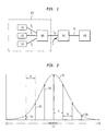
- FIG. 1 reflects a schematic representation of an OTDM system, comprising a time-division multiplexer (TDM) 100 which includes a plurality of low-speed transmitters 102, 103, 104 and a multiplexer 105, an optical switch or demultiplexer 110, and a receiver 115, connected by trunk fiber 11.
- TDM time-division multiplexer
- Each of the transmitters sends low speed signals (s L ) to the multiplexer 105 which then outputs a high speed signal (s H ) to the switch 110.
- the switch selectively drops pulses from the high-speed signal to produce low-speed output signals (s O ) sent to receiver 115.
- the signals may be sent at high-speed over the length of the fiber between the multiplexer 105 and the switch 110, and then interpreted at low speed to determine the information sent from each one of the transmitters.
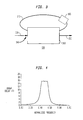
- FIG. 2 is a graphical illustration showing the spectrum of an unmodulated pulse train.
- an optical pulse 10 typically comprises a packet of waves 15a, 15b, 15c ...
- Each wave has a certain amplitude and frequency within the bandwidth f, e.g., each wave within the packet is characterized by a different frequency and amplitude and travels at a different speed. Challenges are involved in achieving a constant time delay for each of the frequencies over the entire bandwidth f . If certain frequencies of the pulse train (e.g. 15a, 15b), are not delayed or are given a different period of delay than other frequencies (e.g., 15c, 15d), the delayed signal will not correspond in phase with the original pulse train.
- certain frequencies of the pulse train e.g. 15a, 15b
- other frequencies e.g., 15c, 15d
- All-pass filters have been known in the field of electronics for equalizing phase and reducing distortion. Structures for fabricating all-pass filters for electronic devices are known in the field and described in the literature. See, e.g., U.S. Pat. No. 5,258,716 to Kondo et al ., " All-Pass Filter.” All-pass filters provide advantages over other types of filters as they affect only the phase of a signal, rather than its amplitude. A configuration for an all-pass filter for use with optical devices is described in EP-A-0 997 751; filed by Kazarinov et al .
- an optical signal transmitted through a fiber may be distorted or broadened with time over the length of the fiber. This broadening is undesirable as it may create noise, i . e ., interference between sequential optical pulses.
- the Kazarinov et al. application describes an all-pass optical filter designed to eliminate such distortions. Additionally, it was disclosed therein that the all-pass optical filter could be useful in delaying an optical pulse in time.
- the all-pass optical filter of the Kazarinov et al. application applies a frequency-dependent time delay to each frequency of the optical pulse.
- the Kazarinov et al. application describes single-stage and multiple-stage all-pass optical filters.
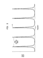
- a schematic representation of one embodiment a single-stage all-pass optical filter according to the Kazarinov et al. application is illustrated in FIG. 3.
- the filter comprises an input port for an input optical pulse 120, an output port 150, a splitter/combiner 143, and a feedback path 145 wherein the feedback path advantageously comprises at least one ring resonator.
- FIG. 3 shows a single-stage filter (e.g., a single resonator ring)
- the Kazarinov et al. application discloses that best results are achieved when multiple stages (multiple resonator rings) are used. Indeed, the Kazarinov et al.
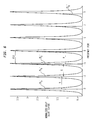
- FIG. 4 is a graph of the group delay in units of time as a function of frequency for a four-stage all pass optical filter as applied to an arbitrary broadband signal.
- a maximum and fairly constant delay of 16 au is achieved over the normalized frequency range of 0.4 to 0.6.
- a single all-pass optical filter would achieve a constant delay over a much smaller frequency range ( ⁇ 05) and thus would be ineffective in delaying a pulse train having a large bandwidth ( ⁇ f ).
- the four-stage all-pass optical filter used to produce the delay peak shown in FIG. 4 would include the use of eight heaters, each of which would be need to be periodically adjusted depending on the optical signal and desired phase response.
- the invention embraces an article comprising a single-stage all-pass optical filter.
- the all-pass optical filter includes an input port for receiving an input optical pulse having a regular repetition rate; an output port; a splitter/combiner; and one feedback path.
- the all-pass optical filter is configured to apply a plurality of frequency-dependent time delay periods to the input optical pulse so that the filter is characterized by a time-delay spectrum having a plurality of delay peaks.
- the free-spectral range (FSR) of the filter i.e., the spacing between the delay peaks, is matched to the regular repetition rate of the input optical pulse.
- the FSR being equal to the repetition rate or offset from the repetition rate to a sufficiently small degree that each frequency of the pulse train will fall within the bandwidth of one of the plurality of delay peaks.
- at least one heater is disposed on the feedback path for use in tuning the time-delay spectrum of the filter.
- the article including the single-stage all-pass optical filter may comprise an assembly for use in a communications system including an OTDM device or a pulsed laser.
- the invention comprises a single stage all-pass optical filter that can be used to generate a large tunable delay for a regular unmodulated pulse train.
- a single-stage all-pass optical filter can be used to generate a large tunable delay for the signal.
- a single-stage all-pass optical filter can be effective in correcting certain dispersion such as the linear chirp of a pulsed laser.
- FSR free spectral range
- This all-pass optical filter 130 includes a feedback path 145, an input port 140 for receiving optical pulse 120, an output port 150, and a splitter/combiner 143 for coupling portions of the input optical pulse into and away from the feedback path 145.
- the feedback path of the all-pass optical filter may have a ring resonator structure, as schematically shown. According to the invention, only one ring resonator structure is used and yet a large tunable delay or chirp correction is achieved, thus providing advantages over the filter of the Kazarinov et al . application.
- a heating element 185 is advantageously disposed on the ring.
- the optical pulse 120 that enters the all-pass optical filter comprises a regular unmodulated pulse train.
- regular herein, it is meant that the pulse train has a regular repetition rate as illustrated in FIG. 2 and described above, i.e., each of the frequencies of the pulse train differ from another ( i.e ., adjacent) frequency of the pulse train by the same amount which is represented in FIG. 2 as value "R.”
- the output port 150 At each pass of the optical pulse in the feedback path 145, some portion thereof is provided through the splitter/combiner 143 to the output port 150, which incrementally reduces the portion of the optical pulse introduced into the feedback path 145, in effect removing it therefrom.
- the length of the feedback path 145 is typically shorter than the optical pulse length.
- the input optical pulse 120 repeatedly circulates along the feedback path 145, it interferes with itself. That is, leading edge portions of the optical signal circulating in the feedback path interfere with trailing edge portions of the optical signal being input thereto. Interference between the leading and trailing edges of the optical pulse applies a frequency-dependent time delay to the frequencies of the optical pulse. After the frequency-dependent time delays are applied to each frequency of the optical pulse, the pulse is output from the filter through the output port 150.
- the time delay applied by the filter can be determined by the filter design and adjusted with the application of heat to the feedback path 145.
- at least one heater 185 advantageously is coupled to the feedback path, as shown.
- Coupling ratios for the splitter/combiner 143 and feedback path 145 determine the portions of the optical pulse 120 that are coupled into and away from the feedback path and thus impact upon the value for the frequency-dependent time delay that is applied.
- the coupling coefficient ⁇ for the ring determines the height and width of each time-delay peak, and the phase ⁇ for the ring determines the value of the FSR between each delay peak.
- the height and width of each delay peak is determined by the coupling coefficient ⁇ which is configured into the device design. To illustrate, FIG.
- FIG. 5 is a graph of the normalized group delay as a function of frequency for five consecutive FSR's of the single-stage all-pass optical filter.
- the filter has a time delay spectrum consisting of five peaks spaced from each other by the FSR.
- the value for the FSR can be determined depending on the phase ⁇ of the resonator ring, and the height " h " and width " w " of each delay peak can be determined depending on the coupling coefficient ⁇ .
- heat may be applied to adjust the values for ⁇ and ⁇ as would be suitable for the particular signal being input to the all-pass optical filter. Considerations involved in designing ⁇ and ⁇ are described in the Kazarinov et al . application incorporated herein and can be determined by one skilled in the field depending on the particular input signal and desired delay period.
- an all-pass optical filter is configured having a time delay spectrum where the FSR of the delay peaks (FIG. 5) is equal to the repetition rate "R" of the input pulse ( e.g ., FIG. 2).
- FSR is equal to the repetition rate of the optical pulse rather than the full bandwidth of the signal
- each frequency of the pulse train is delayed for the same maximum amount, e.g., each frequency is delayed for the period of time represented by the maximum height "h" of each delay peak of FIG. 5. Consequently, the entire signal is delayed for the same time period.
- the FSR is slightly offset from the repetition rate of the input pulse train.
- FIG. 6 shows the frequencies of a pulse train denoted by arrows 15a', 15b', 15c'... 15g', superimposed on a plot of the filter's time delay spectrum.
- the value for the FSR is denoted as reflecting an arbitrary unit of 1, and the value for the repetition rate "R" is slightly less than 1. Consequently, the first frequency of the pulse train 15a' will experience the maximum peak delay and each frequency thereafter experiences a slightly different (in this case lesser) delay.
- the device can correct for linear chirp on the pulse train.
- This embodiment thus may be used inside a laser cavity as a dispersion-compensating element.
- Certain lasers such as pulsed lasers, have a regular repetition rate and suffer from chirp.
- Such lasers would be particularly well-suited for use with the single-stage all-pass optical filter of this invention, as the filter can function to equalize the chirped pulses.
- the degree to which the repetition rate is offset from the FSR will depend upon the phase of the pulse train, the extent of chirp sought to be corrected, and how much dispersion is sought to be generated.
- the repetition rate will be offset from the FSR by an amount of about 10% of the value for the FSR.
- the feedback path of the all-pass optical filter is arranged in parallel with a Mach-Zehnder interferometer (MZI), as shown in FIGS. 7A and 7B.
- MZI Mach-Zehnder interferometer
- the MZI is denoted schematically within boxed region 300.
- two heaters 185, 305 are placed along waveguide arms 303, 304 wherein one heater 185 may be used to adjust the coupling coefficient K and the other heater 305 may be used to adjust the phase ⁇ of the device.
- the MZI structure has more than one coupler, denoted as 308, 308, which optionally may be identical.
- the MZI structures are folded to minimize any increase in the feedback path length. In FIG.
- the path lengths of the waveguide arms 303, 304 are slightly different which provides flexibility for designing wavelength dependent feedback coupling.
- the path lengths of each arm 303, 304 are crossed and thus made substantially equal.
- the optical signal loss can reduced by increasing the crossing angle for the waveguide arms.
- Crossing the arms is advantageous for achieving large feedback coupling because the effective K can be made large without affecting fabrication tolerances.
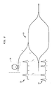
- FIG. 8 is a schematic representation of an all-optical time demultiplexer having on-chip synchronization.
- a high-speed optical signal S I received from a multiplexer (not shown) is input to the switch 110 or demultiplexer.
- the input signal S I contains a plurality of pulses (e.g., at 125) traveling at high speed which may correspond to information received from a number of different sources.
- a control signal "C” also is input to the switch 110 containing a plurality of signal pulses 135.
- the control signals must overlap in time or in other words, be synchronized with the input signal, so that they arrive within the switch at the same time, e.g., as seen on FIG. 8, two pulses of control signal 135 are synchronized with pulses of input signal 125 following dashed lines T S .
- the inventive all-pass optical filter 130 may be incorporated on the control line to delay the timing of the control signal so that it will be synchronized in time with pulses of the input signal S I.
- the single-stage all-pass optical filter is advantageous as it is less complicated than other devices, such as multiple-stage all pass optical filters, achieves a constant time delay over a wide range of frequencies, affects only the phase of the signal, not the amplitude, and can be integrated on the same chip as the switch. Thus, it is useful in achieving high-speed integrated opto-electronic devices.
Landscapes
- Physics & Mathematics (AREA)
- Engineering & Computer Science (AREA)
- Computer Networks & Wireless Communication (AREA)
- Signal Processing (AREA)
- Optics & Photonics (AREA)
- Electromagnetism (AREA)
- General Physics & Mathematics (AREA)
- Optical Communication System (AREA)
- Optical Modulation, Optical Deflection, Nonlinear Optics, Optical Demodulation, Optical Logic Elements (AREA)
- Optical Filters (AREA)
Abstract
Description
- The present invention relates to optical communications systems and more particularly, to an article comprising a single-stage all-pass optical filter.
- Optical communications systems typically include a variety of devices (e.g., light sources, photodetectors, switches, optical fibers, amplifiers, filters, and so forth). Optical communications systems are useful for transmitting optical signals over long distances at high speeds. An optical signal, which comprises a series of light pulses, is transmitted from a light source such as a laser to an optical fiber and ultimately to a detector. Amplifiers and filters may be used to propagate the light pulses along the length of the fiber from the light source to the detector. Today, the bulk of long-distance communication traffic is carried by optical fibers. As use of optical fibers becomes more widespread and infiltrates the consumer marketplace, demand is increasing for efficient, high-speed, integrated opto-electronic devices.
- There are many considerations and design constraints in developing optical systems. One consideration relates to signal synchronization in a wavelength division multiplexer or demultiplexer and/or optical time-division multiplexer (OTDM) device. Optical communications systems may include such devices for coupling, splitting, or filtering co-propagating pump signals. For example, FIG. 1 reflects a schematic representation of an OTDM system, comprising a time-division multiplexer (TDM) 100 which includes a plurality of low-
speed transmitters multiplexer 105, an optical switch ordemultiplexer 110, and areceiver 115, connected bytrunk fiber 11. Each of the transmitters sends low speed signals (sL) to themultiplexer 105 which then outputs a high speed signal (sH) to theswitch 110. The switch selectively drops pulses from the high-speed signal to produce low-speed output signals (sO) sent toreceiver 115. In this way, the signals may be sent at high-speed over the length of the fiber between themultiplexer 105 and theswitch 110, and then interpreted at low speed to determine the information sent from each one of the transmitters. - Such OTDM communication systems require synchronization elements. For example, when the
optical switch 110 demultiplexes a high bit-rate signal, a low bit-rate control "C" needs to be synchronized with the high bit-rate signal so that the signals coincide correctly in time inside the switch. This operation requires a delay line, e.g., the control will need to be delayed so it is synchronized inside the switch with the high bit-rate signal. A challenge in designing optical switches involves achieving a delay for a pulse train so that each of the frequencies of the pulse train is delayed for the same period of time. For example, FIG. 2 is a graphical illustration showing the spectrum of an unmodulated pulse train. In FIG. 2, anoptical pulse 10 typically comprises a packet ofwaves f, e.g., each wave within the packet is characterized by a different frequency and amplitude and travels at a different speed. Challenges are involved in achieving a constant time delay for each of the frequencies over the entire bandwidth f. If certain frequencies of the pulse train (e.g. 15a, 15b), are not delayed or are given a different period of delay than other frequencies (e.g., 15c, 15d), the delayed signal will not correspond in phase with the original pulse train.

- All-pass filters have been known in the field of electronics for equalizing phase and reducing distortion. Structures for fabricating all-pass filters for electronic devices are known in the field and described in the literature. See, e.g., U.S. Pat. No. 5,258,716 to Kondo et al., "All-Pass Filter." All-pass filters provide advantages over other types of filters as they affect only the phase of a signal, rather than its amplitude. A configuration for an all-pass filter for use with optical devices is described in EP-A-0 997 751; filed by Kazarinov et al.
- As explained in the Kazarinov et al. application (and shown in FIG. 2B thereof), an optical signal transmitted through a fiber may be distorted or broadened with time over the length of the fiber. This broadening is undesirable as it may create noise, i.e., interference between sequential optical pulses. The Kazarinov et al. application describes an all-pass optical filter designed to eliminate such distortions. Additionally, it was disclosed therein that the all-pass optical filter could be useful in delaying an optical pulse in time. The all-pass optical filter of the Kazarinov et al. application applies a frequency-dependent time delay to each frequency of the optical pulse.
- The Kazarinov et al. application describes single-stage and multiple-stage all-pass optical filters. A schematic representation of one embodiment a single-stage all-pass optical filter according to the Kazarinov et al. application is illustrated in FIG. 3. The filter comprises an input port for an input
optical pulse 120, anoutput port 150, a splitter/combiner 143, and afeedback path 145 wherein the feedback path advantageously comprises at least one ring resonator. Although FIG. 3 shows a single-stage filter (e.g., a single resonator ring), the Kazarinov et al. application discloses that best results are achieved when multiple stages (multiple resonator rings) are used. Indeed, the Kazarinov et al. application teaches that many all-pass stages are needed to generate a large tunable delay for an arbitrary broadband signal. For example, FIG. 4 is a graph of the group delay in units of time as a function of frequency for a four-stage all pass optical filter as applied to an arbitrary broadband signal. As can be seen, a maximum and fairly constant delay of 16 au (arbitrary units) is achieved over the normalized frequency range of 0.4 to 0.6. Thus, only certain frequencies would receive the maximum delay. A single all-pass optical filter would achieve a constant delay over a much smaller frequency range (∼05) and thus would be ineffective in delaying a pulse train having a large bandwidth (Δf). On the other hand, many all-pass stages would increase the bandwidth (Δf) of the maximum delay period and also lessen the ripple effect. As can be seen, with the four-stage all pass optical filter, a ripple effect is created over the delay period in that four separate summits appear at the maximum height of the delay peak. - However, use of many all-pass stages translates to more complicated systems than if a single-stage all pass filter were used. Preferably, two heaters are deposited on each resonator ring of the device for locally changing the free-spectral range of the group delay and the desired phase. Thus, the four-stage all-pass optical filter used to produce the delay peak shown in FIG. 4 would include the use of eight heaters, each of which would be need to be periodically adjusted depending on the optical signal and desired phase response.
- As may be appreciated, those in the field of communications systems continue to seek new designs to improve system performance and reduce cost. In particular, it would be advantageous to have an article comprising a single-stage all-pass optical filter for correcting dispersion and introducing a constant delay. It would be particularly beneficial to provide an all-pass optical filter that can generate a large tunable delay for a broadband signal without use of many all-pass stages.
- Summarily described, the invention embraces an article comprising a single-stage all-pass optical filter. The all-pass optical filter includes an input port for receiving an input optical pulse having a regular repetition rate; an output port; a splitter/combiner; and one feedback path. The all-pass optical filter is configured to apply a plurality of frequency-dependent time delay periods to the input optical pulse so that the filter is characterized by a time-delay spectrum having a plurality of delay peaks. The free-spectral range (FSR) of the filter, i.e., the spacing between the delay peaks, is matched to the regular repetition rate of the input optical pulse. This matching is accomplished by the FSR being equal to the repetition rate or offset from the repetition rate to a sufficiently small degree that each frequency of the pulse train will fall within the bandwidth of one of the plurality of delay peaks. Advantageously at least one heater is disposed on the feedback path for use in tuning the time-delay spectrum of the filter. The article including the single-stage all-pass optical filter may comprise an assembly for use in a communications system including an OTDM device or a pulsed laser.
- For a better understanding of the invention, an exemplary embodiment is described below, considered together with the accompanying drawings, in which:
- FIG. 1 is a schematic representation of an optical time-division multiplexer/ demultiplexer system;
- FIG. 2 is a graphical illustration showing an optical pulse comprising various frequencies and the repetition rate for each frequency;
- FIG. 3 is a schematic representation of a single-stage all-pass optical filter wherein the feedback path includes a ring resonator;
- FIG. 4 is a graph illustrating the normalized group delay as a function of frequency for a four-stage all-pass optical filter as applied to an arbitrary broadband signal;
- FIG. 5 is a graph illustrating the normalized group delay as a function of frequency for one embodiment of the inventive all-pass optical filter where the FSR is equal to the repetition rate of the input pulse train;
- FIG. 6 is a graph illustrating the normalized group delay as a function of frequency for an alternative embodiment of the inventive all-pass optical filter where the FSR is slightly offset from the repetition rate of the input pulse train;
- FIGS. 7A-7B are schematic illustrations of single-stage all-pass optical filters with a Mach-Zehnder interferometer structure; and
- FIG. 8 is a schematic illustration of an all-optical time DEMUX having on-chip synchronization.
-
- It is to be understood that these drawings are for the purposes of illustrating the concepts of the invention and are not to scale.
- The invention comprises a single stage all-pass optical filter that can be used to generate a large tunable delay for a regular unmodulated pulse train. Applicants have discovered that when the pulse train for a signal has a regular repetition rate (i.e., each of the frequencies of the pulse train differs from another frequency of the pulse train by an equal amount), a single-stage all-pass optical filter can be used to generate a large tunable delay for the signal. Additionally, applicants have discovered that when the repetition rate is regular, as defined above, a single-stage all-pass optical filter can be effective in correcting certain dispersion such as the linear chirp of a pulsed laser. These functions are accomplished by configuring the all-pass optical filter so that the free spectral range (FSR) of the filter, i.e., the spacing between the frequency-dependent time delay peaks generated by the filter, is matched to the repetition rate of the regular unmodulated pulse train input to the filter. By "matched to" it is meant that FSR is either equal to the repetition rate or is off-set from the repetition rate by a sufficiently small degree that each frequency of the pulse train will fall within the bandwidth of a peak of the normalized group delay.
- More particularly with reference to the figures, one embodiment of the all-pass optical filter of this invention is schematically represented by the structure of FIG. 3. This all-pass
optical filter 130 includes afeedback path 145, aninput port 140 for receivingoptical pulse 120, anoutput port 150, and a splitter/combiner 143 for coupling portions of the input optical pulse into and away from thefeedback path 145. The feedback path of the all-pass optical filter may have a ring resonator structure, as schematically shown. According to the invention, only one ring resonator structure is used and yet a large tunable delay or chirp correction is achieved, thus providing advantages over the filter of the Kazarinov et al. application. Aheating element 185 is advantageously disposed on the ring. - According to the invention, the
optical pulse 120 that enters the all-pass optical filter comprises a regular unmodulated pulse train. By defining the pulse train as "regular" herein, it is meant that the pulse train has a regular repetition rate as illustrated in FIG. 2 and described above, i.e., each of the frequencies of the pulse train differ from another (i.e., adjacent) frequency of the pulse train by the same amount which is represented in FIG. 2 as value "R." When this optical pulse enters the all-pass optical filter, a portion of the pulse is provided to thefeedback path 145 and circulates therein. At each pass of the optical pulse in thefeedback path 145, some portion thereof is provided through the splitter/combiner 143 to theoutput port 150, which incrementally reduces the portion of the optical pulse introduced into thefeedback path 145, in effect removing it therefrom. The length of thefeedback path 145 is typically shorter than the optical pulse length. Thus, as the inputoptical pulse 120 repeatedly circulates along thefeedback path 145, it interferes with itself. That is, leading edge portions of the optical signal circulating in the feedback path interfere with trailing edge portions of the optical signal being input thereto. Interference between the leading and trailing edges of the optical pulse applies a frequency-dependent time delay to the frequencies of the optical pulse. After the frequency-dependent time delays are applied to each frequency of the optical pulse, the pulse is output from the filter through theoutput port 150. - The time delay applied by the filter can be determined by the filter design and adjusted with the application of heat to the
feedback path 145. Thus, at least oneheater 185 advantageously is coupled to the feedback path, as shown. Coupling ratios for the splitter/combiner 143 andfeedback path 145 determine the portions of theoptical pulse 120 that are coupled into and away from the feedback path and thus impact upon the value for the frequency-dependent time delay that is applied. The coupling coefficient κ for the ring determines the height and width of each time-delay peak, and the phase for the ring determines the value of the FSR between each delay peak. Thus, the height and width of each delay peak is determined by the coupling coefficient κ which is configured into the device design. To illustrate, FIG. 5 is a graph of the normalized group delay as a function of frequency for five consecutive FSR's of the single-stage all-pass optical filter. As can be seen, the filter has a time delay spectrum consisting of five peaks spaced from each other by the FSR. The value for the FSR can be determined depending on the phase of the resonator ring, and the height "h" and width "w" of each delay peak can be determined depending on the coupling coefficient κ. Additionally, heat may be applied to adjust the values for κ and as would be suitable for the particular signal being input to the all-pass optical filter. Considerations involved in designing κ and are described in the Kazarinov et al. application incorporated herein and can be determined by one skilled in the field depending on the particular input signal and desired delay period. - According to one embodiment of the invention, an all-pass optical filter is configured having a time delay spectrum where the FSR of the delay peaks (FIG. 5) is equal to the repetition rate "R" of the input pulse (e.g., FIG. 2). When the FSR is equal to the repetition rate of the optical pulse rather than the full bandwidth of the signal, each frequency of the pulse train is delayed for the same maximum amount, e.g., each frequency is delayed for the period of time represented by the maximum height "h" of each delay peak of FIG. 5. Consequently, the entire signal is delayed for the same time period.
- In an alternative embodiment, the FSR is slightly offset from the repetition rate of the input pulse train. For example, FIG. 6 shows the frequencies of a pulse train denoted by
arrows 15a', 15b', 15c'... 15g', superimposed on a plot of the filter's time delay spectrum. Here, as can be seen the value for the FSR is denoted as reflecting an arbitrary unit of 1, and the value for the repetition rate "R" is slightly less than 1. Consequently, the first frequency of thepulse train 15a' will experience the maximum peak delay and each frequency thereafter experiences a slightly different (in this case lesser) delay. When the differences in the delay periods follow a linear path, the device can correct for linear chirp on the pulse train. This embodiment thus may be used inside a laser cavity as a dispersion-compensating element. Certain lasers, such as pulsed lasers, have a regular repetition rate and suffer from chirp. Such lasers would be particularly well-suited for use with the single-stage all-pass optical filter of this invention, as the filter can function to equalize the chirped pulses. In each case the degree to which the repetition rate is offset from the FSR will depend upon the phase of the pulse train, the extent of chirp sought to be corrected, and how much dispersion is sought to be generated. However, typically the repetition rate will be offset from the FSR by an amount of about 10% of the value for the FSR. - Preferably, the feedback path of the all-pass optical filter is arranged in parallel with a Mach-Zehnder interferometer (MZI), as shown in FIGS. 7A and 7B. The MZI is denoted schematically within boxed
region 300. In this embodiment, twoheaters waveguide arms heater 185 may be used to adjust the coupling coefficient K and theother heater 305 may be used to adjust the phase of the device. The MZI structure has more than one coupler, denoted as 308, 308, which optionally may be identical. The MZI structures are folded to minimize any increase in the feedback path length. In FIG. 7A, the path lengths of thewaveguide arms arm - A signal having the regular pulse train and repetition rate, as illustrated in FIG. 2, is not particularly advantageous in itself for transmitting information in an optical communications system. However, applicants have discovered that the inventive single-stage all-pass optical filter as used with a signal having a regular repetition rate is advantageous in synchronizing control signals in an optical time-division multiplexer/demultiplexer system. To illustrate, FIG. 8 is a schematic representation of an all-optical time demultiplexer having on-chip synchronization. A high-speed optical signal SI received from a multiplexer (not shown) is input to the
switch 110 or demultiplexer. The input signal SI contains a plurality of pulses (e.g., at 125) traveling at high speed which may correspond to information received from a number of different sources. A control signal "C" also is input to theswitch 110 containing a plurality ofsignal pulses 135. For the control signal "C" to operate to remove select pulses from the input signal SI, the control signals must overlap in time or in other words, be synchronized with the input signal, so that they arrive within the switch at the same time, e.g., as seen on FIG. 8, two pulses ofcontrol signal 135 are synchronized with pulses ofinput signal 125 following dashed lines TS. The inventive all-passoptical filter 130 may be incorporated on the control line to delay the timing of the control signal so that it will be synchronized in time with pulses of the input signal SI. The single-stage all-pass optical filter is advantageous as it is less complicated than other devices, such as multiple-stage all pass optical filters, achieves a constant time delay over a wide range of frequencies, affects only the phase of the signal, not the amplitude, and can be integrated on the same chip as the switch. Thus, it is useful in achieving high-speed integrated opto-electronic devices. - It is understood that the embodiments described herein are merely exemplary and that a person skilled in the art may make variations and modifications without departing from the spirit and scope of the invention. For example, although the single-stage all-pass optical filter is described primarily with regard to its applications in correcting linear chirp of a pulsed laser and delaying a control signal of an OTDM system, other applications may be recognized by one skilled in the field.
Claims (15)
- An article comprising an all-pass optical filter includingan input port for receiving an input optical pulse having a regular repetition rate;an output port;a splitter/combiner; andone feedback path, wherein the all-pass optical filter is configured to apply a plurality of frequency-dependent time delay periods to the input optical pulse to define a time delay spectrum having a plurality of delay peaks, and the free spectral range of the filter as defined by the spacing between the delay peaks is matched to the regular repetition rate of the input optical pulse.
- The all-pass optical filter of claim 1 in which the one feedback path comprises a ring resonator and a heating element for heating a section of the ring resonator.
- The all-pass optical filter of claim 1 arranged in parallel with a Mach-Zehnder interferometer.
- The all-pass optical filter of claim 1 in which the free-spectral range of the filter is matched to the repetition rate of the pulse train by the free-spectral range being equal to the repetition rate.
- An assembly for use in an optical communication system comprising an optical multiplexer/demultiplexer device including the all-pass optical filter of claim 4.
- The all-pass optical filter of claim 1, in which the free-spectral range of the filter is matched to the repetition rate of the pulse train by the free-spectral range being offset from the repetition rate by a sufficiently small degree that each frequency of the pulse train falls within a bandwidth of one of the plurality of delay peaks.
- An assembly for use in an optical communication system comprising a pulsed laser and the all-pass optical filter of claim 6, in which the all-pass optical filter corrects linear chirp of the pulsed laser.
- An optical communications system comprising the all-pass optical filter of claim 1.
- An optical communications system comprising the assembly of claim 5.
- An optical communications system comprising the assembly of claim 7.
- A method of generating a tunable delay for an optical signal with use of a single-stage all-pass optical filter wherein the pulse train of the optical signal has a regular repetition rate, the method comprising matching the spacing between the frequency-dependent time delay peaks generated by the all-pass optical filter to the repetition rate of the pulse train.
- The method of claim 11, in which the free-spectral range of the filter is matched to the repetition rate of the pulse train by the free-spectral range being equal to the repetition rate.
- The method of claim 11, in which the free-spectral range of the filter is matched to the repetition rate of the pulse train by the free-spectral range being offset from the repetition rate by a sufficiently small degree that each frequency of the pulse train falls within a bandwidth of one of the plurality of delay peaks.
- A method for correcting linear chirp of a pulsed laser comprising the steps of:providing an all-pass optical filter including an input port for receiving an input optical pulse having a regular repetition rate; an output port; a splitter/combiner; and one feedback path, wherein the all-pass optical filter is configured to apply a plurality of frequency-dependent time delay periods to the input optical pulse to define a time delay spectrum having a plurality of delay peaks, andoff-setting the free spectral range of the filter as defined by the spacing between the delay peaks from the regular repetition rate of the input optical pulse by a predetermined value such that each frequency of the pulse train falls within a bandwidth of one of the plurality of delay peaks, wherein the predetermined value is selected to substantially equalize the linear chirp of the pulsed laser.
- A method for synchronizing control signals with transmission signals of an optical time-division multiplexer/demultiplexer system, the method comprisingproviding an all-pass optical filter including an input port for receiving an input optical pulse having a regular repetition rate; an output port; a splitter/combiner; and one feedback path, wherein the all-pass optical filter is configured to apply a plurality of frequency-dependent time delay periods to the input optical pulse to define a time delay spectrum having a plurality of delay peaks,configuring the free spectral range of the all-pass optical filter as defined by the spacing between the delay peaks to be equal to the regular repetition rate of the input optical pulse, andapplying the all-pass optical filter to the control signals to delay the control signals, thereby synchronizing the control signals with the transmission signals.
Applications Claiming Priority (2)
| Application Number | Priority Date | Filing Date | Title |
|---|---|---|---|
| US493710 | 2000-01-28 | ||
| US09/493,710 US7016615B1 (en) | 2000-01-28 | 2000-01-28 | System comprising a single-stage all-pass optical filter |
Publications (2)
| Publication Number | Publication Date |
|---|---|
| EP1120926A1 true EP1120926A1 (en) | 2001-08-01 |
| EP1120926B1 EP1120926B1 (en) | 2003-10-15 |
Family
ID=23961379
Family Applications (1)
| Application Number | Title | Priority Date | Filing Date |
|---|---|---|---|
| EP01300309A Expired - Lifetime EP1120926B1 (en) | 2000-01-28 | 2001-01-15 | Article comprising a single-stage all-pass optical filter |
Country Status (4)
| Country | Link |
|---|---|
| US (1) | US7016615B1 (en) |
| EP (1) | EP1120926B1 (en) |
| JP (1) | JP4578692B2 (en) |
| DE (1) | DE60100957T2 (en) |
Cited By (1)
| Publication number | Priority date | Publication date | Assignee | Title |
|---|---|---|---|---|
| WO2003034629A1 (en) * | 2001-10-06 | 2003-04-24 | Fraunhofer-Gesellschaft zur Förderung der angewandten Forschung e.V. | Method for demultiplexing an optical data flow |
Families Citing this family (7)
| Publication number | Priority date | Publication date | Assignee | Title |
|---|---|---|---|---|
| JP2003315752A (en) | 2002-04-24 | 2003-11-06 | Fujitsu Ltd | Chromatic dispersion compensation filter |
| JP2005532558A (en) * | 2002-07-11 | 2005-10-27 | アジレント・テクノロジーズ・インク | Delay interferometer |
| CA2499651A1 (en) * | 2005-03-04 | 2006-09-04 | Itf Technologies Optiques Inc./Itf Optical Technologies Inc. | All-fiber phase controlled delay interferometer and method of making the same |
| US8073333B2 (en) * | 2007-11-16 | 2011-12-06 | Alcatel Lucent | Multiplex delay unit |
| US7945165B2 (en) * | 2007-11-16 | 2011-05-17 | Alcatel-Lucent Usa Inc. | Optical signal synchronizer |
| US7945172B2 (en) * | 2008-05-20 | 2011-05-17 | Harmonic, Inc. | Dispersion compensation circuitry and system for analog video transmission with direct modulated laser |
| US8260142B2 (en) * | 2009-06-29 | 2012-09-04 | Alcatel Lucent | Multi-channel optical arrayed time buffer |
Family Cites Families (6)
| Publication number | Priority date | Publication date | Assignee | Title |
|---|---|---|---|---|
| JP2573081Y2 (en) | 1991-07-19 | 1998-05-28 | 東光株式会社 | All-pass filter |
| JP2727883B2 (en) | 1992-08-20 | 1998-03-18 | ヤマハ株式会社 | Music synthesizer |
| US5329393A (en) | 1992-10-15 | 1994-07-12 | At&T Bell Laboratories | Optical Nyquist rate multiplexer and demultiplexer |
| US5557468A (en) * | 1995-05-16 | 1996-09-17 | Jds Fitel Inc | Chromatic dispersion compensation device |
| US6289151B1 (en) * | 1998-10-30 | 2001-09-11 | Lucent Technologies Inc. | All-pass optical filters |
| GB0210899D0 (en) * | 2002-05-13 | 2002-06-19 | Aston Photonic Tech Ltd | Dispersion compensator |
-
2000
- 2000-01-28 US US09/493,710 patent/US7016615B1/en not_active Expired - Lifetime
-
2001
- 2001-01-15 DE DE60100957T patent/DE60100957T2/en not_active Expired - Lifetime
- 2001-01-15 EP EP01300309A patent/EP1120926B1/en not_active Expired - Lifetime
- 2001-01-29 JP JP2001019944A patent/JP4578692B2/en not_active Expired - Fee Related
Non-Patent Citations (4)
| Title |
|---|
| CIMINI L J ET AL: "OPTICAL EQUALIZATION TO COMBAT THE EFFECTS OF LASER CHIRP AND FIBERDISPERSION", JOURNAL OF LIGHTWAVE TECHNOLOGY,US,IEEE. NEW YORK, vol. 8, no. 5, 1 May 1990 (1990-05-01), pages 649 - 659, XP000125357, ISSN: 0733-8724 * |
| HARVEY G T ET AL: "HARMONICALLY MODE-LOCKED FIBER RING LASER WITH AN INTERNAL FABRY-PEROT STABILIZER FOR SOLITON TRANSMISSION", OPTICS LETTERS,US,OPTICAL SOCIETY OF AMERICA, WASHINGTON, vol. 18, no. 2, 15 January 1993 (1993-01-15), pages 107 - 109, XP000331296, ISSN: 0146-9592 * |
| LENZ G ET AL: "GENERAL OPTICAL ALL-PASS FILTER STRUCTURES FOR DISPERSION CONTROL IN WDM SYSTEMS", JOURNAL OF LIGHTWAVE TECHNOLOGY,IEEE. NEW YORK,US, vol. 17, no. 7, July 1999 (1999-07-01), pages 1248 - 1254, XP000898388, ISSN: 0733-8724 * |
| MADSEN C K ET AL: "OPTICAL ALL-PASS FILTERS FOR PHASE RESPONSE DESIGN WITH APPLICATIONS FOR DISPERSION COMPENSATION", IEEE PHOTONICS TECHNOLOGY LETTERS,US,IEEE INC. NEW YORK, vol. 10, no. 7, 1 July 1998 (1998-07-01), pages 994 - 996, XP000771736, ISSN: 1041-1135 * |
Cited By (1)
| Publication number | Priority date | Publication date | Assignee | Title |
|---|---|---|---|---|
| WO2003034629A1 (en) * | 2001-10-06 | 2003-04-24 | Fraunhofer-Gesellschaft zur Förderung der angewandten Forschung e.V. | Method for demultiplexing an optical data flow |
Also Published As
| Publication number | Publication date |
|---|---|
| DE60100957D1 (en) | 2003-11-20 |
| JP2001305497A (en) | 2001-10-31 |
| EP1120926B1 (en) | 2003-10-15 |
| US7016615B1 (en) | 2006-03-21 |
| DE60100957T2 (en) | 2004-09-02 |
| JP4578692B2 (en) | 2010-11-10 |
Similar Documents
| Publication | Publication Date | Title |
|---|---|---|
| EP0997751A2 (en) | All-pass optical filter | |
| US6768874B1 (en) | Chromatic dispersion compensation device | |
| US6229633B1 (en) | Optical sampling by modulating a pulse train | |
| US6907167B2 (en) | Optical interleaving with enhanced spectral response and reduced polarization sensitivity | |
| US6396607B1 (en) | Multi-wavelength all-optical regenerators (MARS) | |
| US6141130A (en) | Spectral equalizer for multiplexed channels | |
| US8064768B2 (en) | Intra-channel equalizing optical interleaver | |
| EP1120926B1 (en) | Article comprising a single-stage all-pass optical filter | |
| CA2389937A1 (en) | Multi-pass configurations | |
| US6404526B2 (en) | WDM system that uses nonlinear temporal gratings | |
| JPH08204637A (en) | Soliton transmission system with plurality of slide frequency waveguide filter group | |
| CA2305144A1 (en) | Nonlinear optical loop mirror with adiabatic pulse compression | |
| US6384945B1 (en) | Nonlinear temporal grating as a new optical solitary wave | |
| JP2002303805A (en) | Variable dispersion compensator and optical transmission system | |
| CA2222666C (en) | Optical sampling by modulating a pulse train | |
| US20090016738A1 (en) | Compact all-optical clock recovery device | |
| JP3183605B2 (en) | WDM optical soliton transmission system | |
| JPH08286218A (en) | WDM optical soliton repeater transmission device | |
| JP2001077755A (en) | Method and apparatus for passively compressing optical pulses in an optical transmission system | |
| US6160650A (en) | Optical regeneration for wavelength-division multiplex soliton signal fiber optic transmission systems | |
| US6580857B1 (en) | Apparatus for reshaping optical pulses | |
| Devra et al. | Dispersion compensation using raised cosine filter in optical fibers | |
| JP2002503828A (en) | Apparatus for switching and scanning a clocked optical data signal | |
| WO2003013032A1 (en) | Optical signal regeneration |
Legal Events
| Date | Code | Title | Description |
|---|---|---|---|
| PUAI | Public reference made under article 153(3) epc to a published international application that has entered the european phase |
Free format text: ORIGINAL CODE: 0009012 |
|
| AK | Designated contracting states |
Kind code of ref document: A1 Designated state(s): DE FR GB |
|
| AX | Request for extension of the european patent |
Free format text: AL;LT;LV;MK;RO;SI |
|
| 17P | Request for examination filed |
Effective date: 20020128 |
|
| AKX | Designation fees paid |
Free format text: DE FR GB |
|
| 17Q | First examination report despatched |
Effective date: 20020409 |
|
| GRAH | Despatch of communication of intention to grant a patent |
Free format text: ORIGINAL CODE: EPIDOS IGRA |
|
| GRAS | Grant fee paid |
Free format text: ORIGINAL CODE: EPIDOSNIGR3 |
|
| GRAA | (expected) grant |
Free format text: ORIGINAL CODE: 0009210 |
|
| AK | Designated contracting states |
Kind code of ref document: B1 Designated state(s): DE FR GB |
|
| REG | Reference to a national code |
Ref country code: GB Ref legal event code: FG4D |
|
| REF | Corresponds to: |
Ref document number: 60100957 Country of ref document: DE Date of ref document: 20031120 Kind code of ref document: P |
|
| ET | Fr: translation filed | ||
| PLBE | No opposition filed within time limit |
Free format text: ORIGINAL CODE: 0009261 |
|
| STAA | Information on the status of an ep patent application or granted ep patent |
Free format text: STATUS: NO OPPOSITION FILED WITHIN TIME LIMIT |
|
| 26N | No opposition filed |
Effective date: 20040716 |
|
| REG | Reference to a national code |
Ref country code: GB Ref legal event code: 732E Free format text: REGISTERED BETWEEN 20131121 AND 20131127 |
|
| REG | Reference to a national code |
Ref country code: FR Ref legal event code: CD Owner name: ALCATEL-LUCENT USA INC. Effective date: 20131122 |
|
| REG | Reference to a national code |
Ref country code: FR Ref legal event code: GC Effective date: 20140410 |
|
| REG | Reference to a national code |
Ref country code: FR Ref legal event code: RG Effective date: 20141015 |
|
| REG | Reference to a national code |
Ref country code: FR Ref legal event code: PLFP Year of fee payment: 15 |
|
| REG | Reference to a national code |
Ref country code: FR Ref legal event code: PLFP Year of fee payment: 16 |
|
| REG | Reference to a national code |
Ref country code: FR Ref legal event code: PLFP Year of fee payment: 17 |
|
| REG | Reference to a national code |
Ref country code: FR Ref legal event code: PLFP Year of fee payment: 18 |
|
| PGFP | Annual fee paid to national office [announced via postgrant information from national office to epo] |
Ref country code: FR Payment date: 20181213 Year of fee payment: 19 |
|
| PGFP | Annual fee paid to national office [announced via postgrant information from national office to epo] |
Ref country code: GB Payment date: 20190109 Year of fee payment: 19 Ref country code: DE Payment date: 20190102 Year of fee payment: 19 |
|
| REG | Reference to a national code |
Ref country code: DE Ref legal event code: R119 Ref document number: 60100957 Country of ref document: DE |
|
| GBPC | Gb: european patent ceased through non-payment of renewal fee |
Effective date: 20200115 |
|
| PG25 | Lapsed in a contracting state [announced via postgrant information from national office to epo] |
Ref country code: GB Free format text: LAPSE BECAUSE OF NON-PAYMENT OF DUE FEES Effective date: 20200115 Ref country code: FR Free format text: LAPSE BECAUSE OF NON-PAYMENT OF DUE FEES Effective date: 20200131 Ref country code: DE Free format text: LAPSE BECAUSE OF NON-PAYMENT OF DUE FEES Effective date: 20200801 |