EP1120743A2 - Method and unit for suppressing a periodic pattern - Google Patents
Method and unit for suppressing a periodic pattern Download PDFInfo
- Publication number
- EP1120743A2 EP1120743A2 EP01101077A EP01101077A EP1120743A2 EP 1120743 A2 EP1120743 A2 EP 1120743A2 EP 01101077 A EP01101077 A EP 01101077A EP 01101077 A EP01101077 A EP 01101077A EP 1120743 A2 EP1120743 A2 EP 1120743A2
- Authority
- EP
- European Patent Office
- Prior art keywords
- grid
- frequency
- image signal
- periodic
- stationary
- Prior art date
- Legal status (The legal status is an assumption and is not a legal conclusion. Google has not performed a legal analysis and makes no representation as to the accuracy of the status listed.)
- Granted
Links
Images




Classifications
-
- G—PHYSICS
- G06—COMPUTING OR CALCULATING; COUNTING
- G06T—IMAGE DATA PROCESSING OR GENERATION, IN GENERAL
- G06T5/00—Image enhancement or restoration
- G06T5/10—Image enhancement or restoration using non-spatial domain filtering
-
- A—HUMAN NECESSITIES
- A61—MEDICAL OR VETERINARY SCIENCE; HYGIENE
- A61B—DIAGNOSIS; SURGERY; IDENTIFICATION
- A61B6/00—Apparatus or devices for radiation diagnosis; Apparatus or devices for radiation diagnosis combined with radiation therapy equipment
- A61B6/52—Devices using data or image processing specially adapted for radiation diagnosis
- A61B6/5211—Devices using data or image processing specially adapted for radiation diagnosis involving processing of medical diagnostic data
- A61B6/5252—Devices using data or image processing specially adapted for radiation diagnosis involving processing of medical diagnostic data removing objects from field of view, e.g. removing patient table from a CT image
-
- G—PHYSICS
- G06—COMPUTING OR CALCULATING; COUNTING
- G06T—IMAGE DATA PROCESSING OR GENERATION, IN GENERAL
- G06T5/00—Image enhancement or restoration
- G06T5/70—Denoising; Smoothing
-
- G—PHYSICS
- G06—COMPUTING OR CALCULATING; COUNTING
- G06T—IMAGE DATA PROCESSING OR GENERATION, IN GENERAL
- G06T2207/00—Indexing scheme for image analysis or image enhancement
- G06T2207/20—Special algorithmic details
- G06T2207/20048—Transform domain processing
- G06T2207/20064—Wavelet transform [DWT]
Definitions
- Radiation recording-reproducing systems have been proposed in Japanese Unexamined Patent Publication Nos. 55 (1980) - 12429, 56 (1981) - 11395, 55 (1980) - 163472, 56(1981)-164645, 55 (1980) - 116340, etc. These systems utilize a storage-type phosphor (stimulatable phosphor), which stores part of radiation energy when irradiated with radiation, such as X-rays, etc., and emits photostimulated luminescent light according to the amount of the stored radiation energy when irradiated with excitation light such as visible light, etc.
- the radiation image of a subject such as a human body, etc., is temporarily photographed and recorded on a storage-type fluorescent sheet.
- excitation light such as laser light, etc.
- excitation light is scanned on the storage-type fluorescent sheet to obtain photostimulated luminescent light.
- the obtained photostimulated luminescent light is photoelectrically read out and converted to an electrical image signal by a reading means such as a photomultiplier, etc.
- a reading means such as a photomultiplier, etc.
- the radiation image of the subject is output as a visible image to a recording material such as a photosensitive material, etc., or to a cathode-ray tube (CRT) display unit, etc.
- CTR cathode-ray tube
- the filter employed in the method in the aforementioned publication No. 10 (1998) - 164737 suppresses and removes not only the stripe pattern of the stationary grid but also the high frequency component contained in the original image, because its response at a frequency component near a spatial frequency corresponding to the grid pitch of a stationary grid used, and its response at a high frequency component greater than that, are made zero.
- an image will be reduced in sharpness.
- the present invention has been made in view of the aforementioned circumstances. Accordingly, it is the primary object to provide a periodic-pattern suppression method and a periodic-pattern suppression unit which are capable of making a periodic pattern (such as a stripe pattern, which develops in an image because of a stationary grid, etc., and the like) inconspicuous without reducing sharpness.
- a periodic pattern such as a stripe pattern, which develops in an image because of a stationary grid, etc., and the like
- a periodic-pattern suppression method of reducing a spatial frequency component which forms a periodic pattern contained in an original image signal comprising the steps of:
- periodic pattern are intended to broadly mean patterns which develop periodically in an image.
- the periodic pattern indicates a great variety of patterns such as a stripe pattern, which occurs in an image because of a stationary grid, a moire image, which occurs in an image because of the characteristics of an imaging system in a television set, and the like.
- a periodic-pattern suppression method of reducing a spatial frequency component resulting from a stationary grid, contained in an original image signal photographed using the stationary grid comprising the steps of:
- transforming into a plurality of transformed image signals means transforming into signals to which a desired process for a desired frequency component contained in the original image signal can be applied. Particularly, in the present invention, it means transforming into signals on which a process of suppressing a frequency component, contained in the original image signal represented in a real space domain, which corresponds to the stationary grid can be applied.
- an original image signal expressed in a real space domain can be transformed into image signals expressed in a frequency domain (frequency spectra) by Fourier transformation.
- an original image signal expressed in a real space domain can be transformed into subband signals expressed in a frequency domain by multiresolution transformation (employing a wavelet transform or a Laplacian pyramid expansion).
- spatial frequency component resulting from a stationary grid includes not only the spatial frequency component of the stationary grid itself, but also includes a moire component which occurs due to the stationary grid by sampling at sampling cycles less than a Nyquist frequency or by a reducing process. This is why the expression “spatial frequency component corresponding to a grid array frequency” is employed. This expression means is intended to include not only the same spatial frequency component as the grid frequency but also the same spatial frequency component as the moire frequency related to this.
- reducing a transformed image signal of the transformed image signals which has a desired frequency range containing a spatial frequency component corresponding to at least a grid array frequency of the stationary grid means to apply a process for suppressing both a spatial frequency component corresponding to the grid frequency and a spatial frequency component near the grid frequency, and does not mean to suppress almost all high frequency components greater than a spatial frequency component corresponding to the grid frequency, as in the conventional method. That is, in the present invention, as fas as it is possible, high frequency components (e.g., a spatial frequency component corresponding to a Nyquist frequency and spatial frequency components near the Nyquist frequency) greater than a spatial frequency component corresponding to the grid frequency are not suppressed.
- high frequency components e.g., a spatial frequency component corresponding to a Nyquist frequency and spatial frequency components near the Nyquist frequency
- the expression "in only the vicinity of a grid array direction of the stationary grid” means to apply the suppressing process in the grid array direction of the stationary grid or the neighboring directions, and means not to apply the suppressing process in the directions other than that, unlike applying the suppressing process independently of the grid direction, as in the conventional method.
- the "stationary grid” used herein, as described later, may be a stationary grid which is actually used, or a stationary grid, differing in grid direction, which is to be used.
- these stationary grids are included in the "stationary grid” in the expression "in only the vicinity of a grid array direction of the stationary grid.”
- the process of suppressing a component corresponding to the grid frequency may be applied in the horizontal scanning direction and the vertical scanning direction orthogonal to each other.
- the suppressing process may be applied in almost all grid directions of a stationary grid to be used.
- a desired spatial frequency component containing a grid frequency in the vicinity of the v-axis (having a slight width in the positive and negative directions of the u-axis orthogonal to the v-axis) and in the direction of the v-axis, and a desired spatial frequency component containing a grid frequency in the vicinity of the u-axis (having a slight width in the positive and negative directions of the v-axis orthogonal to the u-axis) and in the direction of the u-axis)
- the grid length direction of one stationary grid is the same as the grid array direction of the other stationary grid, and consequently, the suppressing process is applied in both of the grid array direction and grid length direction of a stationary grid orthogonal to each other.
- Performing the suppressing process only on a stationary grid that is actually used shall mean to apply the suppressing process only in the grid array direction of a stationary grid, which is actually used, or the neighboring directions, and shall mean not to apply the suppressing process in the directions (including also the grid length direction of the stationary grid) other than that.
- a vertical stationary grid it means to suppress only a component which has a desired spatial frequency range containing a grid frequency in the vicinity of the v-axis and in the direction of the v-axis.
- the aforementioned transforming step obtains a plurality of transformed image signals by applying two-dimensional wavelet transformation to the original image signal by the use of a low-pass filter which splits a band so that its response at a frequency greater than the spatial frequency of the stationary grid becomes approximately zero.
- the aforementioned reducing step further applies a process of reducing a component less than a predetermined frequency and then performs inverse wavelet transformation, with respect to a signal of the transformed image signals which contains a spatial frequency component corresponding to the grid array frequency.
- the aforementioned reducing step reduce a component less than the predetermined frequency, by recursively and repeatedly applying one-dimensional wavelet transformation to the transformed image signal (wavelet transform coefficient signal), containing a spatial frequency component corresponding to the grid array frequency, in the grid length direction of the stationary grid by a predetermined number of times by the use of a predetermined band splitting filter, then making zero transform coefficients of a low frequency image signal of a plurality of image signals obtained by one-dimensional wavelet transformation, and applying inverse one-dimensional wavelet transformation.
- the "predetermined band splitting filter” does not always need to be a low-pass filter which splits a band so that its response at a frequency greater than the spatial frequency of a stationary grid becomes approximately zero.
- a HL component obtained by two-dimensional wavelet transformation is subjected to one-dimensional wavelet transformation in the vertical scanning direction
- an LH component obtained by two-dimensional wavelet transformation is subjected to one-dimensional wavelet transformation in the horizontal scanning direction.
- a HH component obtained by two-dimensional wavelet transformation is subjected to one-dimensional wavelet transformation in the horizontal scanning direction and is then subjected to one-dimensional wavelet transformation in the vertical scanning direction. Note that the order of the horizontal and vertical scanning directions may be reversed.
- a component less than a predetermined frequency representing the stationary grid component can also be reduced by extracting only a component representing an original image from an image signal, which contains the stationary grid component, among the image signals obtained by wavelet transformation.
- the reducing step calculates powers of a plurality of transformed image signals, judges the grid length direction of the stationary grid, based on whether or not each of the calculated powers is greater than a predetermined threshold value, and applies the process for reducing a component less than a predetermined frequency, based on the result of judgement.
- the periodic-pattern suppression method according to the present invention is not limited to a stationary grid that is actually used.
- the aforementioned reducing step may be performed by employing the transformed image signals obtained by the aforementioned two-dimensional wavelet transformation.
- the aforementioned transforming step may obtain a plurality of transformed image signals by applying one-dimensional wavelet transformation to the original image signal in the grid length direction of the stationary grid by the use of a predetermined band splitting filter.
- the aforementioned reducing step may further apply a process of reducing a component less than a predetermined frequency and then perform inverse wavelet transformation, with respect to a low frequency image signal of the transformed image signals which contains a spatial frequency component corresponding to the grid array frequency of the stationary grid.
- the above case is not limited to a stationary grid that is actually used.
- the aforementioned transforming step and the reducing step can be performed on each stationary grid to be used.
- a periodic-pattern suppression unit for reducing a spatial frequency component which forms a periodic pattern contained in an original image signal, the unit comprising the steps of:
- a periodic-pattern suppression unit for reducing a spatial frequency component resulting from a stationary grid, contained in an original image signal photographed using the stationary grid, the unit comprising:
- the stationary-grid suppressing means reduce a component less than the predetermined frequency, by recursively and repeatedly applying one-dimensional wavelet transformation to the transformed image signal, containing a spatial frequency component corresponding to the grid array frequency, in a grid array direction of the stationary grid by a predetermined number of times by the use of a predetermined band splitting filter, then making zero transform coefficients of a low frequency image signal of a plurality of image signals obtained by the one-dimensional wavelet transformation, and applying inverse one-dimensional wavelet transformation.
- the periodic-pattern suppression unit may further include stationary grid-direction judging means for calculating powers of the plurality of transformed image signals and judging the grid length direction of the stationary grid, based on whether or not each of the calculated powers is greater than a predetermined threshold value.
- the stationary grid-direction judging means applies the process for reducing a component less than a predetermined frequency, based on the judgement made by the stationary grid-direction judging means.
- the above-mentioned stationary-grid suppressing means in addition to a stationary grid which is actually used, is capable of applying the process for reducing a component less than a predetermined frequency, to each stationary grid to be used.
- the image signal transforming means obtains the plurality of transformed image signals by applying one-dimensional wavelet transformation to the original image signal in the grid length direction of the stationary grid by the use of a predetermined band splitting filter.
- the stationary-grid suppressing means further applies a process for reducing a component less than a predetermined frequency and then performs inverse wavelet transformation, with respect to a low frequency image signal of the transformed image signals which contains a spatial frequency component corresponding to the grid array frequency of the stationary grid.
- the image signal transforming means may apply the one-dimensional wavelet transformation in the grid length direction of each stationary grid to be used, and the stationary-grid suppressing means may apply the reducing process and the inverse wavelet transformation to each stationary grid to be used.
- an image signal which represents an image having a periodic pattern is converted into a plurality of transformed image signals which can be handled in a frequency domain. Also, a transformed image signal of the transformed image signals, which has a desired frequency range containing a spatial frequency component corresponding to at least a frequency of the periodic pattern in only the vicinity of an array direction of the periodic pattern, is reduced. As a result, the periodic pattern in an image can be made inconspicuous.
- an original image signal, photographed using a stationary grid, and represented in a real space domain is transformed into a plurality of image signals which can be handled in a frequency domain.
- the image signal which has a desired frequency range containing the same spatial frequency component as the grid frequency of the stationary grid in approximately the grid array direction of the stationary grid, is reduced. Therefore, a stripe pattern resulting from the stationary grid will become inconspicuous.
- the stationary grid component is removed only in the grid array direction of the stationary grid and therefore there is no possibility that the image will be deteriorated more than necessary.
- the suppressing process is applied in the grid array directions of stationary grids (which differ in grid direction) to be used, the effect of the aforementioned suppressing process can be obtained without taking into consideration the grid direction of a stationary grid which is actually used. Particularly, the effect is great when two-dimensional wavelet transformation is performed.
- an image signal is given two-dimensional wavelet transformation by the use of a low-pass filter which splits a band so that its response at a frequency greater than the spatial frequency of the stationary grid becomes approximately zero, and if, among the image signals obtained by the wavelet transformation, the image signal containing a stationary grid component is further subjected to a process of reducing a component less than a predetermined frequency, an image with a reduced stationary grid component can be restored when the original image (resolution level 0) is restored by the use of the signal in which the component less than the predetermined frequency has been reduced.
- each wavelet-transform coefficient signal will not contain the spatial frequency component of the stationary grid, even if low-resolution image signals are obtained by further applying wavelet transformation over a plurality of stages. Therefore, even if an image is restored to an intermediate resolution level without being restored to resolution level 0 when it is restored, there is no possibility that a moire pattern resulting from the stationary grid will occur in a reduced-scale image (low-resolution image), because no grid component is contained in low-resolution signals of level 1 and levels thereafter. That is, even if an image is arbitrarily enlarged or reduced, no moire pattern will occur.
- the transform coefficients of the low frequency image signal are made zero, in the case where image signals that can be handled in a frequency domain are obtained by wavelet transformation, a restored image can be made an image with only the stationary grid component suppressed, as the number of repeats is increased. Thus, an image with even higher sharpness can be obtained.
- an image signal, photographed using a stationary grid, and represented in a real space domain is subjected to one-dimensional transformation in the grid length direction of the stationary grid by the use of a predetermined band splitting filter, and if, among a plurality of image signals obtained by the wavelet transformation, the image signal on the low frequency side containing the stationary grid component is further subjected to the process of reducing a component less than a predetermined frequency, an image signal which has a desired frequency range containing a spatial frequency component resulting from the stationary grid can be reduced.
- an image with a reduced grid component can be restored regardless of resolution level at which the image is restored.
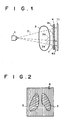
- Fig. 1 schematically shows a radiation image photographing apparatus.
- radiation 2 emitted from a radiation source 1 passes through a subject 3 and reaches a grid 4.
- lead plates 4a which absorb the radiation 2 and aluminum plates 4b which transmit the radiation 2 are alternately disposed at pitches of 4 plate/mm with a slight tilt in accordance with position so that the radiation 2 emitted from the radiation source 1 is incident straight on a recording sheet 11 via the aluminum plates 4b (refer to Fig. 1). Because of this, the radiation 2, emitted from the radiation source 1, and transmitted straight through the subject 3, is absorbed and blocked by the lead plates 4, but it is transmitted through the aluminum plates 4b and irradiated to the recording sheet 11.
- a grid image 6 with four stripes per millimeter, along with the image of the subject 3, is stored and recorded on the recording sheet 11.
- radiation 2a scattered within the subject 3 is incident obliquely with respect to the tilt of the grid 4. Since the scattered radiation 2a incident on the aluminum plates 4b is absorbed in the lead plates 4a within the grid 4, or it is reflected at the surface of the grid 4, it is not irradiated to the recording sheet 4. Thus, a distinct radiation image with less irradiation of the scattered radiation 2a is stored and recorded on the recording sheet 11.
- Fig. 2 illustrates a subject image (indicated by oblique lines) 5 and a grid image 6 in the form of a stripe pattern, stored and recorded on the recording sheet 11 by performing photographing, using the grid 4.
- a radiation image with the subject image 5 superposed on the grid image 6 is recorded on the recording sheet 11.
- Fig. 3 illustrates a radiation image reader to which an embodiment of a periodic-pattern suppression unit according to the present invention, for carrying out a periodic-pattern suppression method, is applied.
- the recording sheet 11 with the radiation image, set at a predetermined position in a reading section 10, is conveyed in a direction of arrow Y at intervals of 10 scan/mm by sheet conveying mean 10, such as an endless belt, which is driven by drive means (not shown).
- sheet conveying mean 10 such as an endless belt
- a light beam 17 emitted from a laser light source 16 is reflected and deflected by a rotating polygon mirror 18 which is driven to rotate at high speeds in an arrow-indicating direction by a motor 24.
- the deflected light beam 17 is passed through a focusing lens 19 such as f ⁇ , for example.
- the output analog signal S a is logarithmically amplified by a log amplifier 26.
- a digital image signal S carrying a high-density image with a high reading density is obtained.
- the information on the grid image 6 should be removed because it is one of the causes making it difficult to view the visible radiation image when observing it.
- the image signal S After being stored temporarily in a storage section 29, the image signal S is input to an image signal processing section 30 and processed in the following manner.
- Fig. 5 shows the image signal processing section (one form of a periodic-pattern suppression unit) 30 for carrying out the periodic-pattern suppression method of the present invention.
- the image signal processing section 30 has (1) multiresolution decomposing means 32 as image signal transforming means for applying a multiresolution decomposing process to the image signal S read out from the storage section 29, (2) processing means 33 for applying a desired process (e.g., an enhancing process) to an image signal which has a predetermined frequency band (band-limited image signal), among the band-limited image signals (band-pass and sub-band signals) decomposed to a plurality of frequency bands by the multiresolution decomposing means 32, (3) restoring means 34 for obtaining a processed image signal by restoring both the band-limited image signal, subjected to the desired process by the processing means, and the band-limited image signals carrying other frequency bands, and (4) image output means 35 for reproducing a visible image, based on the processed image signal restored by the restoring means 34.
- multiresolution decomposing means 32 as image signal transforming
- the multiresolution decomposing process employing a wavelet transform process is used when the image signal S represented in an actual spatial domain is transformed into image signals which can be handled in a frequency domain. Therefore, the multiresolution decomposing means 32 functions as wavelet transform means for applying wavelet transformation to the image signal S representing the radiation image, while the restoring means 34 functions inverse wavelet transform means for obtaining a processed image signal by applying an inverse wavelet transform process.
- the multiresolution decomposing means 32 is referred to as a wavelet transform section 32 and the restoring means 34 is referred to as an inverse wavelet transform section 34.
- the stationary grid-component suppressing means 36 is used to reduce an image signal of the image signals HL, LH, and HH which has a desired frequency range containing at least a spatial frequency component resulting from the stationary grid 4 in the grid array direction of the stationary grid 4 (i.e., a direction perpendicular to the grid direction).
- This embodiment performs two-dimensional wavelet transformation in which wavelet transform coefficients are orthogonal to one another.
- the digital image signal S read out from the storage section 29, which represents the original image
- the original image signal S ori is subjected to wavelet transformation. More specifically, a filtering process is performed in the horizontal scanning direction of the original image signal S ori (equivalent to a signal LL0) by wavelet functions H1, G1, and the pixels in the horizontal scanning direction are thinned out at every other pixel, whereby the number of pixels in the horizontal scanning direction is reduced to one half. Note that the thinned-out signals obtained in this way are represented by " ⁇ 2 " in Fig. 7.
- the function H1 is a high-pass filter, while the function G1 is a low-pass filter. Furthermore, the filtering process is performed on each of the thinned-out signals in the vertical scanning direction by the wavelet functions H1, G1, and the pixels in the vertical scanning direction are thinned out at every other pixel, whereby the number of pixels in the vertical scanning direction is reduced to one half.
- wavelet-transform coefficient signals hereinafter also referred to simply as signals
- HH1, HL1, LH1, and LL1 are obtained.
- the signal LL1 represents a one-fourth reduction image obtained by reducing the original image to one half in both the vertical and horizontal directions.
- the signal LH1 represents an image of a high frequency component (horizontal edge) in the vertical scanning direction
- the signal HL1 represents an image of a high frequency component (vertical edge) in the horizontal scanning direction
- the signal HH1 represents an image of a high frequency component (diagonal edge) in the diagonal direction
- the signal LL1 represents an image of a low frequency component of half resolution with respect to the original image.
- the frequency which becomes a reference for band split, i.e., the frequency at the boundary between the low frequency component, and each of the high frequency components is determined by the filter characteristics of the functions H1, G1.
- the function G1 as a low-pass filter has such a characteristic that its response at a spatial frequency of 4.0 cycle/mm or more is practically zero at the grid pitches of the stationary grid 4.
- the function H1 as a high-pass filter has a high-pass characteristic for compensating for the low-pass characteristic of the function G1.
- a filter with such a characteristic there is, for example, a filter having the same characteristic as a moire removing filter described in Japanese Unexamined Patent Publication No. 10 (1998) - 164737, i.e., a filter in which its response to 97% or more of the spatial frequency component at the grid pitch of the stationary grid 4 is reduced to 5% or less.
- a wavelet transform filter employing filter coefficients, such as (17, 7) - tap coefficients listed in Table 1, (13, 7)-tap coefficients listed in Table 2, and (15, 5)-tap coefficients listed in Table 3.
- filter coefficients such as (17, 7) - tap coefficients listed in Table 1, (13, 7)-tap coefficients listed in Table 2, and (15, 5)-tap coefficients listed in Table 3.
- the frequency response characteristics of the low-pass filters in wavelet transform filters are shown in Fig. 8.
- the grid component develops in the signal LH1.
- the grid component develops in the signal HL1.
- the grid component develops in the signal HH1.
- the signal LL1 a moire pattern resulting from the stationary grid 4 hardly develops regardless of grid direction, because the spatial frequency component of the stationary grid 4 has sufficiently been suppressed.
- the signals HH1, HL1, LH1, and LL1 are input to the direction judging means 35 and the grid component suppressing means 36.
- the signal LL1 is subjected to wavelet transformation by the use of basic wavelet functions H0, G0, whereby signals HH2, HL2, LH2, and LL2 are obtained.
- the signal LL2 represents a one-sixteenth reduction image obtained by reducing the original image to one-fourth in both the vertical and horizontal directions.
- the signals HL2, LH2, and HH2 represent the images of the vertical edge, horizontal edge, and diagonal edge components, respectively.
- the wavelet functions H0 and G0 which are employed at the second stage do not need to be set at the grid pitches of the stationary grid 4, unlike the wavelet functions H1 and G1 employed at the initial stage.
- the wavelet functions H0, G0 may be a wavelet transform filter employing Daubechie's (9, 7)-tap filter coefficients listed in Table 4. The frequency response characteristic of the low-pass filter in this (9, 7)-tap wavelet transform filter is shown in Fig. 8.
- a wavelet-transform coefficient signal LLk obtained for each frequency band is subjected to wavelet transformation by n times, whereby wavelet-transform coefficient signals HH1 to HHn, HL1 to HLn, LH1 to LHn, and LL1 to LLn are obtained.
- the wavelet-transform coefficient signals HHn, HLn, LHn, and LLn, obtained by the nth wavelet transformation each represent a 1/ (1/2) 2n reduction image in which the number of pixels in each of the horizontal and vertical directions is (1/2) n , compared with the original image signal S org .
- each of the wavelet-transform coefficient signals HHk, HLk, LHk, and LLk becomes a band-limited image signal carrying a frequency component which has a predetermined frequency range contained in the frequency range of the original image signal S org .
- the signal HHk represents changes in frequency in the horizontal and vertical directions of the original image signal S org , and becomes a lower frequency signal if k is greater.
- the signal HLk represents a change in frequency in the horizontal direction of the original image signal S org , and becomes a lower frequency signal if k is greater.
- the signal LHk represents a change in frequency in the vertical direction of the original image signal S org , and becomes a lower frequency signal if k is greater.
- the power of each of the signals LH1, HL1, and HH1 is calculated. Then, it is judged whether or not each power is greater than a predetermined threshold TH0. Based on the result, the grid direction of the stationary grid 4 is judged. More specifically, as described above, the grid component develops in the signal LH1 when a horizontal grid is used, develops in the signal HL1 when a vertical grid is used, and develops in the signal HH1 when a cross grid is used.
- a signal of the signals LH1, HL1, and HH1 which contains a stationary grid component is further subjected to one-dimensional wavelet transformation recursively and repeatedly by a predetermined number of times in the grid length direction of the stationary grid 4 (grid direction) by the use of a predetermined band splitting filter.
- the signal HL1 is subjected to one-dimensional wavelet transformation in the vertical scanning direction, whereby a signal HL1 (L1) , carrying a low frequency side, and a signal HL1 (H1), carrying a high frequency side, are obtained.
- the signal HL1 (L1) carrying a low frequency side is subjected to one-dimensional wavelet transformation in the vertical scanning direction, whereby a signal HL1 (L1), carrying a low frequency side, and a signal HL1 (H1), carrying a high frequency side, are obtained.
- the signal HL1 is subjected to one-dimensional wavelet transformation in the vertical scanning direction over a plurality of stages (m stages), whereby wavelet-transform coefficient signals HL1 (H1) to HL1 (Hm), HL1 (Lm) are obtained.
- Fig. 9 shows the decomposed components of the original image signal obtained after the original image signal has been subjected to wavelet transformation.
- Fig. 9A the first two-dimensional wavelet transformation is performed
- Fig. 9B after the second two-dimensional wavelet transformation the signal HL1 is subjected to one-dimensional wavelet transformation in the vertical direction once.
- the wavelet-transform coefficient signal HL1 represents a low frequency component in the vertical scanning direction and, as shown in Fig. 10, contains both a vertical grid component and an image signal which has the vertical direction of an original image signal as its main component. If the signal HL1 is subjected to one-dimensional wavelet transformation in a grid length direction (in this embodiment, vertical scanning direction), the grid component in the case of a vertical grid is considered to be a one-dimensional frequency signal which is vertically long, and therefore, band split is made so that a low frequency component containing the vertical grid component is contained in the signal HL1 (Lj) and the other high frequency components are contained in the signal HL1 (Hj).
- a low frequency signal HL1 (Lm) in which band split has sufficiently been made represents an extremely low frequency component which contains a grid component in the grid length direction independently of grid pitch size. If the "m" in the signal HL1 (Lm) becomes greater, the signal will represent only a grid component.
- the stationary grid is not perfectly placed horizontally, vertically, or in a crossing direction where "horizontal” and “vertical” are 1 : 1. Therefore, too great a number (m) of repeats will cause the grid component to develop in the signal HL1 (Hj). Thus, it is preferable that one-dimensional wavelet transformation be repeated a few times.
- a desired process e.g., an enhancing process
- the signals LLn, HLk, and LHk are sequentially subjected to inverse wavelet transformation from level n to level 1.
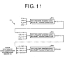
- Fig. 11 shows the construction of the inverse wavelet transform section 34.
- the inverse wavelet transform means 34a the lowest frequency band signals HHn, HLn, LHn, and LLn are subjected to inverse wavelet transformation, whereby an signal LLn-1 is obtained.
- the signal obtained by addition (referred to as a first added signal) is subjected to the aforementioned space leaving process in the horizontal scanning direction, and is subjected to the filtering process in the horizontal direction by the function G0'.
- a first signal is obtained.
- signals HLn (HLk) and HHn(HHk) are subjected to the process for leaving space for 1 pixel between adjacent pixels, in the vertical direction.
- the signals are also subjected to the filtering process in the vertical scanning direction by the inverse wavelet transform functions G0', H0', and are added.
- the signal obtained by addition (referred to as a second added signal) is subjected to the process for leaving space for 1 pixel between adjacent pixels, in the horizontal scanning direction, and is also subjected to the filtering process in the horizontal direction by the function H0'. In this way, a second signal is obtained.
- the first signal and the second signal are added, whereby a signal LLn-1(LLk-1) is obtained.
- signals HHn-1, HLn-1, and LLn-1 are subjected to inverse wavelet transformation in the same manner as the aforementioned, whereby a processed signal LLn-2 is obtained.
- a signal LL1 is obtained by repeating inverse wavelet transformation down to resolution level 1.
- the signals LL1, LH1, HH1, and HL1' are subjected to inverse wavelet transformation by the inverse wavelet transform functions G1', H1' corresponding to the functions G1, H1 employed in performing wavelet transformation at the initial stage, whereby an image is reconstructed.
- the signal HL1' has been reduced in grid component. In the reconstructed image, therefore, the grid component of the stationary grid 4 has been reduced.
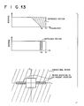
- Fig. 13 is used to explain advantages of the present invention.
- Fig. 13A illustrates a frequency response characteristic obtained in the case of a method described in Japanese Unexamined Patent Publication No. 10(1998) - 164737 (hereinafter referred to as a conventional method).
- Fig. 13B illustrates a frequency response characteristic obtained in the case of the present invention
- Fig. 13C illustrates the frequency response characteristics in Fourier space obtained by the conventional method and the method according to the present invention.
- Fig. 13C illustrates the case where a vertical stationary grid is employed in the Fourier space with the horizontal scanning direction as a v-axis and the vertical scanning direction as a u-axis.
- a filter is employed in which not only its response at a frequency near a spatial frequency corresponding to the grid pitch of a stationary grid, but also its response at a high frequency component greater than that, is made zero. Therefore, as shown in Fig. 13A, the high frequency component greater than the spatial frequency corresponding to the grid pitch is also suppressed. As a result, not only the stripe pattern of the stationary grid 4, but also the high frequency component originally contained in the image, is removed and reduced. Because of this, the image will be reduced in sharpness.
- the filtering process in the conventional method is not a filtering process taking direction into consideration, all (oblique line portion) other than a low frequency domain (central blank portion) on the Fourier space is suppressed as shown Fig. 13C. That is, not only a vertical pattern due to a vertical grid (which is desired to be really suppressed) but also a high frequency component, which is not desired to be suppressed, such as a horizontal pattern, a diagonal pattern, etc., which are contained in the original image, is suppressed.
- the predetermined range on the high frequency side is in a domain (with a slight width in a direction perpendicular to grid direction) near the grid-direction axis (in the case of a vertical grid, v-axis) of the Fourier space, and contains the spatial frequency component of the stationary grid 4.
- a high frequency component such as a horizontal pattern, a diagonal pattern, etc., which is contained in the original image, will be suppressed.
- the direction of a grid can be judged, based on the wavelet-transform coefficient signals HH1, HL1, and LH1 having a possibility of containing the grid component, among the wavelet-transform coefficient signals HH1, HL1, LH1, and LL1 obtained by two-dimensional wavelet transformation at the initial stage. Therefore, when performing the process of suppressing a grid component, there is no necessity for previously knowing what kind of grid is used in photographing.
- the restored image will contain no artifact due to the moire pattern even if it has any resolution level. As a result, a high-quality image which is easy to view can be provided.
- this embodiment is suitable for obtaining an enlarged- or reduced-scale image and is also convenient in transferring image signals through networks.
- the stationary grid 4 is a vertical grid
- the signal HL1 to be handled may be the signal LH1 or HH1, depending on the grid direction.
- the signal LH1 is further subjected to one-dimensional wavelet transformation in the horizontal scanning direction over a plurality of stages. After the signal component on the low frequency side is made zero, inverse one-dimensional wavelet transformation is applied to reconstruct the image.
- the signals HL and LH are further subjected to one-dimensional wavelet transformation in the vertical and horizontal scanning directions over a plurality of stages, respectively. After the signal component on the low frequency side is made zero, inverse one-dimensional wavelet transformation is applied to reconstruct the image.
- a high-pass filter for reducing a grid component may be employed.
- a stationary grid to be used is subjected to the aforementioned processing in each grid direction independently of the direction of a grid which is actually used, for example, and if in addition to the processing shown in Fig. 9, the signal LH1 is repeatedly subjected to one-dimensional wavelet transformation in the horizontal scanning direction, the suppressing effect can be obtained not only in a predetermined range on the high frequency side near the v-axis shown in Fig. 13C, which contains the spatial frequency component of the stationary grid 4, but also in a predetermined range on the high frequency side near the u-axis, which contains the spatial frequency component of the stationary grid 4.
- a grid of the same direction as either of horizontal and vertical scanning directions is usually employed.
- the grid component will be contained in either the signal HL (when a vertical grid is used) or signal LH1 (when a horizontal grid is used), and consequently, the effect of the aforementioned suppressing process can be obtained without considering grid direction. Also, in those cases, since the suppressing process is not applied in infinite directions but is limited only to each grid direction in which the suppressing process is to be performed, the influence of the suppressing process on an image can be reduced, compared with prior art. Note that a cross grid can be handled by repeatedly applying one-dimensional wavelet transformation to the signal HHL in both the horizontal and vertical scanning directions.
- the image signal S is subjected to two-dimensional wavelet transformation.
- the original image signal may be subjected to one-dimensional wavelet transformation in that direction (in the vertical scanning direction when the grid is a vertical grid), and the wavelet-transform coefficient signal containing a grid component (signal L1 of Fig. 14B) subjected to the process of reducing a grid component, as shown in Fig. 14.
- the wavelet function which is employed in performing one-dimensional wavelet transformation may be an arbitrary one.
- the aforementioned functions H0, G0 can be employed.
- an extremely low frequency component representing grid-length direction will develop in a low frequency wavelet-transform coefficient signal (signal L1) of the wavelet-transform coefficient signals.
- the wavelet-transform coefficient signal L1 has repeatedly been subjected to the process of reducing a grid component (e.g., one-dimensional wavelet transformation in the same direction) (see Fig. 14C)
- the lowest frequency wavelet-transform coefficient signal is made zero, or only signal components representing the original image other than the grid component are extracted with a high-pass filter. In this way, an extremely low frequency component representing the grid component can be suppressed.
- an image with a reduced grid component can be restored regardless of the resolution level at which the image is restored.
- the above-mentioned processing can also be applied in each grid direction of a stationary grid to be used, independently of the grid direction that is actually used.
- the processing is performed in the horizontal scanning direction. Between two images finally obtained, the image with fewer grid components can be used.
- the multiresolution decomposing process employing the wavelet transform process is used.
- any method of transformation can be employed as long as it can apply a process of reducing a component which has a desired frequency range containing a stationary grid component contained in an image signal.
- a multiresolution decomposing process employing a Laplacian pyramid expansion can also be employed.
- an image signal expressed in the real space domain may be transformed by Fourier transformation into image signals expressed in a frequency domain (frequency spectra).
Landscapes
- Engineering & Computer Science (AREA)
- Physics & Mathematics (AREA)
- Health & Medical Sciences (AREA)
- Life Sciences & Earth Sciences (AREA)
- Medical Informatics (AREA)
- Theoretical Computer Science (AREA)
- General Physics & Mathematics (AREA)
- Biomedical Technology (AREA)
- Animal Behavior & Ethology (AREA)
- Optics & Photonics (AREA)
- Pathology (AREA)
- Radiology & Medical Imaging (AREA)
- High Energy & Nuclear Physics (AREA)
- Heart & Thoracic Surgery (AREA)
- Molecular Biology (AREA)
- Surgery (AREA)
- Nuclear Medicine, Radiotherapy & Molecular Imaging (AREA)
- General Health & Medical Sciences (AREA)
- Public Health (AREA)
- Veterinary Medicine (AREA)
- Biophysics (AREA)
- Computer Vision & Pattern Recognition (AREA)
- Image Processing (AREA)
- Apparatus For Radiation Diagnosis (AREA)
- Facsimile Image Signal Circuits (AREA)
- Compression Or Coding Systems Of Tv Signals (AREA)
- Compression Of Band Width Or Redundancy In Fax (AREA)
Abstract
Description
| (17, 7)-tap | |
| Wavelet split low-pass filter G1 (a8, a7, a6, a5, a4, a3, a2, a1, a0, a1, a2, a3, a4, a5, a6, a7, a8) | |
| Wavelet split high-pass filter H1 (b3, b2, b1, b0, b1, b2, b3) | |
| a0 = 0.53534743 | b0 = 1.26885769 |
| a1 = 0.31296897 | b1 = -0.50000000 |
| a2 = -0.02883059 | b2 = -0.13442884 |
| a3 = -0.09095774 | b3 = -0.13442884 |
| a4 = 0.01828153 | |
| a5 = 0.03402453 | |
| a6 = -0.01037186 | |
| a7 = -0.00278855 | |
| a8 = -0.00278855 | |
| Wavelet synthesis low-pass filter G1' (-b3, b2, -b1, b0, -b1, b2, -b3) | |
| Wavelet synthesis high-pass filter H1' (a8, -a7, a6, -a5, a4, -a3, a2, -a1, a0, -a1, a2, -a3, a4, -a5, a6, -a7, a8) |
| (13, 7)-tap | |
| Wavelet split low-pass filter G1 (a6, a5, a4, a3, a2, a1, a0, a1, a2, a3, a4, a5, a6) | |
| Wavelet split high-pass filter H1 (b3, b2, b1, b0, b1, b2, b3) | |
| a0 = 0.5590000000 | b0 = 1.1678751323 |
| a1 = 0.3070000000 | b1 = -0.5408349230 |
| a2 = -0.0460000000 | b2 = -0.0839375665 |
| a3 = -0.0901544756 | b3 = 0.0408349233 |
| a4 = 0.0338214681 | |
| a5 = 0.0308330075 | |
| a6 = -0.0150000000 | |
| Wavelet synthesis low-pass filter G1' (-b3, b2, -b1, b0, -b1, b2, -b3) | |
| Wavelet synthesis high-pass filter H1' (a6, -a5, a4, -a3, a2, -a1, a0, -a1, a2, -a3, a4, -a5, a6) |
| (15, 5)-tap | |
| Wavelet split low-pass filter G1 (a7, a6, a5, a4, a3, a2, a1, a0, a1, a2, a3, a4, a5, a6, a7) | |
| Wavelet split high-pass filter H1 (b2, b1, b0, b1, b2) | |
| a0 = 0.53534743 | b0 = 1.26885769 |
| a1 = 0.31296897 | b1 = -0.50000000 |
| a2 = -0.02883059 | b2 = -0.13442884 |
| a3 = -0.09095774 | |
| a4 = 0.01828153 | |
| a5 = 0.03402453 | |
| a6 = -0.01037186 | |
| a7 = -0.00278855 | |
| Wavelet synthesis low-pass filter G1' (b2, -b1, b0, -b1, b2) | |
| Wavelet synthesis high-pass filter H1' (-a7, a6, -a5, a4, -a3, a2, -a1, a0, -a1, a2, -a3, a4, -a5, a6, -a7) |
| Daubechie's (9, 7)-tap | |
| Wavelet split low-pass filter G0 (a4, a3, a2, a1, a0, a1, a2, a3, a4) | |
| Wavelet split high-pass filter H0 (b3, b2, b1, b0, b1, b2, b3) | |
| a0 = 0.602949180 | b0 = 1.115087052000 |
| a1 = 0.266864120 | b1 = -0.591271763000 |
| a2 = -0.078223267 | b2 = -0.057543526000 |
| a3 = -0.016864118 | b3 = -0.091271763114 |
| a4 = 0.026748757 | |
| Wavelet synthesis low-pass filter G0' (-b3, b2, -b1, b0, -b1, b2, -b3) | |
| Wavelet synthesis high-pass filter H0' (a4, -a3, a2, -a1, a0, -a1, a2, -a3, a4) |
Claims (20)
- A periodic-pattern suppression method of reducing a spatial frequency component which forms a periodic pattern contained in an original image signal, said method comprising the steps of:transforming said original image signal, represented in a real space domain, into a plurality of transformed image signals which can be handled in a frequency domain; andreducing a transformed image signal of said transformed image signals which has a desired frequency range containing a spatial frequency component corresponding to at least a frequency of said periodic pattern in only the vicinity of an array direction of said periodic pattern.
- A periodic-pattern suppression method of reducing a spatial frequency component resulting from a stationary grid, contained in an original image signal photographed using said stationary grid, said method comprising the steps of:transforming said original image signal, represented in a real space domain, into a plurality of transformed image signals which can be handled in a frequency domain; andreducing a transformed image signal of said transformed image signals which has a desired frequency range containing a spatial frequency component corresponding to at least a grid array frequency of said stationary grid in only the vicinity of a grid array direction of said stationary grid.
- The periodic-pattern suppression method as set forth in claim 2, whereinsaid transforming step obtains said plurality of transformed image signals by applying two-dimensional wavelet transformation to said original image signal by the use of a low-pass filter which splits a band so that its response at a frequency greater than the spatial frequency of said stationary grid becomes approximately zero; andsaid reducing step further applies a process of reducing a component less than a predetermined frequency and then performs inverse wavelet transformation, with respect to a signal of said transformed image signals which contains a spatial frequency component corresponding to said grid array frequency.
- The periodic-pattern suppression method as set forth in claim 3, wherein said reducing step reduces a component less than said predetermined frequency, by recursively and repeatedly applying one-dimensional wavelet transformation to the transformed image signal, containing a spatial frequency component corresponding to said grid array frequency, in a grid array direction of said stationary grid by a predetermined number of times by the use of a predetermined band splitting filter, then making zero transform coefficients of a low frequency image signal of a plurality of image signals obtained by said one-dimensional wavelet transformation, and applying inverse one-dimensional wavelet transformation.
- The periodic-pattern suppression method as set forth in claim 3, wherein said reducing step calculates powers of said plurality of transformed image signals, judges the grid length direction of said stationary grid, based on whether or not each said calculated power is greater than a predetermined threshold value, and applies said process of reducing a component less than a predetermined frequency, based on the result of judgement.
- The periodic-pattern suppression method as set forth in claim 4, wherein said reducing step calculates powers of said plurality of transformed image signals, judges the grid length direction of said stationary grid, based on whether or not each said calculated power is greater than a predetermined threshold value, and applies said process of reducing a component less than a predetermined frequency, based on the result of judgement.
- The periodic-pattern suppression method as set forth in claim 3, wherein each stationary grid to be used is subjected to said reducing step.
- The periodic-pattern suppression method as set forth in claim 4, wherein each stationary grid to be used is subjected to said reducing step.
- The periodic-pattern suppression method as set forth in claim 2, whereinsaid transforming step obtains said plurality of transformed image signals by applying one-dimensional wavelet transformation to said original image signal in the grid length direction of said stationary grid by the use of a predetermined band splitting filter; andsaid reducing step further applies a process of reducing a component less than a predetermined frequency and then performs inverse wavelet transformation, with respect to a low frequency image signal of said transformed image signals which contains a spatial frequency component corresponding to the grid array frequency of said stationary grid.
- The periodic-pattern suppression method as set forth in claim 9, wherein each stationary grid to be used is subjected to said transforming step and said reducing step.
- A periodic-pattern suppression unit for reducing a spatial frequency component which forms a periodic pattern contained in an original image signal, said unit comprising the steps of:image signal transformation means for transforming said original image signal, represented in a real space domain, into a plurality of transformed image signals which can be handled in a frequency domain; andperiodic-pattern-component suppression means for reducing a transformed image signal of said transformed image signals which has a desired frequency range containing a spatial frequency component corresponding to at least a frequency of said periodic pattern in only the vicinity of an array direction of said periodic pattern.
- A periodic-pattern suppression unit for reducing a spatial frequency component resulting from a stationary grid, contained in an original image signal photographed using said stationary grid, said unit comprising:image signal transforming means for transforming said original image signal, represented in a real space domain, into a plurality of transformed image signals which can be handled in a frequency domain; andstationary grid-component suppressing means for reducing a transformed image signal of said transformed image signals which has a desired frequency range containing a spatial frequency component corresponding to at least a grid array frequency of said stationary grid in only the vicinity of a grid array direction of said stationary grid.
- The periodic-pattern suppression unit as set forth in claim 12, whereinsaid image signal transforming means obtains said plurality of transformed image signals by applying two-dimensional wavelet transformation to said original image signal by the use of a low-pass filter which splits a band so that its response at a frequency greater than the spatial frequency of said stationary grid becomes approximately zero; andsaid stationary grid-component suppressing means further applies a process of reducing a component less than a predetermined frequency and then performs inverse wavelet transformation, with respect to an image signal of said transformed image signals which contains a spatial frequency component corresponding to the grid array frequency of said stationary grid.
- The periodic-pattern suppression unit as set forth in claim 13, wherein said stationary grid-component suppressing means reduces a component less than said predetermined frequency, by recursively and repeatedly applying one-dimensional wavelet transformation to the transformed image signal, containing a spatial frequency component corresponding to said grid array frequency, in a grid array direction of said stationary grid by a predetermined number of times by the use of a predetermined band splitting filter, then making zero transform coefficients of a low frequency image signal of a plurality of image signals obtained by said one-dimensional wavelet transformation, and applying inverse one-dimensional wavelet transformation.
- The periodic-pattern suppression unit as set forth in claim 13, further comprising stationary grid-direction judging means for calculating powers of said plurality of transformed image signals and judging the grid length direction of said stationary grid, based on whether or not each said calculated power is greater than a predetermined threshold value;
wherein said stationary grid-direction judging means applies said process of reducing a component less than a predetermined frequency, based on the judgement made by said stationary grid-direction judging means. - The periodic-pattern suppression unit as set forth in claim 14, further comprising stationary grid-direction judging means for calculating powers of said plurality of transformed image signals and judging the grid length direction of said stationary grid, based on whether or not each said calculated power is greater than a predetermined threshold value;
wherein said stationary grid-direction judging means applies said process of reducing a component less than a predetermined frequency, based on the judgement made by said stationary grid-direction judging means. - The periodic-pattern suppression unit as set forth in claim 13, wherein said stationary grid-component suppressing means applies said process of reducing a component less than a predetermined frequency, to each stationary grid to be used.
- The periodic-pattern suppression unit as set forth in claim 14, wherein said stationary grid-component suppressing means applies said process of reducing a component less than a predetermined frequency, to each stationary grid to be used.
- The periodic-pattern suppression unit as set forth in claim 12, whereinsaid image signal transforming means obtains said plurality of transformed image signals by applying one-dimensional wavelet transformation to said original image signal in the grid length direction of said stationary grid by the use of a predetermined band splitting filter; andsaid stationary grid-component suppressing means further applies a process of reducing a component less than a predetermined frequency and then performs inverse wavelet transformation, with respect to a low frequency image signal of said transformed image signals which contains a spatial frequency component corresponding to the grid array frequency of said stationary grid.
- The periodic-pattern suppression unit as set forth in claim 19, whereinsaid image signal transforming means applies said one-dimensional wavelet transformation in the grid length direction of each stationary grid to be used; andsaid stationary grid-component suppressing means applies said reducing process and said inverse wavelet transformation to each said stationary grid to be used.
Applications Claiming Priority (2)
| Application Number | Priority Date | Filing Date | Title |
|---|---|---|---|
| JP2000011174 | 2000-01-20 | ||
| JP2000011174 | 2000-01-20 |
Publications (3)
| Publication Number | Publication Date |
|---|---|
| EP1120743A2 true EP1120743A2 (en) | 2001-08-01 |
| EP1120743A3 EP1120743A3 (en) | 2003-09-17 |
| EP1120743B1 EP1120743B1 (en) | 2006-07-26 |
Family
ID=18539073
Family Applications (1)
| Application Number | Title | Priority Date | Filing Date |
|---|---|---|---|
| EP20010101077 Expired - Lifetime EP1120743B1 (en) | 2000-01-20 | 2001-01-18 | Method and unit for suppressing a periodic pattern |
Country Status (3)
| Country | Link |
|---|---|
| US (1) | US7336811B2 (en) |
| EP (1) | EP1120743B1 (en) |
| DE (1) | DE60121639T2 (en) |
Cited By (2)
| Publication number | Priority date | Publication date | Assignee | Title |
|---|---|---|---|---|
| EP1372108A3 (en) * | 2002-02-08 | 2004-05-19 | Eastman Kodak Company | Method for antiscatter stationary grid artifacts detection and attenuation in digital radiographic images |
| US7433537B2 (en) | 2001-06-19 | 2008-10-07 | Fujifilm Corporation | Image reproduction system for removing noise of a periodic pattern |
Families Citing this family (24)
| Publication number | Priority date | Publication date | Assignee | Title |
|---|---|---|---|---|
| US7142705B2 (en) * | 2001-05-01 | 2006-11-28 | Canon Kabushiki Kaisha | Radiation image processing apparatus, image processing system, radiation image processing method, storage medium, and program |
| JP4267848B2 (en) * | 2001-09-25 | 2009-05-27 | 株式会社リコー | Image encoding device, image decoding device, image encoding method, and image decoding method |
| JP2003150954A (en) * | 2001-11-14 | 2003-05-23 | Fuji Photo Film Co Ltd | Cyclic pattern restraining processing method and device |
| US7826682B2 (en) * | 2005-04-14 | 2010-11-02 | Agfa Healthcare | Method of suppressing a periodical pattern in an image |
| JP2006318103A (en) * | 2005-05-11 | 2006-11-24 | Fuji Photo Film Co Ltd | Image processor, image processing method, and program |
| US7796792B2 (en) * | 2005-06-29 | 2010-09-14 | Agfa Healthcare, N.V. | Method of identifying disturbing frequencies originating from the presence of an anti-scatter grid during acquisition of a radiation image |
| US20070053603A1 (en) * | 2005-09-08 | 2007-03-08 | Monro Donald M | Low complexity bases matching pursuits data coding and decoding |
| US20070065034A1 (en) * | 2005-09-08 | 2007-03-22 | Monro Donald M | Wavelet matching pursuits coding and decoding |
| US7848584B2 (en) * | 2005-09-08 | 2010-12-07 | Monro Donald M | Reduced dimension wavelet matching pursuits coding and decoding |
| US8121848B2 (en) * | 2005-09-08 | 2012-02-21 | Pan Pacific Plasma Llc | Bases dictionary for low complexity matching pursuits data coding and decoding |
| US7813573B2 (en) | 2005-09-08 | 2010-10-12 | Monro Donald M | Data coding and decoding with replicated matching pursuits |
| EP1790991B1 (en) * | 2005-11-28 | 2011-11-16 | Kabushiki Kaisha Toshiba | Data processing system and data processing method involving a Wiener filter |
| JP2008015741A (en) * | 2006-07-05 | 2008-01-24 | Konica Minolta Holdings Inc | Image processor, image processing method, and image pickup device using the same |
| CA2724212A1 (en) * | 2008-05-15 | 2009-11-19 | Siemens Aktiengesellschaft | Sensor device |
| US7791513B2 (en) | 2008-10-06 | 2010-09-07 | Donald Martin Monro | Adaptive combinatorial coding/decoding with specified occurrences for electrical computers and digital data processing systems |
| US7786903B2 (en) * | 2008-10-06 | 2010-08-31 | Donald Martin Monro | Combinatorial coding/decoding with specified occurrences for electrical computers and digital data processing systems |
| US7864086B2 (en) * | 2008-10-06 | 2011-01-04 | Donald Martin Monro | Mode switched adaptive combinatorial coding/decoding for electrical computers and digital data processing systems |
| US7786907B2 (en) * | 2008-10-06 | 2010-08-31 | Donald Martin Monro | Combinatorial coding/decoding with specified occurrences for electrical computers and digital data processing systems |
| JPWO2011040074A1 (en) * | 2009-09-30 | 2013-02-21 | シャープ株式会社 | Image enlargement device, image enlargement program, and display device |
| US8897569B2 (en) * | 2010-03-01 | 2014-11-25 | Sharp Kabushiki Kaisha | Image enlargement device, image enlargement program, memory medium on which an image enlargement program is stored, and display device |
| US9968316B2 (en) | 2010-12-29 | 2018-05-15 | General Electric Company | High-frequency anti-scatter grid movement profile for line cancellation |
| US8867699B2 (en) * | 2011-08-31 | 2014-10-21 | Shimadzu Corporation | Radiographic device |
| JP6139897B2 (en) | 2013-02-05 | 2017-05-31 | キヤノン株式会社 | Image analysis apparatus, radiation imaging apparatus, image analysis method, program, and storage medium |
| CN111369450B (en) * | 2020-02-21 | 2024-02-02 | 华为技术有限公司 | Methods and devices for removing moiré patterns |
Family Cites Families (15)
| Publication number | Priority date | Publication date | Assignee | Title |
|---|---|---|---|---|
| JPS5512429A (en) | 1978-07-12 | 1980-01-29 | Fuji Photo Film Co Ltd | Radioactive image reader |
| US4315318A (en) | 1978-12-26 | 1982-02-09 | Fuji Photo Film Co., Ltd. | Method and apparatus for processing a radiation image |
| JPS55163472A (en) | 1978-12-26 | 1980-12-19 | Fuji Photo Film Co Ltd | Radiant ray image processing method |
| JPS55116340A (en) | 1979-02-28 | 1980-09-06 | Fuji Photo Film Co Ltd | Method and device for processing gradation of radiation picture |
| JPS5611395A (en) | 1979-07-11 | 1981-02-04 | Fuji Photo Film Co Ltd | Radiation image writeereading device |
| JPS56164645A (en) | 1980-05-21 | 1981-12-17 | Oki Electric Ind Co Ltd | Branch relaying system |
| US5028784A (en) * | 1989-04-11 | 1991-07-02 | Fuji Photo Film Co., Ltd. | Method for generating radiation image signals, image processing method, and radiation image read-out apparatus |
| US5173788A (en) * | 1990-02-07 | 1992-12-22 | Brother Kogyo Kabushiki Kaisha | Image reading device having moire depressing unit |
| FR2662283B1 (en) * | 1990-05-15 | 1992-07-24 | Thomson Trt Defense | PROCESS FOR CORRECTING IMAGES FROM SENSOR CAUSING PERIODIC NOISE, AND DEVICE FOR IMPLEMENTING SAME. |
| US5798846A (en) * | 1996-05-28 | 1998-08-25 | Hewlett-Packard Company | Apparatus and method for selectively processing a scanned image |
| JP3706201B2 (en) * | 1996-07-18 | 2005-10-12 | 富士写真フイルム株式会社 | Image processing method |
| JPH10164737A (en) | 1996-11-25 | 1998-06-19 | Mitsubishi Electric Corp | Gas insulated transmission line |
| US6333990B1 (en) * | 1998-06-02 | 2001-12-25 | General Electric Company | Fourier spectrum method to remove grid line artifacts without changing the diagnostic quality in X-ray images |
| JP2000003440A (en) * | 1998-06-12 | 2000-01-07 | Fuji Photo Film Co Ltd | Moire removing filter and image processing method and device using the filter |
| US6269176B1 (en) * | 1998-12-21 | 2001-07-31 | Eastman Kodak Company | Method for x-ray antiscatter grid detection and suppression in digital radiography |
-
2001
- 2001-01-18 EP EP20010101077 patent/EP1120743B1/en not_active Expired - Lifetime
- 2001-01-18 DE DE2001621639 patent/DE60121639T2/en not_active Expired - Lifetime
- 2001-01-22 US US09/765,621 patent/US7336811B2/en not_active Expired - Fee Related
Cited By (2)
| Publication number | Priority date | Publication date | Assignee | Title |
|---|---|---|---|---|
| US7433537B2 (en) | 2001-06-19 | 2008-10-07 | Fujifilm Corporation | Image reproduction system for removing noise of a periodic pattern |
| EP1372108A3 (en) * | 2002-02-08 | 2004-05-19 | Eastman Kodak Company | Method for antiscatter stationary grid artifacts detection and attenuation in digital radiographic images |
Also Published As
| Publication number | Publication date |
|---|---|
| US7336811B2 (en) | 2008-02-26 |
| US20010012407A1 (en) | 2001-08-09 |
| DE60121639D1 (en) | 2006-09-07 |
| EP1120743B1 (en) | 2006-07-26 |
| DE60121639T2 (en) | 2007-07-26 |
| EP1120743A3 (en) | 2003-09-17 |
Similar Documents
| Publication | Publication Date | Title |
|---|---|---|
| EP1120743B1 (en) | Method and unit for suppressing a periodic pattern | |
| EP0677780B1 (en) | Image superposition processing method | |
| DE69021365T2 (en) | HALFTONE IMAGING SYSTEM. | |
| DE69034039T2 (en) | Method for generating radiation image signals and radiation readout apparatus | |
| EP0756247B1 (en) | Image processing method and apparatus | |
| JPH06301766A (en) | Multiprocessing method for radiation picture on basis of pyramid picture decomposition | |
| JPH0696200A (en) | Noise reduction method and apparatus | |
| JPH0785247A (en) | Method for processing energy subtraction image | |
| JPH10268451A (en) | Method for recording and reading radiation image of slender object | |
| JP2754068B2 (en) | Radiation image signal generation method and radiation image reading device | |
| JP2004261514A (en) | Image processor, image processing method and program | |
| JPH0312785A (en) | Image processing method | |
| US6173086B1 (en) | Image processing method | |
| US5694447A (en) | Energy subtraction processing method and apparatus | |
| US6614044B2 (en) | Image signal generating method, apparatus and program | |
| JP4265869B2 (en) | Periodic pattern suppression processing method and apparatus | |
| JP2952418B2 (en) | Radiation image signal generation method | |
| JPH06274614A (en) | Image processing method | |
| JP2962527B2 (en) | Charge image scanning device | |
| US6587594B1 (en) | Moire eliminating filter and image processing method and apparatus using the filter | |
| JP2952451B2 (en) | Radiation image reproducing method and apparatus | |
| JPH09160149A (en) | Image processing method and device | |
| JP2001189866A (en) | Still grid suppression processing method and device | |
| EP0792061B1 (en) | Method for generating radiation image signals and radiation read-out apparatus | |
| JP4163401B2 (en) | Image signal generation method, apparatus, and program |
Legal Events
| Date | Code | Title | Description |
|---|---|---|---|
| PUAI | Public reference made under article 153(3) epc to a published international application that has entered the european phase |
Free format text: ORIGINAL CODE: 0009012 |
|
| AK | Designated contracting states |
Kind code of ref document: A2 Designated state(s): AT BE CH CY DE DK ES FI FR GB GR IE IT LI LU MC NL PT SE TR |
|
| AX | Request for extension of the european patent |
Free format text: AL;LT;LV;MK;RO;SI |
|
| PUAL | Search report despatched |
Free format text: ORIGINAL CODE: 0009013 |
|
| RIC1 | Information provided on ipc code assigned before grant |
Ipc: 7G 06T 5/10 A Ipc: 7G 06T 5/00 B |
|
| AK | Designated contracting states |
Kind code of ref document: A3 Designated state(s): AT BE CH CY DE DK ES FI FR GB GR IE IT LI LU MC NL PT SE TR |
|
| AX | Request for extension of the european patent |
Extension state: AL LT LV MK RO SI |
|
| 17P | Request for examination filed |
Effective date: 20031127 |
|
| 17Q | First examination report despatched |
Effective date: 20040219 |
|
| AKX | Designation fees paid |
Designated state(s): BE DE FR NL |
|
| GRAP | Despatch of communication of intention to grant a patent |
Free format text: ORIGINAL CODE: EPIDOSNIGR1 |
|
| GRAS | Grant fee paid |
Free format text: ORIGINAL CODE: EPIDOSNIGR3 |
|
| GRAA | (expected) grant |
Free format text: ORIGINAL CODE: 0009210 |
|
| AK | Designated contracting states |
Kind code of ref document: B1 Designated state(s): BE DE FR NL |
|
| REF | Corresponds to: |
Ref document number: 60121639 Country of ref document: DE Date of ref document: 20060907 Kind code of ref document: P |
|
| ET | Fr: translation filed | ||
| RAP2 | Party data changed (patent owner data changed or rights of a patent transferred) |
Owner name: FUJIFILM CORPORATION |
|
| NLT2 | Nl: modifications (of names), taken from the european patent patent bulletin |
Owner name: FUJIFILM CORPORATION Effective date: 20070314 |
|
| PLBE | No opposition filed within time limit |
Free format text: ORIGINAL CODE: 0009261 |
|
| STAA | Information on the status of an ep patent application or granted ep patent |
Free format text: STATUS: NO OPPOSITION FILED WITHIN TIME LIMIT |
|
| 26N | No opposition filed |
Effective date: 20070427 |
|
| REG | Reference to a national code |
Ref country code: FR Ref legal event code: TP Ref country code: FR Ref legal event code: CD |
|
| REG | Reference to a national code |
Ref country code: FR Ref legal event code: PLFP Year of fee payment: 16 |
|
| REG | Reference to a national code |
Ref country code: FR Ref legal event code: PLFP Year of fee payment: 17 |
|
| REG | Reference to a national code |
Ref country code: DE Ref legal event code: R082 Ref document number: 60121639 Country of ref document: DE Representative=s name: KLUNKER IP PATENTANWAELTE PARTG MBB, DE |
|
| REG | Reference to a national code |
Ref country code: FR Ref legal event code: PLFP Year of fee payment: 18 |
|
| PGFP | Annual fee paid to national office [announced via postgrant information from national office to epo] |
Ref country code: NL Payment date: 20181213 Year of fee payment: 19 |
|
| PGFP | Annual fee paid to national office [announced via postgrant information from national office to epo] |
Ref country code: FR Payment date: 20181212 Year of fee payment: 19 Ref country code: BE Payment date: 20181217 Year of fee payment: 19 |
|
| PGFP | Annual fee paid to national office [announced via postgrant information from national office to epo] |
Ref country code: DE Payment date: 20190108 Year of fee payment: 19 |
|
| REG | Reference to a national code |
Ref country code: DE Ref legal event code: R119 Ref document number: 60121639 Country of ref document: DE |
|
| REG | Reference to a national code |
Ref country code: NL Ref legal event code: MM Effective date: 20200201 |
|
| REG | Reference to a national code |
Ref country code: BE Ref legal event code: MM Effective date: 20200131 |
|
| PG25 | Lapsed in a contracting state [announced via postgrant information from national office to epo] |
Ref country code: NL Free format text: LAPSE BECAUSE OF NON-PAYMENT OF DUE FEES Effective date: 20200201 Ref country code: FR Free format text: LAPSE BECAUSE OF NON-PAYMENT OF DUE FEES Effective date: 20200131 Ref country code: DE Free format text: LAPSE BECAUSE OF NON-PAYMENT OF DUE FEES Effective date: 20200801 |
|
| PG25 | Lapsed in a contracting state [announced via postgrant information from national office to epo] |
Ref country code: BE Free format text: LAPSE BECAUSE OF NON-PAYMENT OF DUE FEES Effective date: 20200131 |