EP1120684A1 - Laser marking system - Google Patents
Laser marking system Download PDFInfo
- Publication number
- EP1120684A1 EP1120684A1 EP01200116A EP01200116A EP1120684A1 EP 1120684 A1 EP1120684 A1 EP 1120684A1 EP 01200116 A EP01200116 A EP 01200116A EP 01200116 A EP01200116 A EP 01200116A EP 1120684 A1 EP1120684 A1 EP 1120684A1
- Authority
- EP
- European Patent Office
- Prior art keywords
- chamber
- laser
- lens
- nozzle element
- laser energy
- Prior art date
- Legal status (The legal status is an assumption and is not a legal conclusion. Google has not performed a legal analysis and makes no representation as to the accuracy of the status listed.)
- Withdrawn
Links
- 238000010330 laser marking Methods 0.000 title claims abstract description 16
- 238000004140 cleaning Methods 0.000 claims description 7
- 239000000779 smoke Substances 0.000 claims description 5
- 239000013618 particulate matter Substances 0.000 claims description 2
- 238000000034 method Methods 0.000 description 7
- 238000004049 embossing Methods 0.000 description 5
- CURLTUGMZLYLDI-UHFFFAOYSA-N Carbon dioxide Chemical compound O=C=O CURLTUGMZLYLDI-UHFFFAOYSA-N 0.000 description 3
- 230000000694 effects Effects 0.000 description 3
- 238000005516 engineering process Methods 0.000 description 3
- VEXZGXHMUGYJMC-UHFFFAOYSA-N Hydrochloric acid Chemical compound Cl VEXZGXHMUGYJMC-UHFFFAOYSA-N 0.000 description 2
- RAHZWNYVWXNFOC-UHFFFAOYSA-N Sulphur dioxide Chemical compound O=S=O RAHZWNYVWXNFOC-UHFFFAOYSA-N 0.000 description 2
- 239000006227 byproduct Substances 0.000 description 2
- 229910002092 carbon dioxide Inorganic materials 0.000 description 2
- 238000011161 development Methods 0.000 description 2
- 230000018109 developmental process Effects 0.000 description 2
- 238000004519 manufacturing process Methods 0.000 description 2
- 239000011159 matrix material Substances 0.000 description 2
- 239000000047 product Substances 0.000 description 2
- 239000002699 waste material Substances 0.000 description 2
- PFNQVRZLDWYSCW-UHFFFAOYSA-N (fluoren-9-ylideneamino) n-naphthalen-1-ylcarbamate Chemical compound C12=CC=CC=C2C2=CC=CC=C2C1=NOC(=O)NC1=CC=CC2=CC=CC=C12 PFNQVRZLDWYSCW-UHFFFAOYSA-N 0.000 description 1
- UGFAIRIUMAVXCW-UHFFFAOYSA-N Carbon monoxide Chemical compound [O+]#[C-] UGFAIRIUMAVXCW-UHFFFAOYSA-N 0.000 description 1
- XFXPMWWXUTWYJX-UHFFFAOYSA-N Cyanide Chemical compound N#[C-] XFXPMWWXUTWYJX-UHFFFAOYSA-N 0.000 description 1
- BQCADISMDOOEFD-UHFFFAOYSA-N Silver Chemical compound [Ag] BQCADISMDOOEFD-UHFFFAOYSA-N 0.000 description 1
- 150000001299 aldehydes Chemical class 0.000 description 1
- XAGFODPZIPBFFR-UHFFFAOYSA-N aluminium Chemical compound [Al] XAGFODPZIPBFFR-UHFFFAOYSA-N 0.000 description 1
- 229910052782 aluminium Inorganic materials 0.000 description 1
- 239000001569 carbon dioxide Substances 0.000 description 1
- 229910002091 carbon monoxide Inorganic materials 0.000 description 1
- 238000004891 communication Methods 0.000 description 1
- 239000012141 concentrate Substances 0.000 description 1
- 230000001276 controlling effect Effects 0.000 description 1
- 230000000875 corresponding effect Effects 0.000 description 1
- 230000002939 deleterious effect Effects 0.000 description 1
- 238000001514 detection method Methods 0.000 description 1
- 238000000605 extraction Methods 0.000 description 1
- 238000007730 finishing process Methods 0.000 description 1
- 239000012530 fluid Substances 0.000 description 1
- 239000003517 fume Substances 0.000 description 1
- 230000003993 interaction Effects 0.000 description 1
- 238000007648 laser printing Methods 0.000 description 1
- 238000012423 maintenance Methods 0.000 description 1
- 239000000463 material Substances 0.000 description 1
- QSHDDOUJBYECFT-UHFFFAOYSA-N mercury Chemical compound [Hg] QSHDDOUJBYECFT-UHFFFAOYSA-N 0.000 description 1
- 229910052753 mercury Inorganic materials 0.000 description 1
- 239000007769 metal material Substances 0.000 description 1
- 239000012299 nitrogen atmosphere Substances 0.000 description 1
- 238000007639 printing Methods 0.000 description 1
- 238000012545 processing Methods 0.000 description 1
- 230000005855 radiation Effects 0.000 description 1
- 229910052709 silver Inorganic materials 0.000 description 1
- 239000004332 silver Substances 0.000 description 1
- 238000007619 statistical method Methods 0.000 description 1
- 238000012795 verification Methods 0.000 description 1
Images


Classifications
-
- B—PERFORMING OPERATIONS; TRANSPORTING
- B23—MACHINE TOOLS; METAL-WORKING NOT OTHERWISE PROVIDED FOR
- B23K—SOLDERING OR UNSOLDERING; WELDING; CLADDING OR PLATING BY SOLDERING OR WELDING; CUTTING BY APPLYING HEAT LOCALLY, e.g. FLAME CUTTING; WORKING BY LASER BEAM
- B23K26/00—Working by laser beam, e.g. welding, cutting or boring
- B23K26/14—Working by laser beam, e.g. welding, cutting or boring using a fluid stream, e.g. a jet of gas, in conjunction with the laser beam; Nozzles therefor
- B23K26/1462—Nozzles; Features related to nozzles
- B23K26/1464—Supply to, or discharge from, nozzles of media, e.g. gas, powder, wire
-
- G—PHYSICS
- G03—PHOTOGRAPHY; CINEMATOGRAPHY; ANALOGOUS TECHNIQUES USING WAVES OTHER THAN OPTICAL WAVES; ELECTROGRAPHY; HOLOGRAPHY
- G03B—APPARATUS OR ARRANGEMENTS FOR TAKING PHOTOGRAPHS OR FOR PROJECTING OR VIEWING THEM; APPARATUS OR ARRANGEMENTS EMPLOYING ANALOGOUS TECHNIQUES USING WAVES OTHER THAN OPTICAL WAVES; ACCESSORIES THEREFOR
- G03B17/00—Details of cameras or camera bodies; Accessories therefor
- G03B17/24—Details of cameras or camera bodies; Accessories therefor with means for separately producing marks on the film, e.g. title, time of exposure
- G03B17/245—Optical means
-
- G—PHYSICS
- G03—PHOTOGRAPHY; CINEMATOGRAPHY; ANALOGOUS TECHNIQUES USING WAVES OTHER THAN OPTICAL WAVES; ELECTROGRAPHY; HOLOGRAPHY
- G03B—APPARATUS OR ARRANGEMENTS FOR TAKING PHOTOGRAPHS OR FOR PROJECTING OR VIEWING THEM; APPARATUS OR ARRANGEMENTS EMPLOYING ANALOGOUS TECHNIQUES USING WAVES OTHER THAN OPTICAL WAVES; ACCESSORIES THEREFOR
- G03B27/00—Photographic printing apparatus
- G03B27/32—Projection printing apparatus, e.g. enlarger, copying camera
- G03B27/52—Details
- G03B27/521—Arrangements for applying a supplementary information onto the sensitive material, e.g. coding
Definitions
- the invention relates generally to the field of laser marking systems. More particularly, the invention concerns an apparatus and a method that uses laser energy for marking indicia on photosensitive web with a dramatic reduction in the occurrence of fog on the photosensitive web.
- Edge marked film has direct verification of roll identity, sheet identity and waste identity during all stages of the manufacturing process. Importantly, edge marked film provides accurate footage identification that enables operators to quickly identify, trace and remove film imperfections, thereby minimizing the amount of product waste. More generally, edge marked film increases process understanding by allowing process interactions to be more closely identified with their corresponding effect on the product.
- Traditional embossing marking techniques are being replaced by laser edge marking. Current mechanical embossing techniques (embossing wheels) are not programmable, generate poor quality marks and require excessive maintenance. Laser edge marking, on the other hand, is particularly advantageous in the industry because it provides a permanent record and can be read before and after film processing.
- variable information to be permanently marked on the edge of each sheet of photosensitive web, such as photographic film, without significant incidences of fog spots on the surface of the film.
- Yet another object of the invention is to provide a nozzle element adaptable to an apparatus for laser printing indicia on a photosensitive web by further directing a jet of air onto the laser energy impinged surface of the photosensitive web.
- the apparatus for laser marking indicia on a moving photosensitive web has a nozzle element associated with the laser beam tube for reducing fog spots on the photosensitive web.
- a nozzle element adaptable to a laser beam tube comprises:
- nozzle element 10 has a preferably generally cylindrical shaped chamber 12 with a laser energy inlet end 14 and a laser energy outlet end 16.
- Inlet end 14 is adaptable to any laser energy output device, such as a laser marking system for marking indicia on photosensitive web.
- Output end 16 is configured to focus beams of radiation onto a moving photosensitive web and to be spaced proximate to the moving photosensitive web.
- an air jet member 18 is arranged in the chamber 12 near the outlet end 16. Air to air jet member 18 may be supplied by any general source (not shown). Air jet member 18 is configured for directing a burst of air onto a laser beam impingeable surface, such as a photosensitive web positioned proximate to the air jet member 18.
- chamber 12 has at least one lens 20 arranged therein for focusing each one of a plurality of laser beams passing through the chamber 12.
- Lens 20 is preferably a short focal length zinc selenide lens.
- Lens 20 may be mounted in any one of a variety of ways in chamber 12, for instance using a typical lens mount (not shown).
- a lens cleaning member 22 is arranged in the chamber 12 proximate the lens 20.
- Nozzle element 10 was developed to keep the lens 20 clean, prevent plume and draw away vapors associated with impinging laser energy.
- lens cleaning member 22 is a positive air flow pattern surrounding the lens 20 that shields the lens 20 from particulate matter.
- lens cleaning member 22 may be a burst of air directed at the lens 20 (not shown).
- chamber 12 further has a vacuum inlet port 24 and a vacuum outlet port 26 in fluid communication with the chamber 12.
- Vacuum outlet port 26 provides means for evacuating the chamber 12 of smoke and debris generated during laser marking.
- outlet port 26 preferably has a generally conical shape. Affluence generated by the marking process without vacuum resulted in no detection of cyanide, sulfur dioxide, hydrochloric acid, or carbon monoxide. Carbon dioxide could be detected but the level was below exposure limits. Mercury, silver and aldehydes vapors were adequately removed by the Fumex FA2 fume extraction machine.
- Vacuum inlet port 24 connected to a source of vacuum (not shown), provides a means for receiving such particulates that are ejected through vacuum outlet port 26.
- nozzle element 10 adapted to a laser beam tube 30 having a plurality of lasers 32 therein.
- Laser beam tube 30 is preferably the output end of a laser marking system 34 (only partially shown).
- nozzle element 10 is made from any structurally rigid material such as any metallic material.
- any structurally rigid material such as any metallic material.
- we prefer using aluminum because it is light-weight and can be easily formed.
- nozzle element 10 is adapted to a laser beam tube 30 of a laser marking system 34.
- Laser beams generated by a plurality of lasers 32 pass through the nozzle element 10 and are focused by lens 20 in a predetermined pattern onto a photosensitive web (not shown).
- Debris, such as plume of smoke, generated by the laser energy striking the photosensitive web is drawn away from the web and into and through the chamber 12 via the vacuum inlet and outlet ports 24, 26.
- Circulating air surrounding lens 20 defining lens cleaning member 22 keeps lens 20 from accumulating particulates during laser marking. In this way, the focus of the laser beams is not distorted during operations.
Landscapes
- Physics & Mathematics (AREA)
- Optics & Photonics (AREA)
- Engineering & Computer Science (AREA)
- General Physics & Mathematics (AREA)
- Plasma & Fusion (AREA)
- Mechanical Engineering (AREA)
- Laser Beam Processing (AREA)
- Laser Beam Printer (AREA)
- Light Sources And Details Of Projection-Printing Devices (AREA)
- Exposure And Positioning Against Photoresist Photosensitive Materials (AREA)
- Dot-Matrix Printers And Others (AREA)
Abstract
A nozzle element (10) for laser marking indicia on a moving
photosensitive web substantially reduces fog spots on the web caused by
impinging laser energy. The nozzle element (10) is configured to conform to the
outlet end of the laser beam tube (30) to eject particulates through vacuum outlet
port.
Description
- The invention relates generally to the field of laser marking systems. More particularly, the invention concerns an apparatus and a method that uses laser energy for marking indicia on photosensitive web with a dramatic reduction in the occurrence of fog on the photosensitive web.
- Conventional edge marking in photographic film manufacturing involves printing some sort of identification indicia along the edge of film rolls during the finishing operation. Edge marked film has direct verification of roll identity, sheet identity and waste identity during all stages of the manufacturing process. Importantly, edge marked film provides accurate footage identification that enables operators to quickly identify, trace and remove film imperfections, thereby minimizing the amount of product waste. More generally, edge marked film increases process understanding by allowing process interactions to be more closely identified with their corresponding effect on the product. Traditional embossing marking techniques are being replaced by laser edge marking. Current mechanical embossing techniques (embossing wheels) are not programmable, generate poor quality marks and require excessive maintenance. Laser edge marking, on the other hand, is particularly advantageous in the industry because it provides a permanent record and can be read before and after film processing.
- Advances in laser technology enabled the use of a dot matrix CO2 laser marking system to be used to replace existing embossing technology. Off the shelf laser marking equipment will mark the film at required throughput rate, however, an unacceptable level of fog spots occurred.
- Thus, a particular shortcoming of these advanced high powered laser systems used for edge marking photosensitive film is that they produce a by-product that impinges on the film surface. Laser energy by-products in the form of a plume of energized smoke and irradiated debris on the film surface is known to cause the localized fogging on the film. Experience has shown that localized fogging is not easily eliminated even when the film is immersed in a 99.8% nitrogen atmosphere.
- More recent developments in laser technology enabled the development of high speed marking systems using short pulse lasers. Short pulse laser exposure on photosensitive film shows some promise in reducing the occurrences of fog spots. Our experience also indicates that an air jet directed at the laser impingement point on the film surface further reduce the occurrence of fog. Statistical methods have been employed to gain information on fog incidence reduction when laser marking photosensitive film. It has been experimentally proven that laser pulse width does not have a significant effect on fog. Importantly, however, our experience does suggest that laser peak power has a dramatic effect on the reduction of occurrences of fog spots by a factor of 30. In addition, significant statistical benefits can be derived from an air jet that we believe can further reduce the incidences of fog spots by a factor of 10.
- Hence, laser marking without controlling peak power will result in 14% to 50% of the laser-generated dots of dot matrix characters to have fog spots around the dots. There are no present attempts known to the inventors to control peak power in laser edge marking devices because embossing techniques still remain prevalent in the industry and, more importantly, the fog spots remain a significant quality issue during the finishing process.
- Therefore, a need persists for variable information to be permanently marked on the edge of each sheet of photosensitive web, such as photographic film, without significant incidences of fog spots on the surface of the film.
- It is, therefore, an object of the invention to provide a nozzle element for laser marking equipment used for marking indicia on a moving photosensitive web.
- It is another object of the invention to provide a nozzle element adaptable to an apparatus for exposing a moving photosensitive web to laser energy while substantially reducing the occurrence of deleterious fog spots on the photosensitive web.
- Yet another object of the invention is to provide a nozzle element adaptable to an apparatus for laser printing indicia on a photosensitive web by further directing a jet of air onto the laser energy impinged surface of the photosensitive web.
- It is a feature of the invention that the apparatus for laser marking indicia on a moving photosensitive web has a nozzle element associated with the laser beam tube for reducing fog spots on the photosensitive web.
- To accomplish these and other objects and features and advantages of the invention, there is provided, in one aspect of the invention, a nozzle element adaptable to a laser beam tube, comprises:
- a chamber having a laser energy inlet end and a laser energy outlet end;
- an air jet member arranged in said chamber for directing a burst of air onto said laser impingeable surface;
- at least one lens arranged in said chamber for focusing each one of a plurality of laser beams passing through said chamber onto said laser impingeable surface;
- a lens cleaning member arranged in said chamber proximate to said at least one lens; and
- a vacuum port extending from said chamber, said vacuum port providing means for evacuating said chamber of smoke and debris generated during laser marking.
-
- It is, therefore, an advantageous effect of the present invention that laser edge markings on photosensitive web can be accomplished with the element of the invention that is easy to operate, simple and cost effective to produce and that substantially reduces the occurrence of fog spots on the photosensitive web.
- The above and other objects, features, and advantages of the present invention will become more apparent when taken in conjunction with the following description and drawings wherein identical reference numerals have been used, where possible, to designate identical features that are common to the figures, and wherein:
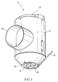
- Fig. 1 is an isometric view of the nozzle element of the invention;
- Fig. 2 is a partial cross-sectional view of the nozzle element showing the vacuum chamber and air jet member;
- Fig. 3 is a bottom view of the nozzle element of Fig. 2; and,
- Fig. 4 is a front elevational view of the laser head showing an attenuating screen therein.
-
- Turning now to the drawings, and particularly to Figs. 1-3, the
nozzle element 10 according to the principles of the invention is illustrated. According to Figs. 1 and 2,nozzle element 10 has a preferably generally cylindrical shapedchamber 12 with a laserenergy inlet end 14 and a laserenergy outlet end 16.Inlet end 14 is adaptable to any laser energy output device, such as a laser marking system for marking indicia on photosensitive web.Output end 16 is configured to focus beams of radiation onto a moving photosensitive web and to be spaced proximate to the moving photosensitive web. - Referring to Figs. 1-3, an
air jet member 18 is arranged in thechamber 12 near theoutlet end 16. Air toair jet member 18 may be supplied by any general source (not shown).Air jet member 18 is configured for directing a burst of air onto a laser beam impingeable surface, such as a photosensitive web positioned proximate to theair jet member 18. - Referring to Fig. 2,
chamber 12 has at least onelens 20 arranged therein for focusing each one of a plurality of laser beams passing through thechamber 12.Lens 20 is preferably a short focal length zinc selenide lens.Lens 20 may be mounted in any one of a variety of ways inchamber 12, for instance using a typical lens mount (not shown). - Referring to Fig. 4, a
lens cleaning member 22 is arranged in thechamber 12 proximate thelens 20.Nozzle element 10 was developed to keep thelens 20 clean, prevent plume and draw away vapors associated with impinging laser energy. In the preferred embodiment,lens cleaning member 22 is a positive air flow pattern surrounding thelens 20 that shields thelens 20 from particulate matter. Alternatively,lens cleaning member 22 may be a burst of air directed at the lens 20 (not shown). - Turning now to Figs. 1-3,
chamber 12 further has avacuum inlet port 24 and avacuum outlet port 26 in fluid communication with thechamber 12.Vacuum outlet port 26 provides means for evacuating thechamber 12 of smoke and debris generated during laser marking. To concentrate vacuum at a predetermined location,outlet port 26 preferably has a generally conical shape. Affluence generated by the marking process without vacuum resulted in no detection of cyanide, sulfur dioxide, hydrochloric acid, or carbon monoxide. Carbon dioxide could be detected but the level was below exposure limits. Mercury, silver and aldehydes vapors were adequately removed by the Fumex FA2 fume extraction machine. -
Vacuum inlet port 24, connected to a source of vacuum (not shown), provides a means for receiving such particulates that are ejected throughvacuum outlet port 26. - Referring to Fig. 4, illustrated is the
nozzle element 10 adapted to alaser beam tube 30 having a plurality oflasers 32 therein.Laser beam tube 30 is preferably the output end of a laser marking system 34 (only partially shown). - Preferably,
nozzle element 10 is made from any structurally rigid material such as any metallic material. We prefer using aluminum because it is light-weight and can be easily formed. - In operation,
nozzle element 10 is adapted to alaser beam tube 30 of alaser marking system 34. Laser beams generated by a plurality oflasers 32 pass through thenozzle element 10 and are focused bylens 20 in a predetermined pattern onto a photosensitive web (not shown). Debris, such as plume of smoke, generated by the laser energy striking the photosensitive web is drawn away from the web and into and through thechamber 12 via the vacuum inlet andoutlet ports air surrounding lens 20 defininglens cleaning member 22 keepslens 20 from accumulating particulates during laser marking. In this way, the focus of the laser beams is not distorted during operations.
Claims (5)
- A nozzle element for a laser beam tube, comprising:a chamber having a laser energy inlet end and a laser energy outlet end;an air jet member arranged in said chamber for directing a burst of air onto a laser beam impingeable surface;at least one lens arranged in said chamber for focusing each one of a plurality of laser beams passing through said chamber;a lens cleaning member arranged in said chamber proximate to said at least one lens; anda vacuum port extending from said chamber, said vacuum port providing means for evacuating said chamber of smoke and debris generated during laser marking.
- The nozzle element recited in claim 1 wherein said at least one lens is adjustably mounted in said chamber for adjusting the focus of said each one of a plurality of laser beams.
- The nozzle element recited in claim 1 wherein said laser energy outlet end of said chamber is configured for arrangement proximate to a moving photosensitive web.
- The nozzle element recited in claim 1 wherein said lens cleaning member comprises a positive air flow pattern shielding said at least one lens from particulate matter.
- The nozzle element recited in claim 1 wherein said laser energy outlet end is substantially conical shaped for concentrating vacuum on a predetermined location.
Applications Claiming Priority (2)
| Application Number | Priority Date | Filing Date | Title |
|---|---|---|---|
| US490914 | 2000-01-25 | ||
| US09/490,914 US6326590B1 (en) | 2000-01-25 | 2000-01-25 | Nozzle element adaptable to a laser beam tube used in laser edge marking equipment |
Publications (1)
| Publication Number | Publication Date |
|---|---|
| EP1120684A1 true EP1120684A1 (en) | 2001-08-01 |
Family
ID=23950032
Family Applications (1)
| Application Number | Title | Priority Date | Filing Date |
|---|---|---|---|
| EP01200116A Withdrawn EP1120684A1 (en) | 2000-01-25 | 2001-01-15 | Laser marking system |
Country Status (3)
| Country | Link |
|---|---|
| US (1) | US6326590B1 (en) |
| EP (1) | EP1120684A1 (en) |
| JP (1) | JP2001272792A (en) |
Cited By (3)
| Publication number | Priority date | Publication date | Assignee | Title |
|---|---|---|---|---|
| WO2003072439A1 (en) * | 2002-02-21 | 2003-09-04 | Stora Enso Baienfurt Gmbh & Co. Kg | Method and device for producing packagings |
| WO2007082583A3 (en) * | 2006-01-18 | 2007-12-06 | Murrplastik Systemtechnik Gmbh | Device for inscribing identification plates |
| EP2131992A4 (en) * | 2007-01-16 | 2017-03-01 | Tetra Laval Holdings & Finance S.A. | An apparatus for laser-processing of a packaging material web |
Families Citing this family (6)
| Publication number | Priority date | Publication date | Assignee | Title |
|---|---|---|---|---|
| US6556273B1 (en) | 1999-11-12 | 2003-04-29 | Eastman Kodak Company | System for providing pre-processing machine readable encoded information markings in a motion picture film |
| AU2003235957A1 (en) * | 2002-05-13 | 2003-11-11 | Disco Corporation | Finishing machine using laser beam |
| JP4136460B2 (en) * | 2002-05-29 | 2008-08-20 | 富士フイルム株式会社 | Web processing method and processing apparatus |
| US7908968B2 (en) * | 2007-06-13 | 2011-03-22 | Mccoin Jerry Wayne | Vertical marking system |
| US7947919B2 (en) | 2008-03-04 | 2011-05-24 | Universal Laser Systems, Inc. | Laser-based material processing exhaust systems and methods for using such systems |
| US8641488B1 (en) * | 2009-06-18 | 2014-02-04 | Buffalo Filter Llc | Intake apparatus and system |
Citations (6)
| Publication number | Priority date | Publication date | Assignee | Title |
|---|---|---|---|---|
| US3626141A (en) * | 1970-04-30 | 1971-12-07 | Quantronix Corp | Laser scribing apparatus |
| US4554560A (en) * | 1982-11-25 | 1985-11-19 | Fuji Photo Film Co., Ltd. | Side printing apparatus |
| US4942284A (en) * | 1988-02-24 | 1990-07-17 | Lectra Systemes | Laser cutting apparatus provided with a gas evacuation device |
| EP0519391A1 (en) * | 1991-06-18 | 1992-12-23 | Eastman Kodak Company | Laser edgemarking equipment |
| WO1998011495A1 (en) * | 1996-09-11 | 1998-03-19 | Domino Printing Sciences Plc | Laser apparatus |
| DE19800783A1 (en) * | 1998-01-12 | 1999-07-22 | Laser Show Technik Lke | Nozzle plate arrangement for projection wall for laser light allowing high-resolution projection |
Family Cites Families (9)
| Publication number | Priority date | Publication date | Assignee | Title |
|---|---|---|---|---|
| US3866398A (en) * | 1973-12-20 | 1975-02-18 | Texas Instruments Inc | In-situ gas-phase reaction for removal of laser-scribe debris |
| US4027137A (en) * | 1975-09-17 | 1977-05-31 | International Business Machines Corporation | Laser drilling nozzle |
| US4162390A (en) * | 1977-10-03 | 1979-07-24 | The International Nickel Company, Inc. | Laser welding chamber |
| US4315133A (en) * | 1980-05-12 | 1982-02-09 | Gte Automatic Electric Laboratories, Inc. | Apparatus protecting a lens from airborne particulates |
| US4303824A (en) * | 1980-05-12 | 1981-12-01 | Gte Automatic Electric Laboratories, Inc. | Method and apparatus protecting a lens from airborne particulates |
| US4652722A (en) | 1984-04-05 | 1987-03-24 | Videojet Systems International, Inc. | Laser marking apparatus |
| US5609780A (en) | 1994-11-14 | 1997-03-11 | International Business Machines, Corporation | Laser system |
| JP3191201B2 (en) * | 1996-06-26 | 2001-07-23 | コニカ株式会社 | Marking method for photosensitive material |
| US6191382B1 (en) | 1998-04-02 | 2001-02-20 | Avery Dennison Corporation | Dynamic laser cutting apparatus |
-
2000
- 2000-01-25 US US09/490,914 patent/US6326590B1/en not_active Expired - Lifetime
-
2001
- 2001-01-15 EP EP01200116A patent/EP1120684A1/en not_active Withdrawn
- 2001-01-22 JP JP2001013144A patent/JP2001272792A/en active Pending
Patent Citations (6)
| Publication number | Priority date | Publication date | Assignee | Title |
|---|---|---|---|---|
| US3626141A (en) * | 1970-04-30 | 1971-12-07 | Quantronix Corp | Laser scribing apparatus |
| US4554560A (en) * | 1982-11-25 | 1985-11-19 | Fuji Photo Film Co., Ltd. | Side printing apparatus |
| US4942284A (en) * | 1988-02-24 | 1990-07-17 | Lectra Systemes | Laser cutting apparatus provided with a gas evacuation device |
| EP0519391A1 (en) * | 1991-06-18 | 1992-12-23 | Eastman Kodak Company | Laser edgemarking equipment |
| WO1998011495A1 (en) * | 1996-09-11 | 1998-03-19 | Domino Printing Sciences Plc | Laser apparatus |
| DE19800783A1 (en) * | 1998-01-12 | 1999-07-22 | Laser Show Technik Lke | Nozzle plate arrangement for projection wall for laser light allowing high-resolution projection |
Cited By (3)
| Publication number | Priority date | Publication date | Assignee | Title |
|---|---|---|---|---|
| WO2003072439A1 (en) * | 2002-02-21 | 2003-09-04 | Stora Enso Baienfurt Gmbh & Co. Kg | Method and device for producing packagings |
| WO2007082583A3 (en) * | 2006-01-18 | 2007-12-06 | Murrplastik Systemtechnik Gmbh | Device for inscribing identification plates |
| EP2131992A4 (en) * | 2007-01-16 | 2017-03-01 | Tetra Laval Holdings & Finance S.A. | An apparatus for laser-processing of a packaging material web |
Also Published As
| Publication number | Publication date |
|---|---|
| JP2001272792A (en) | 2001-10-05 |
| US6326590B1 (en) | 2001-12-04 |
Similar Documents
| Publication | Publication Date | Title |
|---|---|---|
| US6400389B1 (en) | Apparatus for laser marking indicia on a photosensitive web | |
| US6326590B1 (en) | Nozzle element adaptable to a laser beam tube used in laser edge marking equipment | |
| CA1194297A (en) | Curing apparatus and method | |
| US5614339A (en) | Object recycling by laser of coating material | |
| JPS62127190A (en) | Method of cutting sheet material by laser | |
| DE60141787D1 (en) | DEVICE FOR INK RADIATION RECORDING | |
| US6494965B1 (en) | Method and apparatus for removal of laser ablation byproducts | |
| JPS6251101B2 (en) | ||
| EP1627746A2 (en) | Printing device with radiation source | |
| EP1120186B1 (en) | Apparatus for laser marking indicia on a photosensitive web | |
| CA1327156C (en) | Apparatus and process for processing printing plates | |
| US6249308B1 (en) | Method of controlling peak power of a radiant energy emitting system | |
| JP2000141596A (en) | Mist confining device for spray type moistening apparatus | |
| JPH07100670A (en) | Laser processing equipment | |
| CN107407902A (en) | Remove the printing unit | |
| JPH07112296A (en) | Laser processing equipment | |
| JP2018513993A (en) | Unprint cartridge | |
| JP4382390B2 (en) | Plate making equipment | |
| US20030146953A1 (en) | Conditioning ink jet orifices | |
| JP2004066517A (en) | Method for marking photosensitive material | |
| US20040003736A1 (en) | System and method of cleaning impression cylinders of a sheet-fed lithographic printing press | |
| JP2004090071A (en) | Laser marking process | |
| JPS6035736B2 (en) | Laser recording device | |
| EP1084831A2 (en) | Apparatus for collecting residual materials dispersed during imaging of flexographic printing plates | |
| JP2004188843A (en) | Method and apparatus for marking |
Legal Events
| Date | Code | Title | Description |
|---|---|---|---|
| PUAI | Public reference made under article 153(3) epc to a published international application that has entered the european phase |
Free format text: ORIGINAL CODE: 0009012 |
|
| AK | Designated contracting states |
Kind code of ref document: A1 Designated state(s): DE FR GB IT NL |
|
| AX | Request for extension of the european patent |
Free format text: AL;LT;LV;MK;RO;SI |
|
| 17P | Request for examination filed |
Effective date: 20020110 |
|
| AKX | Designation fees paid |
Free format text: DE FR GB IT NL |
|
| 17Q | First examination report despatched |
Effective date: 20040318 |
|
| STAA | Information on the status of an ep patent application or granted ep patent |
Free format text: STATUS: THE APPLICATION IS DEEMED TO BE WITHDRAWN |
|
| 18D | Application deemed to be withdrawn |
Effective date: 20040729 |