EP1120567A2 - Variable swash plate compressor - Google Patents
Variable swash plate compressor Download PDFInfo
- Publication number
- EP1120567A2 EP1120567A2 EP01300382A EP01300382A EP1120567A2 EP 1120567 A2 EP1120567 A2 EP 1120567A2 EP 01300382 A EP01300382 A EP 01300382A EP 01300382 A EP01300382 A EP 01300382A EP 1120567 A2 EP1120567 A2 EP 1120567A2
- Authority
- EP
- European Patent Office
- Prior art keywords
- swash plate
- compressor
- piston
- drive shaft
- fluid
- Prior art date
- Legal status (The legal status is an assumption and is not a legal conclusion. Google has not performed a legal analysis and makes no representation as to the accuracy of the status listed.)
- Withdrawn
Links
Images

Classifications
-
- F—MECHANICAL ENGINEERING; LIGHTING; HEATING; WEAPONS; BLASTING
- F04—POSITIVE - DISPLACEMENT MACHINES FOR LIQUIDS; PUMPS FOR LIQUIDS OR ELASTIC FLUIDS
- F04B—POSITIVE-DISPLACEMENT MACHINES FOR LIQUIDS; PUMPS
- F04B19/00—Machines or pumps having pertinent characteristics not provided for in, or of interest apart from, groups F04B1/00 - F04B17/00
-
- F—MECHANICAL ENGINEERING; LIGHTING; HEATING; WEAPONS; BLASTING
- F04—POSITIVE - DISPLACEMENT MACHINES FOR LIQUIDS; PUMPS FOR LIQUIDS OR ELASTIC FLUIDS
- F04B—POSITIVE-DISPLACEMENT MACHINES FOR LIQUIDS; PUMPS
- F04B1/00—Multi-cylinder machines or pumps characterised by number or arrangement of cylinders
- F04B1/12—Multi-cylinder machines or pumps characterised by number or arrangement of cylinders having cylinder axes coaxial with, or parallel or inclined to, main shaft axis
- F04B1/26—Control
- F04B1/28—Control of machines or pumps with stationary cylinders
- F04B1/29—Control of machines or pumps with stationary cylinders by varying the relative positions of a swash plate and a cylinder block
- F04B1/295—Control of machines or pumps with stationary cylinders by varying the relative positions of a swash plate and a cylinder block by changing the inclination of the swash plate
Definitions
- the present invention relates generally to a swash plate compressor and more particularly to improvements to such a compressor so that the size, energy consumption, and vibrational characteristics are minimized.
- Conventional swash plate compressors utilize a rotating swash plate, driven by a drive shaft, to drive a piston.
- the piston is used to transfer fluid from the low pressure side of an air conditioning system or other device to the high pressure side.
- Conventional swash plate compressors utilize an elbow to transfer the rotational drive of the drive shaft to the swash plate.
- the utilization of an elbow, or similar mechanism, to transfer the rotational drive of the drive shaft has several undesirable characteristics. This conventional design transfers undesirable stresses to the swash plate requiring the swash plate to be designed for a higher strength. This adds to the size, weight, and cost of the swash plate compressor.
- the presence alone of the elbow or similar mechanism adds to the size, weight, complexity and manufacturing cost of the conventional swash plate compressor.
- the elbow as it rotates with the drive shaft, limits the potential travel distance of the piston.
- variable swash plate compressors utilize multiple pivot locations.
- the swash plate itself typically slides and/or rotates axially on the drive shaft, the elbow joint slides and/or rotates about a pin in the elbow, and the piston joint rotates about its connection with the swash plate.
- the position and rotation of the swash plate, the elbow, and the piston in relation to each pivot location controls the path of the piston.
- These multiple pivot locations often result in a variable Top-Dead-Center (“TDC") of the piston.
- TDC of the piston is the distance between the piston face and the piston chamber outlet face at the top of the piston cycle. Variations in the piston TDC result in undesirable variations in the variable swash plate compressor's output.
- variable swash plate compressor design that reduces the stresses in the swash plate, allows for greater piston travel without increasing the compressor size, reduces undesirable vibrational characteristics, reduces variation in piston TDC, and reduces the size, weight, and manufacturing cost of known variable swash plate compressor designs.
- variable swash plate compressor that reduces the stress in the swash plate, reduces vibrations in the compressor, and reduces the variation in piston TDC. It is a further object of the present invention to provide a variable swash plate compressor that reduces the size, weight, and manufacturing costs associated with conventional swash plate compressor design.
- variable swash plate compressor in accordance with the objects of this invention, includes a housing, a drive shaft and a control surface element.
- the control surface element is attached to and receives a rotational drive force from the drive shaft.
- the control surface element has a pinnacle element attached thereto.
- the variable swash plate compressor also includes a swash plate with a bore located in its center.
- the control surface element sits within the bore of the swash plate.
- the swash plate also includes a pocket in which the pinnacle element is seated.
- the drive shaft transmits a rotational drive force to the swash plate through the control surface element seated in the bore of the swash plate and the pinnacle element seated in the swash plate pocket.
- the variable swash plate compressor also includes a compression piston positioned within a piston chamber formed in the housing. As the compression piston moves within the piston chamber it alternates between drawing fluid into the piston chamber through an inlet and forcing fluid within the piston chamber out of an outlet. The compression piston is moved in this cyclical fashion by remaining in contact with the rotating swash plate such that only axial forces are transmitted between the swash plate and the compression piston. As the angle between the swash plate and the drive shaft is increased, the travel path of the compression piston is increased resulting in an increase in the output of the variable swash plate compressor.
- the variable swash plate compressor also includes a fulcrum piston assembly for controlling the angle of the swash plate relative to the drive shaft. As the angle of the swash plate relative to the drive shaft is increased, the output of the variable swash plate compressor is increased.
- the fulcrum piston assembly changes the angle of the swash plate by exerting a force on the swash plate causing it to pivot about the tip of the pinnacle element. The tip of the pinnacle element orbits the axial center of the drive shaft at a distance equal to the distance from the center of the drive shaft to the axial center of the compression piston.
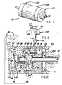
- FIG. 1 is a schematic view of a variable swash plate compressor 10 in accordance with the present invention.
- the disclosed variable swash plate compressor 10 is preferably for use in automotive air conditioning applications.
- the disclosed variable swash plate compressor 10 may be used in a variety of applications, including non-automotive applications.
- the variable swash plate compressor 10 includes a housing 12.
- the housing 12 is comprised of a top housing section 12A, a middle housing section 12B, and a bottom housing section 12C.
- a top inlet 14A is located within the top housing 12A and is in fluid connection with a bottom inlet 14B located within the bottom housing 12C to allows fluid to be conveyed into a pumping chamber 16 located within the middle housing 12B.
- the bottom inlet 14B is in fluid communication with a source of fluid outside the compressor 10.
- a compression piston 18 situated within the pumping chamber 16 draws fluid from the top inlet 14A into the pumping chamber 16 and is used to force the fluid within the pumping chamber 16 out through a top outlet 20A.
- the top outlet 20A is in fluid connection with a bottom outlet 20B to allow fluid from the top outlet 20A and the bottom outlet 20B to exit the bottom housing section 12C of the compressor 10.
- the compression piston 18 is activated through the use of a drive shaft 22 located with the housing 12.
- the drive shaft 22 is imparted with a rotational drive force from a source outside the variable swash plate compressor 10.
- the drive shaft 22 may be imparted with a rotational drive force from a source within the variable swash plate compressor 10.
- a control surface element 24 is affixed to the drive shaft 22 and rotates in unison with the drive shaft 22.
- a pivot element 26 is affixed to the control surface element 24 and travels in a path radially around the axis of the drive shaft 22.
- Figures 3A and 3B illustrate the assembly of the drive shaft 22, the control surface 24 and the pivot element 26.
- the drive shaft 22, the control surface element 24, and the pivot element 26 may all be formed as a single element.
- the drive shaft 22 As the drive shaft 22 rotates, it imparts a drive force through the control surface 24 and the pivot element 26 to a swash plate 28.
- the swash plate 28 is formed with a bore 30 in which the control surface element 24 sits.
- the swash plate 28 is additionally formed with a pocket 32 in which the pivot element 26 sits.
- Figures 4A and 4B illustrate the swash plate 28, the bore 30 and the pocket 32.
- the pocket 32 is preferably formed in the center plane of the swash plate 28 such that the drive imparted to the swash plate 28 is primarily rotational and such that stresses within the swash plate 28 are minimized.
- the swash plate 28 is connected to the compression piston 18 through the use of a ball joint 36 located within a generally c-shaped opening 38 in the compression piston 18.
- the ball joint 36 prevents the majority of the rotational drive force of the swash plate 28 from being transmitted to the compression piston 18.
- the angle ⁇ of the swash plate 28 is increased by pivoting the swash plate 28 about the pivot element 26 (see Figure 6).
- the pocket 32 located within the swash plate 28 and the pivot element 26 are shaped such that the swash plate 28 pivots about the pivot element tip 39.
- the pivot element tip 39 is positioned at a distance from the axial center of the drive shaft 22 approximately equal to the distance from the axial center of the compression piston 18 to the axial center of the drive shaft 22.
- TDC top-dead-center
- Minimization of TDC variations allows for greater control of the variable swash plate compressor 10 output.
- the angle ⁇ of the swash plate 28 is varied through the use of a fulcrum piston assembly 40.
- the fulcrum piston assembly is comprised of a fulcrum element 41 and a control piston 42.
- the fulcrum element 41 is connected to the control piston 42 through the use of thrust bearings 44 to allow the fulcrum element 41 to rotate with the drive shaft 22.
- Fluid pressure in the output chamber 46 controls the position of the fulcrum piston assembly 40 and subsequently the angle ⁇ .
- the output chamber 46 remains in fluid communication with the bottom outlet 20B.
- a control valve 48 through a connection 49 with the output chamber 46, increases the pressure in the output chamber 46 during periods where increased compressor capacity is required.
- the control valve 48 allows the fluid pressure in the output chamber 46 to drop and the fulcrum piston assembly 40 drops allowing the swash plate 28 to position itself nearly perpendicular to the drive shaft 22.
- the control valve 48 may also be used to allow a bleed line, with a bleed input 50 and a bleed output 52, to allow portions of fluid from either the top inlet 14A or the bottom inlet 14B to be in fluid communication with the crankcase 54. This allows moving parts within the crankcase 54 to be cooled and lubricated.
- variable swash plate compressor 10 Although the present embodiment was described with a single compression piston 18, multiple compression pistons may be used in the variable swash plate compressor 10. One embodiment makes use of five compression pistons.
Landscapes
- Engineering & Computer Science (AREA)
- Mechanical Engineering (AREA)
- General Engineering & Computer Science (AREA)
- Compressors, Vaccum Pumps And Other Relevant Systems (AREA)
Abstract
Description
Claims (10)
- A compressor comprising:a housing;a drive shaft;a control surface element attached to said drive shaft, wherein said drive shaft transmits a rotational drive force to said control surface element;a pinnacle element attached to said control surface element;a swash plate, wherein as the angle of said swash plate relative to a position perpendicular to said drive shaft increases, the output of the compressor is increased;a bore formed in said swash plate, wherein said control surface element sits within said bore;a pocket formed in said swash plate, wherein said pinnacle element sits within said pocket;a fulcrum piston assembly to control the angle of said swash plate, wherein said swash plate pivots about the tip of said pinnacle element;at least one compression piston in contact with said swash plate wherein said swash plate transmits primarily axial loads to said at least one compression piston;at least one piston chamber formed within said housing and containing said at least one compression piston;at least one top inlet providing fluid to said at least one piston chamber;at least one bottom inlet in fluid communication with said at least one top inlet and in communication with a fluid source outside of the compressor;at least one top outlet permitting fluid to exit the top of said at least one piston chamber;at least one bottom outlet in fluid communication with said at least one top outlet;wherein said pinnacle element has a tip that orbits the axial center of said drive shaft at a distance equal to the distance from the axial center of said drive shaft to the axial center of said at least one compression piston;
- A compressor as described in claim 1, wherein said control surface element transmits said rotational drive force to said swash plate such that said swash plate rotates with said drive shaft.
- A compressor as described in claim 1, wherein said pinnacle element transmits said rotational drive force to said swash plate such that said swash plate rotates with said drive shaft.
- A compressor as described in claim 1, further comprising:a fluid pressure chamber in fluid communication with said at least one bottom outlet, wherein the pressure of fluid in said fluid pressure chamber is varied to adjust the compressor output; anda control valve used to control pressure in said pressure chamber, wherein the pressure of fluid within said fluid pressure chamber is increased to increase the compressor output;wherein the pressure of the fluid in said fluid pressure chamber is used to control said fulcrum piston assembly.
- A compressor as described in claim 4, wherein said fulcrum piston assembly comprises:a control piston in connection with fluid in said fluid pressure chamber;a fulcrum element rotatably attached to said control piston, wherein said fulcrum element rotates with said drive shaft;wherein as pressure is increased in said fluid pressure chamber, said fulcrum piston assembly is moved towards said swash plate thereby increasing the angle of said swash plate relative to the drive shaft.
- A compressor as described in claim 4, wherein said control valve further comprises:
a bleed line wherein a portion of fluid from said at least one bottom inlet is in fluid connection with a crankcase. - A compressor as described in claim 1, wherein said pocket is formed along the center plane of said swash plate.
- A compressor as described in claim 1, wherein said drive shaft, said control surface element and said pinnacle element are formed as a single element.
- A compressor as described in claim 1, wherein said control surface element and said pinnacle element are formed as a single element.
- A compressor as described in claim 1, further comprising:a generally c-shaped opening located within said at least one compressor piston; anda ball joint positioned within said generally c-shaped opening wherein said ball joint remains in slidable contact with said swash plate;wherein the primary forces transferred from said swash plate to said at least one compression piston are primarily limited to forces in the axial direction of said at least one compression piston.
Applications Claiming Priority (2)
| Application Number | Priority Date | Filing Date | Title |
|---|---|---|---|
| US09/492,431 US6210124B1 (en) | 2000-01-27 | 2000-01-27 | Variable swash plate compressor |
| US492431 | 2000-01-27 |
Publications (2)
| Publication Number | Publication Date |
|---|---|
| EP1120567A2 true EP1120567A2 (en) | 2001-08-01 |
| EP1120567A3 EP1120567A3 (en) | 2003-01-29 |
Family
ID=23956222
Family Applications (1)
| Application Number | Title | Priority Date | Filing Date |
|---|---|---|---|
| EP01300382A Withdrawn EP1120567A3 (en) | 2000-01-27 | 2001-01-17 | Variable swash plate compressor |
Country Status (3)
| Country | Link |
|---|---|
| US (1) | US6210124B1 (en) |
| EP (1) | EP1120567A3 (en) |
| KR (1) | KR20010078062A (en) |
Families Citing this family (2)
| Publication number | Priority date | Publication date | Assignee | Title |
|---|---|---|---|---|
| AU2002213826A1 (en) * | 2000-11-10 | 2002-05-21 | Luk Fahrzeug-Hydraulik Gmbh And Co. Kg | Reciprocating piston engine |
| US20100074765A1 (en) * | 2003-04-04 | 2010-03-25 | Otfried Schwarzkopf | Reciprocating Compressor, in Particular CO2 Compressor for Vehicle Air-Conditioning Units |
Family Cites Families (12)
| Publication number | Priority date | Publication date | Assignee | Title |
|---|---|---|---|---|
| US4425837A (en) | 1981-09-28 | 1984-01-17 | General Motors Corporation | Variable displacement axial piston machine |
| JPH0733822B2 (en) * | 1986-09-03 | 1995-04-12 | 株式会社日立製作所 | Variable capacity compressor |
| JPS6477771A (en) | 1987-09-18 | 1989-03-23 | Hitachi Ltd | Variable delivery compressor |
| DE3743125A1 (en) | 1987-12-18 | 1989-07-06 | Brueninghaus Hydraulik Gmbh | AXIAL PISTON PUMP |
| US4963074A (en) | 1988-01-08 | 1990-10-16 | Nippondenso Co., Ltd. | Variable displacement swash-plate type compressor |
| JPH0264275A (en) | 1988-05-25 | 1990-03-05 | Nippon Soken Inc | Variable-displacement swash plate type compressor |
| DE3924347A1 (en) * | 1988-07-22 | 1990-02-01 | Toyoda Automatic Loom Works | Swashplate compressor with variable flow - has angle of swashplate changed by pressure acting on central piston |
| JP2626292B2 (en) | 1991-03-30 | 1997-07-02 | 株式会社豊田自動織機製作所 | Variable capacity swash plate compressor |
| JP3066879B2 (en) * | 1991-07-16 | 2000-07-17 | 株式会社デンソー | Variable displacement swash plate type compressor |
| JPH05172052A (en) | 1991-12-18 | 1993-07-09 | Sanden Corp | Variable displacement swash plate type compressor |
| JPH05312144A (en) * | 1992-05-08 | 1993-11-22 | Sanden Corp | Variable displacement swash plate type compressor |
| GB2280936B (en) | 1993-08-11 | 1997-03-26 | Kubota Kk | Structure for adjusting swash plate angle of a variable displacement hydraulic motor |
-
2000
- 2000-01-27 US US09/492,431 patent/US6210124B1/en not_active Expired - Fee Related
-
2001
- 2001-01-17 EP EP01300382A patent/EP1120567A3/en not_active Withdrawn
- 2001-01-26 KR KR1020010003687A patent/KR20010078062A/en not_active Withdrawn
Also Published As
| Publication number | Publication date |
|---|---|
| KR20010078062A (en) | 2001-08-20 |
| EP1120567A3 (en) | 2003-01-29 |
| US6210124B1 (en) | 2001-04-03 |
Similar Documents
| Publication | Publication Date | Title |
|---|---|---|
| JP2555026B2 (en) | Variable capacity compressor | |
| US5173032A (en) | Non-clutch compressor | |
| US5259736A (en) | Swash plate type compressor with swash plate hinge coupling mechanism | |
| CN1138921C (en) | Capacity variable compressor and control valve used for same | |
| EP0635640B1 (en) | Bearing structure used in a compressor | |
| EP1001169A2 (en) | Variable capacity swash plate type compressor | |
| JPH05312144A (en) | Variable displacement swash plate type compressor | |
| EP1039129A2 (en) | Device and method for controlling displacement of variable displacement compressor | |
| US6742439B2 (en) | Variable displacement compressor | |
| US5931079A (en) | Variable capacity swash plate compressor | |
| JPH0337378A (en) | Clutchless compressor | |
| US20050058551A1 (en) | Swash plate type variable displacement compressor | |
| KR970003245B1 (en) | Compressor with variable displacement mechanism | |
| US6210124B1 (en) | Variable swash plate compressor | |
| US5713725A (en) | Clutchless piston type variable displacement compressor | |
| US6354809B1 (en) | Variable swash plate compressor | |
| US6276904B1 (en) | Variable capacity refrigerant compressor having an inclination limiting means to interrupt compressive forces on a hinge mechanism | |
| EP2096307A2 (en) | Tilting plate type compressor | |
| US20010029837A1 (en) | Hinge mechanism for variable displacement compressor | |
| US7320576B2 (en) | Clutchless variable displacement refrigerant compressor with mechanism for reducing displacement work at increased driven speed during non-operation of refrigerating system including the compressor | |
| JP2006291748A (en) | Piston type variable displacement compressor | |
| EP1043500A2 (en) | Pivot joint for a swash plate of a variable displacement compressor | |
| JP2013245632A (en) | Variable-displacement compressor | |
| KR102760181B1 (en) | Variable displacement swash plate type compressor | |
| US20020184999A1 (en) | Fixed displacement compressors |
Legal Events
| Date | Code | Title | Description |
|---|---|---|---|
| PUAI | Public reference made under article 153(3) epc to a published international application that has entered the european phase |
Free format text: ORIGINAL CODE: 0009012 |
|
| AK | Designated contracting states |
Kind code of ref document: A2 Designated state(s): AT BE CH CY DE DK ES FI FR GB GR IE IT LI LU MC NL PT SE TR |
|
| AX | Request for extension of the european patent |
Free format text: AL;LT;LV;MK;RO;SI |
|
| PUAL | Search report despatched |
Free format text: ORIGINAL CODE: 0009013 |
|
| AK | Designated contracting states |
Designated state(s): AT BE CH CY DE DK ES FI FR GB GR IE IT LI LU MC NL PT SE TR |
|
| AX | Request for extension of the european patent |
Extension state: AL LT LV MK RO SI |
|
| 17P | Request for examination filed |
Effective date: 20030220 |
|
| AKX | Designation fees paid |
Designated state(s): DE ES |
|
| RBV | Designated contracting states (corrected) |
Designated state(s): DE GB |
|
| STAA | Information on the status of an ep patent application or granted ep patent |
Free format text: STATUS: THE APPLICATION HAS BEEN WITHDRAWN |
|
| 18W | Application withdrawn |
Effective date: 20031202 |