EP1120304A1 - Open roof construction for a vehicle, as well as a sunscreen for use therein - Google Patents
Open roof construction for a vehicle, as well as a sunscreen for use therein Download PDFInfo
- Publication number
- EP1120304A1 EP1120304A1 EP01200260A EP01200260A EP1120304A1 EP 1120304 A1 EP1120304 A1 EP 1120304A1 EP 01200260 A EP01200260 A EP 01200260A EP 01200260 A EP01200260 A EP 01200260A EP 1120304 A1 EP1120304 A1 EP 1120304A1
- Authority
- EP
- European Patent Office
- Prior art keywords
- screen
- opening
- roof
- roof construction
- open
- Prior art date
- Legal status (The legal status is an assumption and is not a legal conclusion. Google has not performed a legal analysis and makes no representation as to the accuracy of the status listed.)
- Granted
Links
- 230000000475 sunscreen effect Effects 0.000 title claims abstract description 46
- 239000000516 sunscreening agent Substances 0.000 title claims abstract description 46
- 238000010276 construction Methods 0.000 title claims abstract description 29
- 239000000203 mixture Substances 0.000 claims 1
- 239000000463 material Substances 0.000 description 6
- 238000001746 injection moulding Methods 0.000 description 3
- 230000007246 mechanism Effects 0.000 description 3
- 239000004744 fabric Substances 0.000 description 1
- 239000004519 grease Substances 0.000 description 1
- 238000002156 mixing Methods 0.000 description 1
- 239000004753 textile Substances 0.000 description 1
- 238000009423 ventilation Methods 0.000 description 1
Images



Classifications
-
- B—PERFORMING OPERATIONS; TRANSPORTING
- B60—VEHICLES IN GENERAL
- B60J—WINDOWS, WINDSCREENS, NON-FIXED ROOFS, DOORS, OR SIMILAR DEVICES FOR VEHICLES; REMOVABLE EXTERNAL PROTECTIVE COVERINGS SPECIALLY ADAPTED FOR VEHICLES
- B60J7/00—Non-fixed roofs; Roofs with movable panels, e.g. rotary sunroofs
- B60J7/0007—Non-fixed roofs; Roofs with movable panels, e.g. rotary sunroofs moveable head-liners, screens, curtains or blinds for ceilings
- B60J7/003—Non-fixed roofs; Roofs with movable panels, e.g. rotary sunroofs moveable head-liners, screens, curtains or blinds for ceilings one or more sliding rigid plate or lammellae
Definitions
- the present invention relates to an open roof construction for a vehicle having an opening in its fixed roof, comprising a stationary part to be fixed to the roof, an adjustable upper closure element supported by said stationary part, which is adjustable between a closed position, in which it closes the roof opening, and an open position, in which it opens the roof opening at least partially, as well as a lower closure element, in particular a sun screen in the form of a slidable, substantially rigid screen, which is provided with at least one ventilating opening for passing air through the screen.
- Open roof constructions of this kind are known in several versions thereof. Examples are to be found in DE-A-29 23 888, US-A-4,717,200, DE-C-195 11 067, DE-C-195 19 811 and DE-A-198 21 358.
- the object of the invention is to provide a new open roof construction of the kind referred to in the introduction.
- the open roof construction according to the invention is characterized in that said screen comprises horizontally overlapping parts, at least adjacent to said ventilating opening, which prevent direct incidence of light through the screen.
- the invention provides a screen which does pass air, and consequently provides ventilation, but which allows hardly any incidence of light, if at all, at least no direct incidence of light.
- the overlapping parts of the screen are formed in such a manner that a shaded edge is formed on the underside of the screen in use, at the location of said overlapping parts, rather than patches of light, as is the case with the prior art where the overlapping parts are discontinuous or interrupted.
- the overlapping parts can be formed by making the screen double-walled, with an upper part and a lower part, and by giving said parts different dimensions and having them overlap at least partially.
- the overlapping parts can form a ventilating gap which is covered from the upper side, which ventilating gap extends in the longitudinal direction of the screen or transversely thereto. According to another possibility, the ventilating gap extends along the entire circumference of the screen.
- the ventilating openings may adjoin said gap between the upper part and the lower part in that case, they may for example be disposed near the front edge and the rear edge of the screen.
- the ventilating openings may be formed of separate parts formed of plastic material, for example by means of an injection moulding process, which parts may have been attached to the screen by means of a snap connection, for example, but it is also possible to form larger parts of the screen of preformed material.
- Fig. 1 is a very schematic top plan view of a vehicle roof fitted with an exemplary embodiment of the open roof construction according to the invention.
- Fig. 2 is a perspective, longitudinal sectional view of the sun screen of the open roof construction of Fig. 1, seen from above.
- Fig. 3 shows half the screen of Fig. 2, seen in bottom plan view in this case.
- Fig. 4 is a sectional view along line IV-IV in Fig. 2.
- Fig. 5 is a bottom plan view of a variant of an embodiment of the sun screen according to the invention.
- Fig. 6 is a very schematic sectional view along line VI-VI in Fig. 5.
- Fig. 7 is a perspective, larger-scale view of a part of the underside of the screen that is shown in Figs. 5 and 6.
- Figs. 8 and 9 are a cross-sectional view and a perspective view of details of the side edge of the sun screen of Figs. 6 and 7.
- Figs. 10 and 11 are a bottom plan view and a perspective view of another exemplary embodiment of the sun screen according to the invention.
- Figs. 12 and 13 are a bottom plan view and a very schematic sectional view of another variant of an embodiment of the sun screen according to the invention, whereas Fig. 14 is a perspective view of a detail thereof.
- Figs. 15, 16 and 17 show various elevational views and sectional views, respectively, of another variant of an embodiment
- Figs. 18, 19 and 20 show a final exemplary embodiment of the sun screen according to the invention.
- Fig. 1 shows the fixed roof of a motor vehicle, in this case a passenger car.
- Said fixed roof 1 is provided with an at least substantially rectangular roof opening 2 for the purpose of mounting an open roof construction therein.
- the open roof construction comprises a stationary part, in this case a frame 3, which is fixed to the underside of the fixed roof 1 of the vehicle.
- the open roof construction is a so-called sliding roof or sliding-tilt roof, which comprises a panel 4 which is preferably transparent and which is more or less rigid in this embodiment, which panel is capable of selectively closing the roof opening 2 or releasing it to a greater or lesser extent.
- panel 4 is laterally supported by operating mechanisms 5, which are slidably accommodated in guide rails 6 which are mounted on frame 3 or which form part thereof, and which extend in longitudinal direction, parallel to each other, on either side of roof opening 2 and rearwards thereof.
- Said operating mechanisms 5 can be moved synchronously in guide rails 6 and thus move the panel not only in longitudinal direction but also in vertical direction.
- the operating mechanisms 5 are actuated from a driving device 7, such as an electric motor, for example via pull-push cables 8.
- the open roof construction also comprises a lower closure element, in this case in the form of a sun screen 9, which is slidably guided with its side edges relative to guideways 10 of guide rails 6.
- Sun screen 9 can be moved forward and rearward, for example manually or automatically, or be moved along with panel 4.
- Sun screen 9 is fitted with a number of sliding shoes 11, four sliding shoes 11 on each side edge of the sun screen in this embodiment, in order to enable sliding movement of sun screen 9 in guide grooves 10.
- Figs. 2 - 4 show the sun screen 9 in detail.
- the figures show that the sun screen is double-walled, comprising an upper part 12 and a lower part 13.
- Upper part 12 is larger than lower part 13, and thus defines the circumference of the sun screen 9.
- the circumferential edge 12' of upper part 12 is hollow, and it has a thickness such that the bottom side of circumferential edge 12' of upper part 12 is substantially flush with the bottom side of lower part 13.
- the upper side of upper part 12 is substantially flat and free from any projections.
- Lower part 13, over which cloth may be stretched, is connected to upper part 12 in a manner not shown, leaving clear a space between the two parts, which is formed as a result of the upper part curving and blending upwards above lower part 13, thus leaving clear a ventilating gap 16 therebetween.
- Ventilating openings 14 are formed in the upper part 12 of the sun screen 9, near the front edge and the rear edge of sun screen in this case, which ventilating openings open at the bottom side of upper part 12 at a location where lower part 13 overlaps upper part 12.
- said ventilating openings 14 are hidden from view to the occupants of the vehicle.
- the only thing that can be seen is the shaded edge at the circumference of part 13. In this way direct incidence of light into the interior is prevented in the closed position of the sun screen, whereas ventilating through the sun screen 9 is still possible.
- the figures furthermore show that a handgrip 15 for manual operation of sun screen 9 is formed in the bottom side of the upper part 12 of sun screen 9, at the front edge thereof. Said handgrip 15 is formed separately from the ventilating openings 14.
- Figs. 5 - 20 shows all kinds of variants of embodiments of the open roof construction according to the invention, and in particular of the sun screen thereof.
- Figs. 5 - 7 show a first variant, wherein the ventilating gap 16 does not extend along the entire circumference of sun screen 9, but only along the side edges thereof.
- sun screen 9 consists of a central part 17 and two edge parts 18, which slightly overlap said central part 17 on the upper side and wherein the overlapping parts of said central part 17 hide the ventilating openings 19 to be formed from view.
- Figs. 8 and 9 are schematic, larger-scale views of an edge part 18, which is fitted with sliding shoes 11, which sliding shoes are thus capable of guiding the movement of sun screen 9 along guideway 10.
- Figs. 10, 11 and 12 show a variant wherein the edge parts 18 are wider, and wherein the central part 17 overlaps the edge parts 18 on the upper side, so that the shaded edges are formed near the central part 17. In this way a central console as present in the roof liner of many automobiles is still formed in the sun screen 9, as it were.
- Figs. 13 and 14 show a variant of the preceding embodiment, wherein the two edge parts 18 are interconnected at the front and the rear edge of the sun screen 9, and wherein consequently the ventilating gaps 16 do not extend along the entire length of sun screen 9. In this way a central console is still formed, as it were, but the rigidity of the sun screen 9 as a whole is greater in this case.
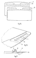
- Figs. 15, 16 and 17 show another embodiment of the sun screen according to the invention, wherein a front part 20 of sun screen 9 has been formed of plastic material as a separate part, preferably by means of an injection moulding process.
- the ventilating openings 21 and the handgrip 22 consist of plastic material, and consequently they are easier to clean.
- the other parts of the sun screen 9 may be lined with textile, for example, and be adapted to the material of the roof liner of the vehicle in question.
- Figs. 18 - 20 show a final exemplary embodiment, wherein the ventilating openings 23 are formed in separate elements, which have been made of plastic material, preferably by means of an injection moulding process.
- Said elements consist of an upper element 24 and a lower element 25.
- Lower element 25 can be inserted from below through a suitable opening 26 in sun screen 9, after which the upper element 24 can be connected to lower element 26 by snap means 27 and be attached to sun screen 9.
- Upper element 24 has a wall 28, which covers the passage 29 through lower element 25, so that there will be no direct incidence of light through sun screen 9.
- the ventilating openings 23 which allow air to pass through but which do not allow direct incidence into the interior of the vehicle, owing to the overhanging edge of the upper wall 28 of the upper element 24.
- the two elements 24 and 25, and of course opening 26 in sun screen 9, can be given any desired shape, as is illustrated in Fig. 18.
- the invention provides an open roof construction which provides adequate ventilating as well as good possibilities of being adapted to the interior of the vehicle.
Landscapes
- Engineering & Computer Science (AREA)
- Mechanical Engineering (AREA)
- Body Structure For Vehicles (AREA)
- Air-Conditioning For Vehicles (AREA)
Abstract
Description
- The present invention relates to an open roof construction for a vehicle having an opening in its fixed roof, comprising a stationary part to be fixed to the roof, an adjustable upper closure element supported by said stationary part, which is adjustable between a closed position, in which it closes the roof opening, and an open position, in which it opens the roof opening at least partially, as well as a lower closure element, in particular a sun screen in the form of a slidable, substantially rigid screen, which is provided with at least one ventilating opening for passing air through the screen.
- Open roof constructions of this kind are known in several versions thereof. Examples are to be found in DE-A-29 23 888, US-A-4,717,200, DE-C-195 11 067, DE-C-195 19 811 and DE-A-198 21 358.
- The object of the invention is to provide a new open roof construction of the kind referred to in the introduction.
- In order to accomplish that objective, the open roof construction according to the invention is characterized in that said screen comprises horizontally overlapping parts, at least adjacent to said ventilating opening, which prevent direct incidence of light through the screen.
- The invention provides a screen which does pass air, and consequently provides ventilation, but which allows hardly any incidence of light, if at all, at least no direct incidence of light. Preferably, the overlapping parts of the screen are formed in such a manner that a shaded edge is formed on the underside of the screen in use, at the location of said overlapping parts, rather than patches of light, as is the case with the prior art where the overlapping parts are discontinuous or interrupted.
- The overlapping parts can be formed by making the screen double-walled, with an upper part and a lower part, and by giving said parts different dimensions and having them overlap at least partially. The overlapping parts can form a ventilating gap which is covered from the upper side, which ventilating gap extends in the longitudinal direction of the screen or transversely thereto. According to another possibility, the ventilating gap extends along the entire circumference of the screen. The ventilating openings may adjoin said gap between the upper part and the lower part in that case, they may for example be disposed near the front edge and the rear edge of the screen. The ventilating openings may be formed of separate parts formed of plastic material, for example by means of an injection moulding process, which parts may have been attached to the screen by means of a snap connection, for example, but it is also possible to form larger parts of the screen of preformed material.
- The invention will now be explained in more detail with reference to the drawings, which show, in some case very schematically, a number of exemplary embodiments of the invention.
- Fig. 1 is a very schematic top plan view of a vehicle roof fitted with an exemplary embodiment of the open roof construction according to the invention.
- Fig. 2 is a perspective, longitudinal sectional view of the sun screen of the open roof construction of Fig. 1, seen from above.
- Fig. 3 shows half the screen of Fig. 2, seen in bottom plan view in this case.
- Fig. 4 is a sectional view along line IV-IV in Fig. 2.
- Fig. 5 is a bottom plan view of a variant of an embodiment of the sun screen according to the invention.
- Fig. 6 is a very schematic sectional view along line VI-VI in Fig. 5.
- Fig. 7 is a perspective, larger-scale view of a part of the underside of the screen that is shown in Figs. 5 and 6.
- Figs. 8 and 9 are a cross-sectional view and a perspective view of details of the side edge of the sun screen of Figs. 6 and 7.
- Figs. 10 and 11 are a bottom plan view and a perspective view of another exemplary embodiment of the sun screen according to the invention.
- Figs. 12 and 13 are a bottom plan view and a very schematic sectional view of another variant of an embodiment of the sun screen according to the invention, whereas Fig. 14 is a perspective view of a detail thereof.
- Figs. 15, 16 and 17 show various elevational views and sectional views, respectively, of another variant of an embodiment, and Figs. 18, 19 and 20 show a final exemplary embodiment of the sun screen according to the invention.
- Fig. 1 shows the fixed roof of a motor vehicle, in this case a passenger car. Said fixed
roof 1 is provided with an at least substantially rectangular roof opening 2 for the purpose of mounting an open roof construction therein. The open roof construction comprises a stationary part, in this case a frame 3, which is fixed to the underside of thefixed roof 1 of the vehicle. - In the illustrated embodiment the open roof construction is a so-called sliding roof or sliding-tilt roof, which comprises a
panel 4 which is preferably transparent and which is more or less rigid in this embodiment, which panel is capable of selectively closing theroof opening 2 or releasing it to a greater or lesser extent. To this end,panel 4 is laterally supported byoperating mechanisms 5, which are slidably accommodated inguide rails 6 which are mounted on frame 3 or which form part thereof, and which extend in longitudinal direction, parallel to each other, on either side of roof opening 2 and rearwards thereof. Saidoperating mechanisms 5 can be moved synchronously inguide rails 6 and thus move the panel not only in longitudinal direction but also in vertical direction. To this end theoperating mechanisms 5 are actuated from adriving device 7, such as an electric motor, for example via pull-push cables 8. - Besides
panel 4, the open roof construction also comprises a lower closure element, in this case in the form of asun screen 9, which is slidably guided with its side edges relative toguideways 10 ofguide rails 6.Sun screen 9 can be moved forward and rearward, for example manually or automatically, or be moved along withpanel 4.Sun screen 9 is fitted with a number of slidingshoes 11, foursliding shoes 11 on each side edge of the sun screen in this embodiment, in order to enable sliding movement ofsun screen 9 inguide grooves 10. - Figs. 2 - 4 show the
sun screen 9 in detail. The figures show that the sun screen is double-walled, comprising anupper part 12 and alower part 13.Upper part 12 is larger thanlower part 13, and thus defines the circumference of thesun screen 9. The circumferential edge 12' ofupper part 12 is hollow, and it has a thickness such that the bottom side of circumferential edge 12' ofupper part 12 is substantially flush with the bottom side oflower part 13. The upper side ofupper part 12 is substantially flat and free from any projections.Lower part 13, over which cloth may be stretched, is connected toupper part 12 in a manner not shown, leaving clear a space between the two parts, which is formed as a result of the upper part curving and blending upwards abovelower part 13, thus leaving clear aventilating gap 16 therebetween.Ventilating openings 14 are formed in theupper part 12 of thesun screen 9, near the front edge and the rear edge of sun screen in this case, which ventilating openings open at the bottom side ofupper part 12 at a location wherelower part 13 overlapsupper part 12. Thus, said ventilatingopenings 14 are hidden from view to the occupants of the vehicle. The only thing that can be seen is the shaded edge at the circumference ofpart 13. In this way direct incidence of light into the interior is prevented in the closed position of the sun screen, whereas ventilating through thesun screen 9 is still possible. - The figures furthermore show that a
handgrip 15 for manual operation ofsun screen 9 is formed in the bottom side of theupper part 12 ofsun screen 9, at the front edge thereof. Saidhandgrip 15 is formed separately from theventilating openings 14. - Figs. 5 - 20 shows all kinds of variants of embodiments of the open roof construction according to the invention, and in particular of the sun screen thereof.
- Figs. 5 - 7 show a first variant, wherein the
ventilating gap 16 does not extend along the entire circumference ofsun screen 9, but only along the side edges thereof. In this very schematic exemplary embodiment,sun screen 9 consists of acentral part 17 and twoedge parts 18, which slightly overlap saidcentral part 17 on the upper side and wherein the overlapping parts of saidcentral part 17 hide theventilating openings 19 to be formed from view. - Figs. 8 and 9 are schematic, larger-scale views of an
edge part 18, which is fitted with slidingshoes 11, which sliding shoes are thus capable of guiding the movement ofsun screen 9 alongguideway 10. - Figs. 10, 11 and 12 show a variant wherein the
edge parts 18 are wider, and wherein thecentral part 17 overlaps theedge parts 18 on the upper side, so that the shaded edges are formed near thecentral part 17. In this way a central console as present in the roof liner of many automobiles is still formed in thesun screen 9, as it were. - Figs. 13 and 14 show a variant of the preceding embodiment, wherein the two
edge parts 18 are interconnected at the front and the rear edge of thesun screen 9, and wherein consequently theventilating gaps 16 do not extend along the entire length ofsun screen 9. In this way a central console is still formed, as it were, but the rigidity of thesun screen 9 as a whole is greater in this case. - Figs. 15, 16 and 17 show another embodiment of the sun screen according to the invention, wherein a
front part 20 ofsun screen 9 has been formed of plastic material as a separate part, preferably by means of an injection moulding process. Thus, in those places that are most critical as regards dirt and grease, viz. the front edge of the sun screen, theventilating openings 21 and thehandgrip 22 consist of plastic material, and consequently they are easier to clean. The other parts of thesun screen 9 may be lined with textile, for example, and be adapted to the material of the roof liner of the vehicle in question. - Figs. 18 - 20 show a final exemplary embodiment, wherein the
ventilating openings 23 are formed in separate elements, which have been made of plastic material, preferably by means of an injection moulding process. Said elements consist of anupper element 24 and alower element 25.Lower element 25 can be inserted from below through asuitable opening 26 insun screen 9, after which theupper element 24 can be connected tolower element 26 by snap means 27 and be attached tosun screen 9.Upper element 24 has awall 28, which covers thepassage 29 throughlower element 25, so that there will be no direct incidence of light throughsun screen 9. Present in the side walls of theupper element 24 are theventilating openings 23, which allow air to pass through but which do not allow direct incidence into the interior of the vehicle, owing to the overhanging edge of theupper wall 28 of theupper element 24. The twoelements sun screen 9, can be given any desired shape, as is illustrated in Fig. 18. - It will be apparent from the foregoing that the invention provides an open roof construction which provides adequate ventilating as well as good possibilities of being adapted to the interior of the vehicle.
- The invention is not limited to the exemplary embodiments as described above and shown in the drawing, which can be varied in several ways without departing from the scope of the invention.
Claims (15)
- An open roof construction for a vehicle having an opening in its fixed roof, comprising a stationary part to be fixed to the roof, an adjustable upper closure element supported by said stationary part, which is adjustable between a closed position, in which it closes the roof opening, and an open position, in which it opens the roof opening at least partially, as well as a lower closure element, in particular a sun screen in the form of a slidable, substantially rigid screen, which is provided with at least one ventilating opening for passing air through the screen, characterized in that said screen comprises horizontally overlapping parts, at least adjacent to said ventilating opening, which prevent direct incidence of light through the screen.
- An open roof construction according to claim 1, wherein said screen includes overlapping parts at least substantially along its entire length and/or width, and/or wherein the overlapping parts extend continuously without interrupting parts and/or wherein the underside of the screen blends into the upper of the overlapping parts.
- An open roof construction according to claim 2, wherein said overlapping parts extend along the entire circumference of the screen.
- An open roof construction according to claim 3, wherein at least one ventilating opening is present near the front edge and near the rear edge of the screen.
- An open roof construction according to claim 2 or 3, wherein said screen comprises an upper part and a lower part, wherein said upper part is larger than said lower part, and wherein the circumferential edge of the screen is formed on said upper part and said upper part is curved in upward direction from said circumferential edge, leaving clear a vertical gap between itself and said lower part, whilst the ventilating openings are present in the upper part, which ventilating openings adjoin the gap between said upper part and said lower part at a location some distance away from the circumference of said lower part.
- An open roof construction according to claim 5, wherein the underside of the circumferential edge of the upper part is at least substantially flush with the underside of the lower part.
- An open roof construction according to claim 1, wherein said ventilating opening is formed in two separate matching elements, whilst the screen it provided with a suitable opening at the location in question, wherein the elements fit together through said opening, in such a manner that the element disposed above the screen covers the opening in the screen and is provided with at least one passage on at least one side, whereas the lower element includes a passage that connects to that of the upper element.
- An open roof construction according to claim 1, wherein the screen is provided with a separate plastic part on the front side, which forms the front part of the screen and in which the ventilating opening and possible a handgrip for operating the sun screen are formed.
- An open roof construction according to claim 1, wherein two overlapping parts extend in the longitudinal direction and symmetrically with respect to the longitudinal axis of the open roof construction.
- An open roof construction according to claim 9, wherein the overlapping parts are disposed near the side edges of the screen, and wherein the outer parts of the screen are furthermore adapted for guiding the screen.
- An open roof construction for a vehicle having an opening in its fixed roof, comprising a stationary part to be fixed to the roof, an adjustable upper closure element supported by said stationary part, which is adjustable between a closed position, in which it closes the roof opening, and an open position, in which it releases the roof opening at least partially, as well as a lower closure element, in particular a sun screen in the form of a slidable, substantially rigid screen, which is provided with at least one ventilating opening for passing air through the screen, characterized in that at least one ventilating opening is disposed near the front edge and near the rear edge of the screen.
- An open roof construction for a vehicle having an opening in its fixed roof, comprising a stationary part to be fixed to the roof, an adjustable upper closure element supported by said stationary part, which is adjustable between a closed position, in which it closes the roof opening, and an open position, in which it releases the roof opening at least partially, as well as a lower closure element, in particular a sun screen in the form of a slidable, substantially rigid screen, which is provided with at least one ventilating opening for passing air through the screen, characterized in that said ventilating opening is formed in two separate matching elements, whereas the screen is provided with a suitable opening at the location in question, wherein the elements fit together through said opening, in such a manner that the element disposed above the screen covers the opening in the screen and is provided with at least one passage on at least one side, the lower element including a passage that connects to that of the upper element.
- A sun screen, preferably for use in an open roof construction according to any one of the preceding claims.
- A sun screen according to claim 13, wherein the upper side of the screen is substantially flat and free from any upward projections.
- A screen, in particular a sun screen for use in an open roof construction for a vehicle having an opening in its fixed roof, said screen being in the form of a slidable, substantially rigid screen comprising at least one ventilating opening for passing air through the screen, characterized in that said screen is formed with horizontally overlapping parts, at least adjacently to said ventilating opening, which prevent direct incidence of light through the screen.
Priority Applications (1)
| Application Number | Priority Date | Filing Date | Title |
|---|---|---|---|
| EP07121100A EP1916136B1 (en) | 2000-01-24 | 2001-01-24 | Open roof construction for a vehicle, as well as a sun screen for use therein |
Applications Claiming Priority (2)
| Application Number | Priority Date | Filing Date | Title |
|---|---|---|---|
| NL1014154 | 2000-01-24 | ||
| NL1014154A NL1014154C2 (en) | 2000-01-24 | 2000-01-24 | Open roof construction for a vehicle, as well as awning for use therein. |
Related Child Applications (1)
| Application Number | Title | Priority Date | Filing Date |
|---|---|---|---|
| EP07121100A Division EP1916136B1 (en) | 2000-01-24 | 2001-01-24 | Open roof construction for a vehicle, as well as a sun screen for use therein |
Publications (2)
| Publication Number | Publication Date |
|---|---|
| EP1120304A1 true EP1120304A1 (en) | 2001-08-01 |
| EP1120304B1 EP1120304B1 (en) | 2007-11-21 |
Family
ID=19770649
Family Applications (2)
| Application Number | Title | Priority Date | Filing Date |
|---|---|---|---|
| EP20010200260 Expired - Lifetime EP1120304B1 (en) | 2000-01-24 | 2001-01-24 | Open roof construction for a vehicle, as well as a sunscreen for use therein |
| EP07121100A Revoked EP1916136B1 (en) | 2000-01-24 | 2001-01-24 | Open roof construction for a vehicle, as well as a sun screen for use therein |
Family Applications After (1)
| Application Number | Title | Priority Date | Filing Date |
|---|---|---|---|
| EP07121100A Revoked EP1916136B1 (en) | 2000-01-24 | 2001-01-24 | Open roof construction for a vehicle, as well as a sun screen for use therein |
Country Status (3)
| Country | Link |
|---|---|
| EP (2) | EP1120304B1 (en) |
| DE (2) | DE60131481T2 (en) |
| NL (1) | NL1014154C2 (en) |
Cited By (2)
| Publication number | Priority date | Publication date | Assignee | Title |
|---|---|---|---|---|
| EP1295743A3 (en) * | 2001-09-24 | 2004-01-14 | Meritor Light Vehicle Technology, LLC | Sunroof sunshade |
| US7950841B2 (en) | 2005-02-23 | 2011-05-31 | Air Liquide Industrial U.S. Lp | Concrete cooling injection unit and method of injecting a coolant into a concrete mixture |
Citations (5)
| Publication number | Priority date | Publication date | Assignee | Title |
|---|---|---|---|---|
| DE2923888A1 (en) | 1979-06-13 | 1980-12-18 | Webasto Werk Baier Kg W | SLIDING ROOF FOR MOTOR VEHICLES |
| US4717200A (en) | 1985-08-02 | 1988-01-05 | Krueger Peter | Sliding liner for a sliding roof for automobiles |
| DE19511067C1 (en) | 1995-03-25 | 1996-04-18 | Webasto Schade Gmbh | Sliding roof panel for vehicle |
| DE19519811C1 (en) | 1995-05-31 | 1996-09-05 | Webasto Karosseriesysteme | Opening vehicle roof, with sliding screen with independent ventilation |
| DE19821358A1 (en) | 1997-05-22 | 1998-11-26 | Volkswagen Ag | Ventilation strip for sliding sunshade in glass motor vehicle roof |
Family Cites Families (3)
| Publication number | Priority date | Publication date | Assignee | Title |
|---|---|---|---|---|
| DE3930054A1 (en) * | 1989-09-08 | 1991-03-21 | Webasto Ag Fahrzeugtechnik | Roof ventilation system for motor vehicle - incorporates inflow openings in roof canopy |
| DE4311049C1 (en) * | 1993-04-03 | 1994-06-01 | Rockwell Golde Gmbh | Vehicle roof with glass cover and sun visor - uses silk screen printing to lay down lattice sun visor adjustable by closure plate movement |
| DE19810505C1 (en) * | 1998-03-11 | 1999-07-01 | Meritor Automotive Gmbh | Sliding screen for sliding roof of vehicle |
-
2000
- 2000-01-24 NL NL1014154A patent/NL1014154C2/en not_active IP Right Cessation
-
2001
- 2001-01-24 EP EP20010200260 patent/EP1120304B1/en not_active Expired - Lifetime
- 2001-01-24 DE DE2001631481 patent/DE60131481T2/en not_active Expired - Lifetime
- 2001-01-24 DE DE60144255T patent/DE60144255D1/en not_active Expired - Lifetime
- 2001-01-24 EP EP07121100A patent/EP1916136B1/en not_active Revoked
Patent Citations (5)
| Publication number | Priority date | Publication date | Assignee | Title |
|---|---|---|---|---|
| DE2923888A1 (en) | 1979-06-13 | 1980-12-18 | Webasto Werk Baier Kg W | SLIDING ROOF FOR MOTOR VEHICLES |
| US4717200A (en) | 1985-08-02 | 1988-01-05 | Krueger Peter | Sliding liner for a sliding roof for automobiles |
| DE19511067C1 (en) | 1995-03-25 | 1996-04-18 | Webasto Schade Gmbh | Sliding roof panel for vehicle |
| DE19519811C1 (en) | 1995-05-31 | 1996-09-05 | Webasto Karosseriesysteme | Opening vehicle roof, with sliding screen with independent ventilation |
| DE19821358A1 (en) | 1997-05-22 | 1998-11-26 | Volkswagen Ag | Ventilation strip for sliding sunshade in glass motor vehicle roof |
Cited By (2)
| Publication number | Priority date | Publication date | Assignee | Title |
|---|---|---|---|---|
| EP1295743A3 (en) * | 2001-09-24 | 2004-01-14 | Meritor Light Vehicle Technology, LLC | Sunroof sunshade |
| US7950841B2 (en) | 2005-02-23 | 2011-05-31 | Air Liquide Industrial U.S. Lp | Concrete cooling injection unit and method of injecting a coolant into a concrete mixture |
Also Published As
| Publication number | Publication date |
|---|---|
| EP1120304B1 (en) | 2007-11-21 |
| EP1916136B1 (en) | 2011-03-16 |
| EP1916136A2 (en) | 2008-04-30 |
| DE60131481T2 (en) | 2008-09-25 |
| DE60131481D1 (en) | 2008-01-03 |
| NL1014154C2 (en) | 2001-07-25 |
| DE60144255D1 (en) | 2011-04-28 |
| EP1916136A3 (en) | 2008-07-23 |
Similar Documents
| Publication | Publication Date | Title |
|---|---|---|
| US4671565A (en) | Cable guide for sliding roofs of motor vehicles | |
| US6457769B2 (en) | Motor vehicle sunroof | |
| US20020135200A1 (en) | Vehicle with a vehicle roof that can be opened | |
| US20020003359A1 (en) | Motor vehicle with an openable vehicle roof | |
| US4844532A (en) | Sun-roof apparatus for vehicle | |
| EP1098783B1 (en) | Open roof construction for a vehicle, and a vehicle having such open roof construction | |
| US6805402B2 (en) | Motor vehicle roof with two covers | |
| US6460921B2 (en) | Openable motor vehicle roof | |
| US5149170A (en) | Vehicle roof with water catching headliner | |
| JP2001301465A (en) | Vehicle roof having a transparent roof portion and a sunshade device | |
| US6652022B2 (en) | Motor vehicle roof with two movable covers | |
| US6866336B2 (en) | Wind deflector arrangement for a motor vehicle roof | |
| US6786539B2 (en) | Motor vehicle with a closeable roof opening | |
| EP1314599A1 (en) | Vehicle | |
| JPH0952531A (en) | Two-seat cabriolet air deflector | |
| US6457770B1 (en) | Motor vehicle roof with two covers and a headliner for one such motor vehicle roof | |
| US5803534A (en) | Passenger car with a transparent top assembly | |
| EP1916136B1 (en) | Open roof construction for a vehicle, as well as a sun screen for use therein | |
| US4798410A (en) | Lifting sliding roof for vehicles | |
| US4941706A (en) | Vehicle roof | |
| US20020003357A1 (en) | Motor vehicle roof with a roof opening and two covers | |
| EP0460768B1 (en) | Open roof construction for a vehicle | |
| US20070024080A1 (en) | Assembly comprised of a vehicle folding top and a roller blind | |
| US6565149B2 (en) | Motor vehicle roof with two covers and a headliner for one such motor vehicle roof | |
| US20040051348A1 (en) | Openable motor vehicle roof |
Legal Events
| Date | Code | Title | Description |
|---|---|---|---|
| PUAI | Public reference made under article 153(3) epc to a published international application that has entered the european phase |
Free format text: ORIGINAL CODE: 0009012 |
|
| AK | Designated contracting states |
Kind code of ref document: A1 Designated state(s): BE DE FR Kind code of ref document: A1 Designated state(s): BE DE FR GB |
|
| AX | Request for extension of the european patent |
Free format text: AL;LT;LV;MK;RO;SI |
|
| 17P | Request for examination filed |
Effective date: 20020131 |
|
| AKX | Designation fees paid |
Free format text: BE DE FR |
|
| RBV | Designated contracting states (corrected) |
Designated state(s): BE DE FR GB |
|
| RAP1 | Party data changed (applicant data changed or rights of an application transferred) |
Owner name: INALFA ROOF SYSTEMS GROUP B.V. |
|
| 17Q | First examination report despatched |
Effective date: 20060117 |
|
| GRAP | Despatch of communication of intention to grant a patent |
Free format text: ORIGINAL CODE: EPIDOSNIGR1 |
|
| GRAS | Grant fee paid |
Free format text: ORIGINAL CODE: EPIDOSNIGR3 |
|
| GRAA | (expected) grant |
Free format text: ORIGINAL CODE: 0009210 |
|
| AK | Designated contracting states |
Kind code of ref document: B1 Designated state(s): BE DE FR GB |
|
| REG | Reference to a national code |
Ref country code: GB Ref legal event code: FG4D |
|
| REF | Corresponds to: |
Ref document number: 60131481 Country of ref document: DE Date of ref document: 20080103 Kind code of ref document: P |
|
| PGFP | Annual fee paid to national office [announced via postgrant information from national office to epo] |
Ref country code: GB Payment date: 20080123 Year of fee payment: 8 |
|
| ET | Fr: translation filed | ||
| PG25 | Lapsed in a contracting state [announced via postgrant information from national office to epo] |
Ref country code: BE Free format text: LAPSE BECAUSE OF FAILURE TO SUBMIT A TRANSLATION OF THE DESCRIPTION OR TO PAY THE FEE WITHIN THE PRESCRIBED TIME-LIMIT Effective date: 20071121 |
|
| PLBE | No opposition filed within time limit |
Free format text: ORIGINAL CODE: 0009261 |
|
| STAA | Information on the status of an ep patent application or granted ep patent |
Free format text: STATUS: NO OPPOSITION FILED WITHIN TIME LIMIT |
|
| 26N | No opposition filed |
Effective date: 20080822 |
|
| GBPC | Gb: european patent ceased through non-payment of renewal fee |
Effective date: 20090124 |
|
| PG25 | Lapsed in a contracting state [announced via postgrant information from national office to epo] |
Ref country code: GB Free format text: LAPSE BECAUSE OF NON-PAYMENT OF DUE FEES Effective date: 20090124 |
|
| REG | Reference to a national code |
Ref country code: FR Ref legal event code: PLFP Year of fee payment: 15 |
|
| REG | Reference to a national code |
Ref country code: FR Ref legal event code: PLFP Year of fee payment: 16 |
|
| REG | Reference to a national code |
Ref country code: FR Ref legal event code: PLFP Year of fee payment: 17 |
|
| REG | Reference to a national code |
Ref country code: FR Ref legal event code: PLFP Year of fee payment: 18 |
|
| PGFP | Annual fee paid to national office [announced via postgrant information from national office to epo] |
Ref country code: DE Payment date: 20200129 Year of fee payment: 20 |
|
| PGFP | Annual fee paid to national office [announced via postgrant information from national office to epo] |
Ref country code: FR Payment date: 20200127 Year of fee payment: 20 |
|
| REG | Reference to a national code |
Ref country code: DE Ref legal event code: R071 Ref document number: 60131481 Country of ref document: DE |