EP1120265A2 - Platen and printing apparatus - Google Patents
Platen and printing apparatus Download PDFInfo
- Publication number
- EP1120265A2 EP1120265A2 EP01101732A EP01101732A EP1120265A2 EP 1120265 A2 EP1120265 A2 EP 1120265A2 EP 01101732 A EP01101732 A EP 01101732A EP 01101732 A EP01101732 A EP 01101732A EP 1120265 A2 EP1120265 A2 EP 1120265A2
- Authority
- EP
- European Patent Office
- Prior art keywords
- platen
- impact
- printhead
- impact surface
- paper
- Prior art date
- Legal status (The legal status is an assumption and is not a legal conclusion. Google has not performed a legal analysis and makes no representation as to the accuracy of the status listed.)
- Granted
Links
Images









Classifications
-
- B—PERFORMING OPERATIONS; TRANSPORTING
- B41—PRINTING; LINING MACHINES; TYPEWRITERS; STAMPS
- B41J—TYPEWRITERS; SELECTIVE PRINTING MECHANISMS, i.e. MECHANISMS PRINTING OTHERWISE THAN FROM A FORME; CORRECTION OF TYPOGRAPHICAL ERRORS
- B41J11/00—Devices or arrangements of selective printing mechanisms, e.g. ink-jet printers or thermal printers, for supporting or handling copy material in sheet or web form
- B41J11/02—Platens
- B41J11/14—Platen-shift mechanisms; Driving gear therefor
-
- B—PERFORMING OPERATIONS; TRANSPORTING
- B41—PRINTING; LINING MACHINES; TYPEWRITERS; STAMPS
- B41J—TYPEWRITERS; SELECTIVE PRINTING MECHANISMS, i.e. MECHANISMS PRINTING OTHERWISE THAN FROM A FORME; CORRECTION OF TYPOGRAPHICAL ERRORS
- B41J11/00—Devices or arrangements of selective printing mechanisms, e.g. ink-jet printers or thermal printers, for supporting or handling copy material in sheet or web form
- B41J11/02—Platens
- B41J11/08—Bar or like line-size platens
-
- B—PERFORMING OPERATIONS; TRANSPORTING
- B41—PRINTING; LINING MACHINES; TYPEWRITERS; STAMPS
- B41J—TYPEWRITERS; SELECTIVE PRINTING MECHANISMS, i.e. MECHANISMS PRINTING OTHERWISE THAN FROM A FORME; CORRECTION OF TYPOGRAPHICAL ERRORS
- B41J11/00—Devices or arrangements of selective printing mechanisms, e.g. ink-jet printers or thermal printers, for supporting or handling copy material in sheet or web form
- B41J11/48—Apparatus for condensed record, tally strip, or like work using two or more papers, or sets of papers, e.g. devices for switching over from handling of copy material in sheet form to handling of copy material in continuous form and vice versa or point-of-sale printers comprising means for printing on continuous copy material, e.g. journal for tills, and on single sheets, e.g. cheques or receipts
-
- B—PERFORMING OPERATIONS; TRANSPORTING
- B41—PRINTING; LINING MACHINES; TYPEWRITERS; STAMPS
- B41J—TYPEWRITERS; SELECTIVE PRINTING MECHANISMS, i.e. MECHANISMS PRINTING OTHERWISE THAN FROM A FORME; CORRECTION OF TYPOGRAPHICAL ERRORS
- B41J11/00—Devices or arrangements of selective printing mechanisms, e.g. ink-jet printers or thermal printers, for supporting or handling copy material in sheet or web form
- B41J11/48—Apparatus for condensed record, tally strip, or like work using two or more papers, or sets of papers, e.g. devices for switching over from handling of copy material in sheet form to handling of copy material in continuous form and vice versa or point-of-sale printers comprising means for printing on continuous copy material, e.g. journal for tills, and on single sheets, e.g. cheques or receipts
- B41J11/50—Apparatus for condensed record, tally strip, or like work using two or more papers, or sets of papers, e.g. devices for switching over from handling of copy material in sheet form to handling of copy material in continuous form and vice versa or point-of-sale printers comprising means for printing on continuous copy material, e.g. journal for tills, and on single sheets, e.g. cheques or receipts in which two or more papers or sets are separately fed in the same direction towards the printing position
Definitions
- the present invention relates to a printing apparatus in which when printing is performed, a printhead is pressed against a platen with a print medium sandwiched between the platen and print medium.
- a wire dot printer has been widely used and is used in recent Point of Sales system (POS system) to print on a multi-part journal paper and single sheets.
- POS system Point of Sales system
- the POS system has two paths for transporting two types of print paper.
- Fig. 27 illustrates a POS printer that prints on two different types of print paper.
- Fig. 28 illustrates the POS printer that prints on a multi-part journal paper 7.
- a platen 2 is disposed to oppose a printhead 1. Disposed behind the platen 2 are a roll of journal paper 3 and a roll of receipt paper 4 that are ready to advance to a printing area. These two types of print paper are transported to the printhead 1 for printing. The POS printer also prints on another single sheet 5, which is transported to the printing area from under the printhead 1 for printing.
- the single sheets 5 take the form of slip paper or check paper.
- the printing is carried out with the single sheet 5 in direct contact with the journal paper 3 or receipt paper 4 if the journal paper 3 or the receipt paper 4 has been loaded on the platen 2.
- a similar case would occur if the multi-part journal paper 7 has been loaded on the platen 2.
- Fig. 29 illustrates a problem with the conventional platen 2.
- Fig. 30 illustrates another problem with the conventional platen.
- the present invention was made in view of the aforementioned drawbacks of the conventional apparatus.
- the platen comprises a first impact surface (12, 51, 64, 72; or 13, 52, 65, 73) having a curved surface (12, 51, 64, 72; or 13, 52, 65, 73), a second impact surface (13, 52, 65, 73) having a curved surface (12, 51, 64, 72; or 13, 52, 65, 73), and an opening (14, 15, 53, 66, 67, 74; or 12, 51, 64, 72;) formed between the first and second impact surfaces.
- a print medium (46) advances into the platen and passes through the opening from an inside of the platen to outside of the platen so that the print medium (46 or 47) extends to cover one of the first and second impact surfaces.
- the platen is movable such that the first and second impact surfaces are selectively positioned to oppose the printhead (40).
- the platen is rotatable about an axis (Y1) and the first impact surface has a first curvature (P1) with respect to the axis (Y1) and the second impact surface has a second curvature (P2) with respect to the axis (Y1).
- a printing apparatus has an impact surface positioned to oppose a printhead (40, 87) so that the pins of a printhead strike a print medium against the impact surface.
- the apparatus comprises a plurality of impact surfaces (12, 51, 64, 72; 13, 52, 65, 73; 83, 89) used for printing different types of print medium (46, 47; 98,101) supplied through different paths.
- Each of the plurality of impact surfaces is used for a corresponding type of print medium.
- a drive means (25, 86) causes the plurality of impact surfaces to selectively oppose the printhead (40, 87) so that print data is printed on one of the different types of print medium located between a corresponding one of the plurality of impact surfaces and the printhead (40, 87).
- the printing apparatus may further have an opening (14, 15, 53, 66, 67, 74) through which one of the different types of print medium passes, the opening (14, 15, 53, 66, 67, 74) being formed in a platen (11, 50, 61, 71) between adjacent ones of the plurality of impact surfaces.
- the printing apparatus may be constructed such that the plurality of impact surfaces have curved surfaces (51, 52) with different curvatures (P1, P2).
- the printing apparatus may be constructed such that the plurality of impact surfaces are made of a material different from other part of the platen (11, 50, 61, 71).
- the printing apparatus may further include means (22, 32, 29) that holds the platen (11) in position when one of the plurality of impact surfaces opposes the printhead (40).
- the printing apparatus may have a projection (75) formed on one of the plurality of impact surfaces.
- the projection (75) extends in a direction substantially perpendicular to a direction in which the one of the different types of print medium advances.
- the projection (75) is substantially configured to the flection of the one of the different types of print medium advances.
- One (89) of the plurality of impact surfaces (83, 89) of the printing apparatus is driven to selectively rotate about an axis (93) to a first position and a second position.
- the first position is such that the at least one (89) of the plurality of impact surfaces directly opposes the printhead (87).
- the second position is such that the at least one (89) of the plurality of impact surfaces (83, 89) does not oppose the printhead (87).
- the plurality of impact surfaces (83, 89) are aligned with the printhead (87) such that when the at least one (89) of the plurality of impact surfaces rotates from the first position to the second position, the drive means (86) causes an impact surface adjacent to the at least one (89) of the plurality of impact surfaces (83, 89) to move closer to the printhead (87) for printing.
- Fig. 1 is a perspective view of a platen according to a first embodiment.
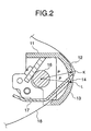
- Fig. 2 is a cross-sectional view of the platen according to the first embodiment.
- a platen 11 is formed by machining a solid material, e.g., steel, and has a curved impact surfaces 12 and 13.
- the impact surfaces 12 and 13 have flat, wide enough areas for the printhead 40 (Fig. 8) to print on the print paper.
- Slits 14 and 15 divide the impact surfaces 12 and 13 into upper parts and lower parts, respectively.
- the slit 14 is a longitudinal hole through which the multi part journal roll or 1P receipt passes.
- the slit 15 is a longitudinal hole thorough which only the 1P journal roll passes.
- the platen 11 has a shaft 16 about which the platen 11 is rotatable.
- the platen 11 has a paper guide 17 that guides the paper passing through the slits 14 and 15.
- the curvatures of the curved surfaces of the impact surfaces 12 and 13 are equal to or larger than a curvature P that passes through two points K and L immediately above and below the slits 14 and 15.
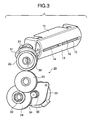
- Fig. 3 is a perspective view of a platen drive unit of the first embodiment.
- Fig. 4 is an exploded perspective view of the platen drive unit of the first embodiment.
- a platen drive unit 20 includes a boss 21, a cam lock 22, an idle gear 23, a reduction gear 24, and a drive motor 25.
- the boss 21 has two projections 26 and 27 and a rotary member 28.
- the projections 26 and 27 are fixedly supported by a frame, not shown, of a printer.
- the rotary member 28 is fixed mounted to an end of a platen shaft 16 so as to rotate together with the platen shaft 16.
- the rotary member 28 has a projection 29 formed at its one end to project therefrom. The projection 29 is off the rotational axis of the rotary portion 28.
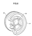
- Figs. 5 and 6 are perspective views of the cam lock.
- Fig. 7 illustrates a photo interrupter
- the cam lock 22 includes a gear 30 and a cam 31. As shown in Figs. 5 and 6, the cam 31 is formed with a cam groove 32 that describes a cam curve. The cam groove 32 receives the projection 29 of the boss 21 so that when the cam lock 22 rotates, the projection 29 slides along the cam groove 32.
- the gear 30 is in mesh with the idle gear 23.
- the idle gear 23 is in mesh with a small gear 33 of the reduction gear 24.
- a large gear 34 of the reduction gear 24 is in mesh with a motor gear 35.
- the cam lock 22, idle gear 23, reduction gear 24 are rotatably supported on the frame of the platen and the drive motor 25 is fixedly mounted to the frame.
- the platen 11 has a projection 37 formed on an end thereof to radially project.
- the photo interrupter 38 detects the rotational position of the platen 11.
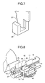
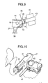
- Fig. 8 is a perspective view of the printhead and platen according to the invention.
- Fig. 9 is a side view of the printhead and platen.
- a printhead 40 is disposed to oppose the platen 11.
- the printhead 40 is carried on a self-powered carriage 41 that is guided along a carriage guide 42 to move back and forth in a traverse direction.
- a ribbon cassette 43 is mounted to the carriage 41 such that the ink ribbon extends to surround the front of the printhead 40.
- a guide plate 45 is mounted on the top of the platen 11 and guides the print paper.
- Multi-part journal paper 46 in a roll is loaded to the platen.
- the multi-part journal paper 46 enters a lower portion of the platen 11 from behind and passes through the slit 14 to the outside of the platen 11. Then, the multi-part journal paper 46 passes through a slit formed in the guide plate 45.
- the multi-part journal 46 is in intimate contact with the curved surface 12.
- Fig. 10 is a perspective view illustrating the positional relationship between the printhead and platen.
- Fig. 11 is a side view illustrates the positional relationship between the printhead and platen.
- the printhead 40 opposes another curved surface 13 of the platen 11.
- a single sheet 47 is loaded between the printhead 40 and the platen 11 together with the multi-part paper 47. It is to be noted that the printhead 40 opposes the curved surface 13 of the platen 11 and the single sheet 47 is not positioned on the multi-part journal paper 46.
- the projection 37 opens the optical path of the photo interrupter 38.
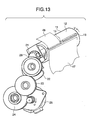
- Figs. 12 and 13 illustrate the operation of a platen driving mechanism.
- the cam lock 22 rotates counterclockwise in Fig. 13
- the projection 29 and the rotary member 28 of the boss 21 rotate in the same direction as the cam lock 22.
- the platen 11 and the shaft 16 also rotate counterclockwise, i.e., in a direction shown by arrow V so that the printhead 40 opposes the curved surface of the impact surface 13.
- the projection 37 leaves the sensor 38, which in turn causes the drive motor 25 to stop after a predetermined time, so that the platen 11 takes up a position at which the printhead 40 properly opposes the impact surface 13 of the platen 11 as shown in Figs. 10 and 11.
- the predetermined time is experimentally determined.
- the printhead 40 prints the data on the single sheet 47. There is no print paper behind the single sheet 47 and therefore the printing operation is carried out with the single sheet 47 in direct contact with the platen 11.
- the position of the platen 11 differs depending on whether printing is performed on the multi-part journal paper or on the single sheet.
- a mechanism for holding the platen 11 in position will be described with respect to the both cases. Holding the platen 11 at predetermined positions is important for two reasons; the platen tends to rotate due to its own weight and the platen also tends to rotate when the user attempts to pull out the print paper from between the platen 11 and printhead 40. Thus, it is important to maintain the platen at the predetermined positions.
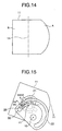
- Fig. 14 schematically illustrates an outside shape of the platen 11.
- the platen 11 has a right portion A and a left portion B with respect to a center line that passes through a rotational axis Y1.
- the portion A has a larger weight than the portion B.
- Figs. 15 and 16 illustrate the mechanism for holding the platen in position when printing is performed on the multi-part journal paper.
- Fig. 15 illustrates the position of the platen 11 when it tends to rotate due to its own weight.
- Fig. 16 illustrates the position of the platen when the user attempts to pull out the paper.
- the mechanism includes the boss 21 and the cam lock 22.
- the platen 11 will rotate about the rotational axis Y1 in a direction shown by arrow X1.
- the projection 29 of the boss 21 exerts a force f2 on the cam lock 22.
- the force f2 is resolved into a force f3 that causes the projection 29 to slide in the cam groove 32 in a direction shown by arrow X3 and a force f4 acting in a direction shown by arrow X4, i.e., perpendicular to the direction shown by arrow X3.
- the cam groove 32 is inclined at an angle such that the force f4 is greater than the force f3 at a position where the projection 29 engages the cam lock 22.
- the force f4 and the force f3 are related such that f4>f3.
- the platen 11 receives a force in a direction shown by arrow X5.
- the projection 29 exerts a force f6 acting in a direction shown by arrow X6 on the cam groove 32.
- the force f6 is resolved into a force f7 that causes the projection 29 to slide along the cam groove 32 in a direction shown by arrow X7 and a force f8 acting in a direction X8, i.e., perpendicular to the direction shown by arrow X7.
- the cam groove 32 is inclined at an angle such that the force f8 is greater than the force f7 at a position where the projection 29 engages the cam lock 22.
- the force f7 and the force f8 are related such that f8>f7.
- Figs. 17 and 18 illustrate the mechanism for holding the platen in position when printing is performed on the single sheet.
- Fig. 17 illustrates the position of the platen when it tends to rotate due to its own weight.
- Fig. 18 illustrates the position of the platen when the user attempts to pull out the paper.
- the mechanism includes the boss 21 and the cam lock 22.
- the platen 11 will rotate about the rotational axis Y1 in a direction shown by arrow X9.
- the projection 29 of the boss 21 exerts a force f10 on the cam lock 22.
- the force f10 is resolved into a force f11 that causes the projection 29 to slide in the cam groove 32 in a direction shown by arrow X11 and a force f12 acting in a direction shown by arrow X12, i.e., perpendicular to the direction shown by arrow X11.
- the cam groove 32 is inclined at an angle such that the force f12 is greater than the force fll at a position where the projection 29 engages the cam lock 22.
- the force f12 and f11 are related such that f12>f11.
- the force f11 and the force f12 are related such that f12>f11.
- the projection 29 exerts a force f14 on the cam groove 32 in a direction shown by arrow X14.
- the force f14 is resolved into a force f15 that causes the projection 29 to slide along the cam groove 32 in a direction shown by arrow X15 and a force f16 acting in a direction X16, i.e., perpendicular to the direction shown by arrow X15.
- the cam groove 32 is inclined at an angle such that the force f16 is greater than the force f15 at a position where the projection 29 engages the cam lock 22.
- the force f15 and f16 are related such that f16>f15.
- the first embodiment when printing is performed on a single sheet without the single sheet being placed on the multi-part journal paper that has been loaded to the platen 11. Moreover, the first embodiment completely eliminates the chance of pins of the printhead scratching the single sheet paper.
- Fig. 19 is a cross-sectional view of a platen according to a second embodiment.
- the second embodiment is characterized in that the multi-part journal paper is thicker than that in the first embodiment and the two impact surfaces have different curvatures.
- the platen 50 has two impact surfaces 51 and 52.
- two slits 53 are provided.
- the slits 53 extend in a longitudinal direction of the platen 50, bounding the impact surfaces 51 and 52.
- the impact surface 51 has a curvature P1 and the impact surface 52 has a curvature P2 such thatP1 ⁇ P2.
- the multi-part journal paper is loaded to the platen 50 such that the multi-part journal paper is in contact with the curved surface 51 while the single sheet is loaded to the platen 50 such that the single sheet is in contact with the impact surface 52.
- the rest of the construction of the second embodiment is the same as that of the first embodiment.
- the curvature of upper impact surface 51 smaller than that of the lower impact surface 52 offers the following advantage.
- the ordinary multi-part journal paper of down to a thickness of 0.18 mm can be printed with a head gap (e.g., range 1 is for paper thickness 0.12 mm) used for printing a single sheet, eliminating the need for adjustment of the head gap.
- the upper impact surface 51 may have different curvatures on its left half and left half.
- the platen 50 may be configured such that the left half of the impact surface 51 has a small curvature and the right half has the same curvature as the lower impact surface 52. This configuration allows the multi-impact surface journal paper to be loaded on the left half and the receipt paper to be loaded on the right half.
- Fig. 20 is an exploded perspective view of a platen according to a third embodiment.
- Fig. 21 is a cross-sectional view of the platen according to the third embodiment.
- the third embodiment is characterized in that the impact surfaces of the platen are made of different materials from the main body of the platen.
- a platen 61 has longitudinally extending grooves 62 and 63 formed therein.
- the grooves receive impact surfaces 64 and 65 therein.
- the impact surfaces 64 and 65 have surfaces of the same curvature as the main body of the platen 61 so that the impact surfaces cooperate with the main body of the platen 61 form a continuous curved surface after they have been assembled as shown in Fig. 21.
- the impact surfaces 64 and 65 are formed of a hard material, for example, steel, a different material from the platen 61.
- the body of the platen 61 has slits 66 and 67 formed therein to longitudinally extend below the groove 62.
- the slits 66 and 67 are openings through which the receipt paper and journal paper in roll form attached to the platen 61 from behind.
- the platen 61 has a shaft 68 formed in one piece construction with the platen 61 or formed as a separate shaft that extends through the platen 61.
- the platen 61 incorporates a transport path 69 along which the receipt paper or journal paper in roll form passes.
- the transport path 69 is formed in one piece construction with the platen 61. The rest of the construction is the same as the first embodiment.
- the main body of the platen 61 can be molded so that the transport path that guides the print paper in roll form can be formed in one piece construction with the main body and the number of parts can be reduced. Thus, the total manufacturing cost of the platen can be reduced.
- the impact surfaces 64 and 65 made of a hard material prevent the printing results from being low density, thereby prolonging the life of the platen 61.
- the impact surface 64 may have a smaller curvature than the impact surface 65.
- Fig. 22 is a cross-sectional view of a platen according to a fourth embodiment.
- the fourth embodiment is characterized in that the impact surface of the platen against which the print paper in roll form is loaded has a projection that is configured to the bending of the print paper and laterally extends across the platen.
- the platen 71 has impact surfaces 72 and 73 and a slit 74 formed therein between the impact surfaces 72 and 73.
- the impact surface 72 has a longitudinal projection 75 near the slit 74.
- the receipt paper 76 in roll form is loaded against the curved surface 72.
- the projection 75 is configured to the flection of the print paper 76 so that the print paper 76 is substantially in intimate contact with the projection 75.
- the fourth embodiment prevents the print paper from lifting up from the impact surface when the print paper in roll form is loaded on the platen. This in turn prevents the print paper from fluttering during printing, thereby reducing noise as well as improving print quality.
- the projection configured to the bending of the print paper may also be provided to impact surfaces of the third embodiment.
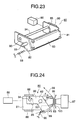
- Fig. 23 is a perspective view of a platen according to a fifth embodiment.
- Fig. 24 is a side view of the platen and printhead according to the fifth embodiment.
- Fig. 25 is an exploded perspective view illustrating the platen according to the fifth embodiment.
- the fifth embodiment is characterized in that there are provided two platens that are selectively used depending on the type of print paper.
- a platen 80 includes a first platen 81 and a second platen 82.
- the first platen 81 is U-shaped and has an impact surface 83 formed in the middle portion of the U-shape and elongated holes 84 and guide holes 85 formed in the opposed side portions of the U-shape.
- the first platen 81 is urged by a solenoid 86 (or motor) in a direction away from a printhead 87.
- a solenoid 86 or motor
- slide guides 88 that guide the movement of the first platen 81.
- the second platen 82 is also U-shaped and has an impact surface 89 in the middle portion of the U-shape and fitting holes 91 and 92 formed in the opposed side portions of the U-shape.
- the second platen 82 is assembled to the platen 80 to receive the first platen 81 such that side portions of the first platen 81 oppose those of the second platen 82.
- a shaft 93 extends through the fitting holes 91 and the elongated holes 84.
- a guide shaft 94 extends through the holes 92 an the guide holes 85.
- the shaft 93 is rotatably supported by a part of the printer, not shown.
- the shaft 93 fits into the fitting holes 91 and is fixedly assembled to the second platen 82 but is movable along the elongated holes 84.
- One end of a tension spring 96 is fastened to the underside of the second platen 82 and the other end is fastened to the main body of the printer. The spring 96 urges the second platen downward (Fig. 24).
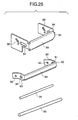
- Fig. 26 is a side view of the platen according to the fifth embodiment.
- Fig. 24 illustrates a case in which the receipt paper or journal paper is printed.
- the impact surface 83 of the first platen 81 opposes the printhead 87.
- a ribbon protector 99 and an ink ribbon 100 are disposed between the impact surface 83 and the printhead 87.
- Paper 98 in roll form passes an inner side of the second platen 82 and then passes upward through a gap between the first platen 81 and the ribbon protector 99.
- a printing operation is performed with the setup shown in Fig. 24.
- the solenoid 86 is off such that the tensile force of the spring 96 brings down the impact surface 89 of the second platen 82 and the first platen 81 moves closer to the printhead 87 to maintain a predetermined distance between the impact surface 83 and the printhead 87.
- a host apparatus when printing is performed on a single sheet, a host apparatus causes the solenoid 86 to turn on.
- the first platen 81 is pulled leftward in Fig. 24, being guided by the slide guides 88 such that the second platen 82 rotates in a direction opposite to arrow E against the tensile force of the spring 96.
- the guide shaft 94 slides downward along the guide holes 85 and the second platen 82 rotates counterclockwise about the shaft 93, so that the impact surface 89 moves upward toward the printhead 87.
- the second platen 82 stops rotating when the impact surface 89 opposes the printhead 87.
- a single sheet 101 is loaded between the impact surface 89 and the ribbon protector 99. It is to be noted that the roll paper 98 is positioned behind the impact surface 89. Thus, the single sheet does not directly contact the roll paper 98. Thereafter, upon a command from the host apparatus, the printhead 87 prints on the signal sheet 101.
- the fifth embodiment allows two platens to be selectively used depending on the types of print paper, thereby preventing the different types of print paper from contacting each other.
- the first to fifth embodiments have been described with respect to a platen having two impact surfaces. More impact surfaces may of course be employed as required.
Landscapes
- Handling Of Sheets (AREA)
Abstract
Description
Claims (13)
- A platen having an impact surface positioned to oppose a printhead so that a part of a printhead strikes a print medium loaded on the impact surface, comprising:a first impact surface (12, 51, 64, 72):a second impact surface (13, 52, 65, 73);a first path ( 14+15, 66+67, 53, 74) in which a first print medium (46, or 47) passes between said first impact surface and said second impact surface and then between said first impact surface and the printhead; anda second path in which a second print medium (46, or 47) passes between said second impact surface and the printhead.
- The platen according to Claim 1, wherein the platen (11, 50, 61, 71) is movable such that said first impact surface and said second impact surface are selectively positioned to oppose the printhead (40).
- The platen according to Claim 2, wherein the platen is rotatable about an axis (Y1) and said first impact surface has a first curvature (P1) with respect to the axis and the second impact surface has a second curvature (P2) with respect to the axis (Y1).
- The platen according to Claim 1, wherein said first impact surface has a curved surface and said second impact surface has a curved surface.
- The platen according to Claim 4, wherein the platen is rotatable about an axis (Y1) and said first impact surface has a first curvature (P1) with respect to the axis and the second impact surface has a second curvature (P2) with respect to the axis (Y1).
- A printing apparatus having an impact surface positioned to oppose a printhead so that a of a printhead strikes a print medium against the impact surface, the apparatus comprising:a plurality of impact surfaces (12, 13, 51, 52, 64, 65, 72, 73) used for printing different types of print medium supplied through different paths, each of the plurality of impact surfaces being used for a corresponding type of print medium; anda drive means (25, 86) that causes the plurality of impact surfaces to selectively oppose the printhead (40, 87) so that print data is printed on one of the different types of print medium located between a corresponding one of said plurality of impact surfaces and the printhead.
- The printing apparatus according to Claim 6, further having an opening (14+15, 66+67, 74) through which one of the different types of print medium passes, the opening being formed in a platen (11, 50, 61, 71) between adjacent ones of the plurality of impact surfaces.
- The printing apparatus according to Claim 7, wherein the plurality of impact surfaces (51, 52) have curved surfaces with different curvatures (P1, P2).
- The printing apparatus according to Claim 7, wherein the plurality of impact surfaces (64, 65) are made of a material different from other part of the platen.
- The printing apparatus according to Claim 7, further comprising means (22, 32, 29) that holds the platen (11) in position when one of the plurality of impact surfaces (12, 13) opposes the printhead (40).
- The printing apparatus according to Claim 7, wherein one (72) of the plurality of impact surfaces (72, 73) has a projection (75) that extends in a direction substantially perpendicular to a direction in which the one (72) of the different types of print medium (76) advances, the projection (75) being substantially configured to flection of the one of the different types of print medium advances.
- The printing apparatus according to Claim 6, wherein each of the plurality of impact surfaces (83, 89) is formed on each of a plurality of platens (81, 82), the plurality of platens (81, 82) being assembled such that there is a path between adjacent platens and a corresponding one of the plurality of types of print medium passes through the path.
- The printing apparatus according to Claim 12, wherein one (89) of the plurality of impact surfaces (83, 89) is driven to selectively rotate about an axis (93) to a first position where the at least one (89) of the plurality of impact surfaces directly opposes the printhead (87) and a second position where the at least one (89) of the plurality of impact surfaces does not oppose the printhead (87);
wherein the plurality of impact surfaces (83, 89) are aligned with the printhead (87) such that when the at least one (89) of the plurality of impact surfaces (83, 89) rotates from the first position to the second position, said drive means (86) causes an impact surface (83) adjacent to the at least one (89) of the plurality of impact surfaces to move closer to the printhead (87) for printing.
Applications Claiming Priority (2)
| Application Number | Priority Date | Filing Date | Title |
|---|---|---|---|
| JP2000020066A JP3727211B2 (en) | 2000-01-28 | 2000-01-28 | Platen and printing device |
| JP2000020066 | 2000-01-28 |
Publications (3)
| Publication Number | Publication Date |
|---|---|
| EP1120265A2 true EP1120265A2 (en) | 2001-08-01 |
| EP1120265A3 EP1120265A3 (en) | 2002-07-24 |
| EP1120265B1 EP1120265B1 (en) | 2004-06-02 |
Family
ID=18546683
Family Applications (1)
| Application Number | Title | Priority Date | Filing Date |
|---|---|---|---|
| EP01101732A Expired - Lifetime EP1120265B1 (en) | 2000-01-28 | 2001-01-25 | Platen and printing apparatus |
Country Status (5)
| Country | Link |
|---|---|
| US (1) | US6412995B2 (en) |
| EP (1) | EP1120265B1 (en) |
| JP (1) | JP3727211B2 (en) |
| CN (1) | CN1304202C (en) |
| DE (1) | DE60103566T2 (en) |
Cited By (2)
| Publication number | Priority date | Publication date | Assignee | Title |
|---|---|---|---|---|
| EP1867490A1 (en) | 2006-06-14 | 2007-12-19 | Alps Electric Co., Ltd. | Platen and printer |
| EP1872957A3 (en) * | 2006-06-29 | 2008-11-05 | Toshiba Tec Kabushiki Kaisha | Printer |
Families Citing this family (7)
| Publication number | Priority date | Publication date | Assignee | Title |
|---|---|---|---|---|
| JP4756730B2 (en) * | 2000-09-07 | 2011-08-24 | 東芝テック株式会社 | Stamp stand support device |
| US6739503B1 (en) * | 2003-02-26 | 2004-05-25 | Ncr Corporation | Apparatus for use in a self-service terminal and a method of processing a financial instrument at a self-service terminal |
| CN101434151B (en) * | 2007-11-13 | 2010-10-13 | 旭丽电子(广州)有限公司 | Heat sublimation printer |
| JP4936335B2 (en) * | 2007-12-28 | 2012-05-23 | シチズン・システムズ株式会社 | Printer |
| JP4762291B2 (en) | 2008-10-17 | 2011-08-31 | 株式会社沖データ | Printing device |
| JP5823743B2 (en) * | 2011-06-22 | 2015-11-25 | 富士通コンポーネント株式会社 | Thermal printer |
| JP6462420B2 (en) * | 2015-02-27 | 2019-01-30 | セイコーインスツル株式会社 | Printing unit and thermal printer |
Family Cites Families (12)
| Publication number | Priority date | Publication date | Assignee | Title |
|---|---|---|---|---|
| US1309332A (en) * | 1919-07-08 | Art osi ciialxfing hose-lines | ||
| US3854563A (en) * | 1973-06-25 | 1974-12-17 | Ibm | Arcuate printer |
| JPS59227478A (en) * | 1983-06-10 | 1984-12-20 | Janome Sewing Mach Co Ltd | Color printer |
| JPS6080940U (en) * | 1983-11-10 | 1985-06-05 | 蛇の目ミシン工業株式会社 | Ink-impregnated platen of ink platen printer |
| JPS6189065A (en) * | 1984-10-08 | 1986-05-07 | Nec Corp | Dot matrix printer |
| US4984914A (en) * | 1988-03-28 | 1991-01-15 | Tpshio Hayakawa | Multi-task printer |
| JPH02179770A (en) * | 1988-12-30 | 1990-07-12 | Oki Electric Ind Co Ltd | Paper feeder in printer |
| US4943814A (en) * | 1989-03-23 | 1990-07-24 | Columbia Research And Manufacturing Company | Computer controllable multi-purpose platen thermal printer |
| JPH05124274A (en) * | 1991-11-05 | 1993-05-21 | Seiko Epson Corp | Printer |
| JPH06238965A (en) * | 1993-02-19 | 1994-08-30 | Brother Ind Ltd | Impact dot printer |
| JPH09286148A (en) * | 1996-04-24 | 1997-11-04 | Tec Corp | Printer |
| US6261008B1 (en) * | 1998-02-12 | 2001-07-17 | Seiko Epson Corporation | Platen mechanism, a printing device with the platen mechanism, and a method of controlling the printing device |
-
2000
- 2000-01-28 JP JP2000020066A patent/JP3727211B2/en not_active Expired - Fee Related
-
2001
- 2001-01-25 DE DE60103566T patent/DE60103566T2/en not_active Expired - Lifetime
- 2001-01-25 US US09/771,298 patent/US6412995B2/en not_active Expired - Lifetime
- 2001-01-25 EP EP01101732A patent/EP1120265B1/en not_active Expired - Lifetime
- 2001-01-27 CN CNB011116420A patent/CN1304202C/en not_active Expired - Fee Related
Cited By (3)
| Publication number | Priority date | Publication date | Assignee | Title |
|---|---|---|---|---|
| EP1867490A1 (en) | 2006-06-14 | 2007-12-19 | Alps Electric Co., Ltd. | Platen and printer |
| EP1872957A3 (en) * | 2006-06-29 | 2008-11-05 | Toshiba Tec Kabushiki Kaisha | Printer |
| EP2085230A1 (en) * | 2006-06-29 | 2009-08-05 | Toshiba Tec Kabushiki Kaisha | Printer |
Also Published As
| Publication number | Publication date |
|---|---|
| EP1120265A3 (en) | 2002-07-24 |
| DE60103566D1 (en) | 2004-07-08 |
| DE60103566T2 (en) | 2005-06-30 |
| EP1120265B1 (en) | 2004-06-02 |
| US6412995B2 (en) | 2002-07-02 |
| JP3727211B2 (en) | 2005-12-14 |
| US20010010775A1 (en) | 2001-08-02 |
| JP2001205871A (en) | 2001-07-31 |
| CN1306906A (en) | 2001-08-08 |
| CN1304202C (en) | 2007-03-14 |
Similar Documents
| Publication | Publication Date | Title |
|---|---|---|
| CN102825923B (en) | Platen gap adjustment mechanism and printer | |
| US7083245B2 (en) | Recording apparatus | |
| EP1120265B1 (en) | Platen and printing apparatus | |
| EP1683643B1 (en) | Read/write processing device with paper release on jam detection | |
| EP0853003A2 (en) | Printer | |
| KR20000017454A (en) | Printer | |
| EP1707515B1 (en) | Medium edge guide in medium feeder and recording apparatus or liquid ejecting apparatus incorporating the same | |
| JP2011110812A (en) | Recording device and recording medium supplying structure for the recording device | |
| JP2001105383A (en) | Sheet cutting device | |
| JP4078241B2 (en) | Recording device | |
| US20070020010A1 (en) | Ink ribbon cassette | |
| US7001017B2 (en) | Drive roller releasing apparatus for ink-jet printer | |
| JPH10139235A (en) | Discharge mechanism of recorder | |
| JP2008080649A (en) | Conveying mechanism and recording apparatus having the same | |
| JP7830997B2 (en) | Sheet transport device and image recording device equipped with sheet transport device | |
| JP4628859B2 (en) | Thermal head positioning mechanism and thermal printer | |
| US7289134B2 (en) | Thermal printer including a plurality of recording units | |
| JP2015054407A (en) | Recording apparatus | |
| JP4499048B2 (en) | Medium transport mechanism and image forming apparatus | |
| JP3684993B2 (en) | Dot impact type recording device | |
| JPH08142443A (en) | Thermal transfer printer | |
| JP2001030593A (en) | Impact dot printer and its control method | |
| JP3758458B2 (en) | Recording device | |
| JP2006043893A (en) | Recording device | |
| JP2002002056A (en) | Printer |
Legal Events
| Date | Code | Title | Description |
|---|---|---|---|
| PUAI | Public reference made under article 153(3) epc to a published international application that has entered the european phase |
Free format text: ORIGINAL CODE: 0009012 |
|
| AK | Designated contracting states |
Kind code of ref document: A2 Designated state(s): AT BE CH CY DE DK ES FI FR GB GR IE IT LI LU MC NL PT SE TR |
|
| AX | Request for extension of the european patent |
Free format text: AL;LT;LV;MK;RO;SI |
|
| PUAL | Search report despatched |
Free format text: ORIGINAL CODE: 0009013 |
|
| AK | Designated contracting states |
Kind code of ref document: A3 Designated state(s): AT BE CH CY DE DK ES FI FR GB GR IE IT LI LU MC NL PT SE TR |
|
| AX | Request for extension of the european patent |
Free format text: AL;LT;LV;MK;RO;SI |
|
| 17P | Request for examination filed |
Effective date: 20030120 |
|
| 17Q | First examination report despatched |
Effective date: 20030303 |
|
| AKX | Designation fees paid |
Designated state(s): DE FR GB |
|
| GRAP | Despatch of communication of intention to grant a patent |
Free format text: ORIGINAL CODE: EPIDOSNIGR1 |
|
| GRAS | Grant fee paid |
Free format text: ORIGINAL CODE: EPIDOSNIGR3 |
|
| GRAA | (expected) grant |
Free format text: ORIGINAL CODE: 0009210 |
|
| AK | Designated contracting states |
Kind code of ref document: B1 Designated state(s): DE FR GB |
|
| REG | Reference to a national code |
Ref country code: GB Ref legal event code: FG4D |
|
| REF | Corresponds to: |
Ref document number: 60103566 Country of ref document: DE Date of ref document: 20040708 Kind code of ref document: P |
|
| REG | Reference to a national code |
Ref country code: IE Ref legal event code: FG4D |
|
| ET | Fr: translation filed | ||
| PLBE | No opposition filed within time limit |
Free format text: ORIGINAL CODE: 0009261 |
|
| STAA | Information on the status of an ep patent application or granted ep patent |
Free format text: STATUS: NO OPPOSITION FILED WITHIN TIME LIMIT |
|
| 26N | No opposition filed |
Effective date: 20050303 |
|
| REG | Reference to a national code |
Ref country code: FR Ref legal event code: PLFP Year of fee payment: 16 |
|
| REG | Reference to a national code |
Ref country code: FR Ref legal event code: PLFP Year of fee payment: 17 |
|
| REG | Reference to a national code |
Ref country code: FR Ref legal event code: PLFP Year of fee payment: 18 |
|
| PGFP | Annual fee paid to national office [announced via postgrant information from national office to epo] |
Ref country code: FR Payment date: 20181213 Year of fee payment: 19 |
|
| PGFP | Annual fee paid to national office [announced via postgrant information from national office to epo] |
Ref country code: DE Payment date: 20190115 Year of fee payment: 19 Ref country code: GB Payment date: 20190123 Year of fee payment: 19 |
|
| REG | Reference to a national code |
Ref country code: DE Ref legal event code: R119 Ref document number: 60103566 Country of ref document: DE |
|
| GBPC | Gb: european patent ceased through non-payment of renewal fee |
Effective date: 20200125 |
|
| PG25 | Lapsed in a contracting state [announced via postgrant information from national office to epo] |
Ref country code: DE Free format text: LAPSE BECAUSE OF NON-PAYMENT OF DUE FEES Effective date: 20200801 Ref country code: GB Free format text: LAPSE BECAUSE OF NON-PAYMENT OF DUE FEES Effective date: 20200125 Ref country code: FR Free format text: LAPSE BECAUSE OF NON-PAYMENT OF DUE FEES Effective date: 20200131 |