EP1120182A2 - The drive pulley and the wire saw equipment using it and the cutting method - Google Patents
The drive pulley and the wire saw equipment using it and the cutting method Download PDFInfo
- Publication number
- EP1120182A2 EP1120182A2 EP01100164A EP01100164A EP1120182A2 EP 1120182 A2 EP1120182 A2 EP 1120182A2 EP 01100164 A EP01100164 A EP 01100164A EP 01100164 A EP01100164 A EP 01100164A EP 1120182 A2 EP1120182 A2 EP 1120182A2
- Authority
- EP
- European Patent Office
- Prior art keywords
- wire saw
- drive pulley
- pulley
- rotor
- winded
- Prior art date
- Legal status (The legal status is an assumption and is not a legal conclusion. Google has not performed a legal analysis and makes no representation as to the accuracy of the status listed.)
- Withdrawn
Links
- 238000000034 method Methods 0.000 title claims description 8
- 239000000463 material Substances 0.000 claims abstract description 23
- 239000002245 particle Substances 0.000 claims abstract description 13
- 229910003460 diamond Inorganic materials 0.000 claims abstract description 6
- 239000010432 diamond Substances 0.000 claims abstract description 6
- 230000005611 electricity Effects 0.000 claims abstract description 3
- 239000000203 mixture Substances 0.000 description 6
- 238000010586 diagram Methods 0.000 description 3
- 229910052796 boron Inorganic materials 0.000 description 1
- 239000011248 coating agent Substances 0.000 description 1
- 238000000576 coating method Methods 0.000 description 1
- KPLQYGBQNPPQGA-UHFFFAOYSA-N cobalt samarium Chemical compound [Co].[Sm] KPLQYGBQNPPQGA-UHFFFAOYSA-N 0.000 description 1
- 230000001143 conditioned effect Effects 0.000 description 1
- 238000005516 engineering process Methods 0.000 description 1
- 230000002787 reinforcement Effects 0.000 description 1
- 239000011347 resin Substances 0.000 description 1
- 229920005989 resin Polymers 0.000 description 1
- 229910000938 samarium–cobalt magnet Inorganic materials 0.000 description 1
- 238000005245 sintering Methods 0.000 description 1
- 238000005303 weighing Methods 0.000 description 1
- 238000004804 winding Methods 0.000 description 1
Images


Classifications
-
- B—PERFORMING OPERATIONS; TRANSPORTING
- B23—MACHINE TOOLS; METAL-WORKING NOT OTHERWISE PROVIDED FOR
- B23D—PLANING; SLOTTING; SHEARING; BROACHING; SAWING; FILING; SCRAPING; LIKE OPERATIONS FOR WORKING METAL BY REMOVING MATERIAL, NOT OTHERWISE PROVIDED FOR
- B23D57/00—Sawing machines or sawing devices not covered by one of the preceding groups B23D45/00 - B23D55/00
- B23D57/003—Sawing machines or sawing devices working with saw wires, characterised only by constructional features of particular parts
- B23D57/0053—Sawing machines or sawing devices working with saw wires, characterised only by constructional features of particular parts of drives for saw wires; of wheel mountings; of wheels
-
- B—PERFORMING OPERATIONS; TRANSPORTING
- B23—MACHINE TOOLS; METAL-WORKING NOT OTHERWISE PROVIDED FOR
- B23D—PLANING; SLOTTING; SHEARING; BROACHING; SAWING; FILING; SCRAPING; LIKE OPERATIONS FOR WORKING METAL BY REMOVING MATERIAL, NOT OTHERWISE PROVIDED FOR
- B23D61/00—Tools for sawing machines or sawing devices; Clamping devices for these tools
- B23D61/18—Sawing tools of special type, e.g. wire saw strands, saw blades or saw wire equipped with diamonds or other abrasive particles in selected individual positions
Definitions
- the drive pulley and the wire saw equipment using it and the cutting method using it and the cutting method.
- This invention relates to the drive pulley and the wire saw equipment using it and the cutting method which make it run wire saw used in case that the concrete structures such as a building and a bridge are cut.
- the wire saw equipment using wire saw which has the ring part which sintered abrasive particles openly interval in the wire rod of long pictures, such as a wire gave resin coating or rubber covering.
- This wire saw equipment rotate the pulley by which wire saw was winded by the electric gear motor, engine, or the oil pressure motor, and cuts a cut materials by this wire saw.
- a mark 1 is a wire saw equipment.
- This wire saw equipment 1 has base stand 2 installed in floor face, the support 3 set up possible to move in the direction of long length on this base stand 2, the drive equipment 4 supported possible to rise and fall to this support 3, and wire saw 5 it runs with this drive equipment 4.
- the drive equipment 4 has the electric gear motor 6 and the pulley 7 connected to this electric gear motor 6, and wire saw 5 is winded to this pulley 7.
- the wire saw 5 is guided and winded by two or more guide pulleys 8 in the cut part of cut material A such as a bridge pier.
- the pulley 7 is rotated by making the electric gear motor 6 drive, and it is made to run wire saw 5 in the condition that the predetermined tension is always given to wire saw 5. If it does in this way, the cut material A will be cut by the ring part of wire saw 5 by running, while wire saw 5 contacts the cut material A.
- This invention was made in view of the above mentioned situation, it aims to offer a drive pulley which is a compact and is possible to rotate in high speed, and to offer a wire saw equipment with a compact, light-weight, high performance, and low noise using this drive pulley, and also to offer the cutting method.
- the drive pulley of claim 1 has a stator which is a fixed axis and an annular rotor prepared in the perimeter of this stator, and a pulley part established in the perimeter of this rotor in which a wire rod is winded in the direction of perimeter. It is characterized to make the wire rod winded in a pulley part through above mentioned rotor rotate to above mentioned stator by turning on electricity.
- the drive pulley of claim 2 is characterized that the attachment and detachment to above mentioned rotor are possible for the above mentioned pulley part in the drive pulley of claim 1.
- the wire saw equipment of claim 3 is the wire saw equipment which cuts the above mentioned work material by making it run, contacting wire saw which consists of a wire rod with which abrasive particles are prepared.
- the drive equipment which makes it run the above mentioned wire saw consists of a drive pulley of claim 1 or claim 2, it is characterized by making the above mentioned wire saw run by rotating above mentioned rotor through the winding the above mentioned wire saw by the pulley part of this drive pulley.
- a wire saw equipment in the claim 4 it is characterized that two or more drive pulley mentioned above are prepared, and above mentioned wire saw is winded in these plural drive pulley and is arranged in a predetermined position.
- wire saw is winded and arranged in two or more drive pulleys, it is possible to make the wire saw run in a condition of good stability and powerfully without it makes wire saw slip by these drive pulleys, and it becomes further high speedy and also miniaturization of the whole equipment is attained.
- the wire saw equipment of claim 5 is characterized that above mentioned wire saw in a wire saw equipment of claim 3 or claim 4 is prepared opening an interval the ring portion which is sintered diamond abrasive particles as a abrasive particles to the above mentioned wire rod.
- wire saw which runs by a drive pulley ring parts which diamond abrasive particles as an abrasive particles is sintered to the wire rod, the cut materials is cut very easily and good state by ring part of wire saw which runs in a high speed by a drive pulley.
- the cutting method of claim 6 is characterized that above mentioned cut material is cut by making above mentioned wire saw run through the rotation of above mentioned rotor of above mentioned drive pulley, straining by the wind a part of above mentioned wire saw which is winded to above mentioned drive pulley which consists of wire saw equipment of claim 3 ⁇ 5 to above mentioned cut material.
- Figure 1 is the perspective diagram of the wire saw equipment in the middle of the cutting work explaining composition and structure of the wire saw equipment using the drive pulley of the enforcement form of this invention and it.
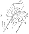
- Figure 2 is the perspective diagram of a drive pulley explaining the composition and structure of a drive pulley of this invention.
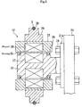
- Figure 3 is the sectional view of a drive pulley explaining the composition and structure of a drive pulley of this invention.
- Figure 4 is the perspective diagram of wire saw equipment explaining the composition and structure of wire saw equipment.
- a mark 11 is the wire saw equipment of this enforcement form.
- the drive pulley 12 is supported by the support 3 and the drive equipment 4 is constituted by this drive pulley 12 in this wire saw equipment 11.
- the drive pulley 12 has a stator 21 and the rotor 22 established in the perimeter side of this stator 21, and the flange 21a established prepared in the end portion of stator 21 is fixed jointly by bolt to the bracket 23 fixed to the support 3.
- the bearing 25 is prepared between stator 21 and rotor 22, and the rotor 22 is supported possible to rotate by these bearing 25, and the power of the direction of thrust and the power of the radial direction acting on rotor 22 are received.
- a magnet 26 is prepared in the inner side of rotor22, and the coil 27 is prepared in perimeter side of stator 21. And rotor 22 which has a magnet 26 becomes to be rotated by supplying the current to a coil 27. That is, this drive pulley has the composition so that the rotor 22 which is a ling-like rotator becomes to be rotated in perimeter side of stator 21 used as fixed axis.
- the magnet of neodium-iron-boron system and or the magnet of samarium-cobalt system which occur strongly magnetic force as a magnet 26 are used.
- the pulley part 29 in which the groove portion 28 is formed in the direction of a circumference covering the perimeter side is attached possible to attach or detach in perimeter side of rotor 22, and the wire saw 5 is arranged and winded in a groove portion 28 of this pulley part 29.
- the wire saw equipment 11 using the drive pulley 12 which is constituted as mentioned above and it, if the drive current is supplied to stator 21 of the drive pulley 12, the rotor 22 will rotate at high speed.
- the wire saw 5 arranged at the groove portion 28 of the pulley part 29 which is prepared in perimeter side of this rotor 22 runs at high speed, and by this, the cut material A which this wire saw 5 is winded by predetermined tension is cut in ring part 5a which is the sintering part of diamond abrasive particle of wire saw 5 and the cut material is cut down.
- the improvement in the speed of line speed of wire saw 5 can be easily attained without using the pulley of the large diameter, and the noise can also be reduced sharply.
- the attaching and detaching of the pulley part 29 by which wire saw 5 is winded are enabled, the pulley part 29 from which an outer diameter is different according to the conditions such as line speed etc. which is demanded can be changed, and the flexibility can be raised.
- wire saw 5 it runs by the drive pulley 12 has ring part 5a which sintered diamond abrasive particle as abrasive particle to the wire rod, ring part 5a of wire saw 5 in which a high speed run is carried out by the drive pulley 12 can cut the cut material A very easily and in good state.
- annular rotor 22 established in the perimeter of stator 21 which is a fixed axis is rotated directly and the drive pulley 12 which makes it run wire saw 5 winded in the perimeter is used, line speed of wire saw 5 can be easily made high speed without using the pulley of the large diameter as comparison with the case where engine , an oil pressure motor, or an electric gear motor, and the cut material A can be easily cut in low noise, and miniaturization can be attained.
- the magnet 26 is prepared in rotor 22 in the above-mentioned example, it is good also as the structure which could prepare the coil in the rotor 22 side and the magnet could be prepared in the stator 21 side , or prepared the coil in both stator 21 and rotor 22. Moreover, which form of a brush or brush-less is sufficient as the drive pulley 12 which has these stator 21 and rotor 22.
- wire saw 5 as a wire rod it is made to run by the drive pulley 12
- a belt or chains such as a common belt and V belt, etc. are sufficient
- the pulley part 29 is exchanged by the thing of various form ( in the case of a chain, it is a sprocket ) in these cases according to the wire rod it is made to run, for example.
- the drive pulley 12 was formed in the drive equipment 4 and it was made to run wire saw 5 by this drive pulley 12 in above mentioned wire saw equipment 11, this wire saw is winded and arranged to two or more drive pulley 12 and it may be made to make it run wire saw 5 by the drive pulley 12 of these plurality. That is, in the above-mentioned wire saw equipment 11, you may be made to use the drive pulley 12 as a guide pulley 8 which guides the wire saw 5 to the cut part of the cut material A.
Landscapes
- Engineering & Computer Science (AREA)
- Mechanical Engineering (AREA)
- Finish Polishing, Edge Sharpening, And Grinding By Specific Grinding Devices (AREA)
- Processing Of Stones Or Stones Resemblance Materials (AREA)
- Sawing (AREA)
- Pulleys (AREA)
Abstract
Description
Claims (6)
- The drive pulley comprised of stator which is a fixed axis, annular rotor prepared in the perimeter of this stator and the pulley part prepared in this rotor, in which a wire rod is winded to the perimeter, and characterized by making it run the wire rod winded to the pulley part by rotating the rotor to the stator by turning on electricity.
- the drive pulley of claim 1 characterized that the above-mentioned pulley part is enabled the attaching and detaching to the above-mentioned rotor.
- The wire saw equipment which cuts the cut material by making it run contacting wire saw consisting of the line rod prepared abrasive particle to the cut material, and the wire saw equipment characterized that the drive equipment running the above-mentioned wire saw consists of the drive pulley of claim 1 and claim 2, the above-mentioned wire saw is winded to the pulley part of this drive pulley, and it make it run the wire saw by making the rotor rotating.
- The wire saw equipment of claim 3 characterized that above-mentioned drive pulley is prepared two or more, and above-mentioned wire saw is winded to the drive pulley of these plurality and arranged in the predetermined position.
- The wire saw equipment of claim 3 or claim 4 characterized that the above-mentioned wire saw has the ring parts sintered diamond abrasive particle as abrasive particle preparing opening an interval in the above-mentioned wire rod.
- The cutting method characterized that a part of wire saw winded drive pulley which constitute wire saw equipment described in any one claim of claim 3 to 5 is winded to the cut material and make it straining and running the wire saw by rotating the rotor of drive pulley and cut the cut material.
Applications Claiming Priority (4)
| Application Number | Priority Date | Filing Date | Title |
|---|---|---|---|
| JP2000019177 | 2000-01-27 | ||
| JP2000019177 | 2000-01-27 | ||
| JP2000370193A JP2001277093A (en) | 2000-01-27 | 2000-12-05 | Drive pulley, wire saw device using the same, and cutting method |
| JP2000370193 | 2000-12-05 |
Publications (2)
| Publication Number | Publication Date |
|---|---|
| EP1120182A2 true EP1120182A2 (en) | 2001-08-01 |
| EP1120182A3 EP1120182A3 (en) | 2004-02-04 |
Family
ID=26584322
Family Applications (1)
| Application Number | Title | Priority Date | Filing Date |
|---|---|---|---|
| EP01100164A Withdrawn EP1120182A3 (en) | 2000-01-27 | 2001-01-16 | The drive pulley and the wire saw equipment using it and the cutting method |
Country Status (6)
| Country | Link |
|---|---|
| US (1) | US20010029939A1 (en) |
| EP (1) | EP1120182A3 (en) |
| JP (1) | JP2001277093A (en) |
| KR (1) | KR20010078115A (en) |
| CN (1) | CN1262380C (en) |
| TW (1) | TW480311B (en) |
Cited By (3)
| Publication number | Priority date | Publication date | Assignee | Title |
|---|---|---|---|---|
| WO2007024136A1 (en) * | 2005-08-22 | 2007-03-01 | Global Tool Management As | Wire drive wheel for a diamond wire machine |
| WO2014026682A1 (en) * | 2012-08-14 | 2014-02-20 | Schaeffler Technologies AG & Co. KG | Belt pulley arrangement for a belt drive for driving auxiliary units of a motor vehicle and method for driving an auxiliary unit of a motor vehicle connected via a belt pulley arrangement |
| WO2014127755A1 (en) * | 2013-02-20 | 2014-08-28 | Schaeffler Technologies AG & Co. KG | Belt pulley arrangement for a belt drive for driving auxiliary units of a motor vehicle, and a method for driving a motor vehicle auxiliary unit that is connected by means of a belt pulley arrangement |
Families Citing this family (13)
| Publication number | Priority date | Publication date | Assignee | Title |
|---|---|---|---|---|
| KR20030025140A (en) * | 2001-09-19 | 2003-03-28 | 정희이앤지(주) | An angle of intersection an underwater a support a fabric cutting wiresaw zigequipment |
| KR100785512B1 (en) * | 2004-07-16 | 2007-12-13 | 이화다이아몬드공업 주식회사 | Bead and Wire Saw for Wire Saw |
| DE102007019566B4 (en) | 2007-04-25 | 2012-11-29 | Siltronic Ag | Wire guide roller for wire saw |
| KR100898151B1 (en) * | 2008-10-08 | 2009-05-19 | 장은영 | Eco-friendly wire saw cutting device and cutting method using the same |
| EP2505290B1 (en) * | 2011-03-28 | 2014-11-12 | Alstom Technology Ltd | Device and method for cutting the end winding of an electric machine |
| KR101211185B1 (en) * | 2012-01-11 | 2012-12-12 | 이화다이아몬드공업 주식회사 | Propeller riser cutting apparatus using wire saw |
| US8833358B1 (en) * | 2012-05-16 | 2014-09-16 | John J. Robinson, III | Concrete saw system |
| CN103821891A (en) * | 2014-03-04 | 2014-05-28 | 太仓云联信息科技有限公司 | Synchronous pulley mounting plate |
| CN106042202A (en) * | 2016-06-22 | 2016-10-26 | 广州市昊志机电股份有限公司 | Wafer cutting machine |
| NO342783B1 (en) * | 2016-08-12 | 2018-08-06 | 1Diamond As | Magazine wire saw |
| KR101858428B1 (en) * | 2016-11-11 | 2018-05-16 | 삼익티에이치케이 주식회사 | Low inertia pulley for wire saws |
| NO345448B1 (en) | 2018-01-30 | 2021-02-01 | 1Diamond As | Inclined cut GBS leg |
| CN117162282B (en) * | 2023-08-15 | 2024-08-09 | 中铁北京工程局集团城市轨道交通工程有限公司 | Rope saw cutting device |
Family Cites Families (4)
| Publication number | Priority date | Publication date | Assignee | Title |
|---|---|---|---|---|
| JPH049138Y2 (en) * | 1986-04-12 | 1992-03-06 | ||
| US4853567A (en) * | 1987-03-02 | 1989-08-01 | Yokogawa Electric Corporation | Direct drive motor |
| JPH04183571A (en) * | 1990-11-13 | 1992-06-30 | Auto Kiden Kk | Diamond wire saw and use method thereof |
| JPH0929608A (en) * | 1995-07-25 | 1997-02-04 | Tokyo Seimitsu Co Ltd | Wire reel drive structure of wire saw |
-
2000
- 2000-12-05 JP JP2000370193A patent/JP2001277093A/en not_active Withdrawn
- 2000-12-27 TW TW089127997A patent/TW480311B/en not_active IP Right Cessation
-
2001
- 2001-01-02 US US09/750,761 patent/US20010029939A1/en not_active Abandoned
- 2001-01-16 EP EP01100164A patent/EP1120182A3/en not_active Withdrawn
- 2001-01-22 CN CNB011030755A patent/CN1262380C/en not_active Expired - Fee Related
- 2001-01-27 KR KR1020010003908A patent/KR20010078115A/en not_active Withdrawn
Cited By (6)
| Publication number | Priority date | Publication date | Assignee | Title |
|---|---|---|---|---|
| WO2007024136A1 (en) * | 2005-08-22 | 2007-03-01 | Global Tool Management As | Wire drive wheel for a diamond wire machine |
| WO2014026682A1 (en) * | 2012-08-14 | 2014-02-20 | Schaeffler Technologies AG & Co. KG | Belt pulley arrangement for a belt drive for driving auxiliary units of a motor vehicle and method for driving an auxiliary unit of a motor vehicle connected via a belt pulley arrangement |
| CN104995434A (en) * | 2012-08-14 | 2015-10-21 | 舍弗勒技术股份两合公司 | Pulley device for a belt drive for driving accessories of a motor vehicle and method for driving accessories of a motor vehicle connected via a pulley device |
| CN104995434B (en) * | 2012-08-14 | 2017-08-15 | 舍弗勒技术股份两合公司 | Pulley device and method for driving an accessory connected to a pulley device |
| US9915198B2 (en) | 2012-08-14 | 2018-03-13 | Schaeffler Technologies AG & Co., KG | Belt pulley arrangement for a belt drive for driving auxiliary units of a motor vehicle and method for driving an auxiliary unit of a motor vehicle connected via a belt pulley arrangement |
| WO2014127755A1 (en) * | 2013-02-20 | 2014-08-28 | Schaeffler Technologies AG & Co. KG | Belt pulley arrangement for a belt drive for driving auxiliary units of a motor vehicle, and a method for driving a motor vehicle auxiliary unit that is connected by means of a belt pulley arrangement |
Also Published As
| Publication number | Publication date |
|---|---|
| US20010029939A1 (en) | 2001-10-18 |
| CN1262380C (en) | 2006-07-05 |
| EP1120182A3 (en) | 2004-02-04 |
| JP2001277093A (en) | 2001-10-09 |
| KR20010078115A (en) | 2001-08-20 |
| CN1312144A (en) | 2001-09-12 |
| TW480311B (en) | 2002-03-21 |
Similar Documents
| Publication | Publication Date | Title |
|---|---|---|
| US20010029939A1 (en) | Drive pulley and the wire saw equipment using it and the cutting method | |
| CN100376465C (en) | Device containing pulley and electric motor special for elevator | |
| BR9402571A (en) | Lift and engine machinery for the same | |
| KR100740390B1 (en) | Lifting gear | |
| EP1942571A1 (en) | Motor with two rotors and apparatus with the same | |
| MY122874A (en) | Motor and light amount adjusting apparatus | |
| GB0329607D0 (en) | Electric motor | |
| CN117699614A (en) | Hoisting device of elevator and elevator | |
| CN112260133B (en) | Rope binding device | |
| WO2002097279A1 (en) | Method for balancing a fan blade wheel | |
| US20210391106A1 (en) | Magnetizing permanent magnets | |
| CN1440109A (en) | Miniature motor and its manufacture | |
| CN1794541A (en) | turbo generator | |
| US5299552A (en) | Method and apparatus for cutting circular opening in structure | |
| US4911606A (en) | Method for providing rotor windings | |
| FR2919971A1 (en) | ELECTRIC GENERATOR AND INSTALLATION COMPRISING A LIGHTING TOWER SUPPLIED BY SUCH A GENERATOR | |
| CN211004016U (en) | Cable reel | |
| CN103534912A (en) | Electrical motor for a submersible machine | |
| CN2482763Y (en) | Conic air-gap regulating generator | |
| US5875999A (en) | Cables suspension devices | |
| CN223161151U (en) | General stone material wire cutting machine | |
| CN205565988U (en) | Motor spindle | |
| CN212197870U (en) | Aeronet tightening device | |
| CN213456094U (en) | Rotating machinery fault simulation test bed | |
| CN217540429U (en) | a lighting assembly |
Legal Events
| Date | Code | Title | Description |
|---|---|---|---|
| PUAI | Public reference made under article 153(3) epc to a published international application that has entered the european phase |
Free format text: ORIGINAL CODE: 0009012 |
|
| AK | Designated contracting states |
Kind code of ref document: A2 Designated state(s): AT BE CH CY DE DK ES FI FR GB GR IE IT LI LU MC NL PT SE TR |
|
| AX | Request for extension of the european patent |
Free format text: AL;LT;LV;MK;RO;SI |
|
| PUAL | Search report despatched |
Free format text: ORIGINAL CODE: 0009013 |
|
| AK | Designated contracting states |
Kind code of ref document: A3 Designated state(s): AT BE CH CY DE DK ES FI FR GB GR IE IT LI LU MC NL PT SE TR |
|
| AX | Request for extension of the european patent |
Extension state: AL LT LV MK RO SI |
|
| AKX | Designation fees paid | ||
| REG | Reference to a national code |
Ref country code: DE Ref legal event code: 8566 |
|
| STAA | Information on the status of an ep patent application or granted ep patent |
Free format text: STATUS: THE APPLICATION IS DEEMED TO BE WITHDRAWN |
|
| 18D | Application deemed to be withdrawn |
Effective date: 20040803 |