EP1119711B1 - Improved motor/spool interface for direct drive servovalve - Google Patents
Improved motor/spool interface for direct drive servovalve Download PDFInfo
- Publication number
- EP1119711B1 EP1119711B1 EP99916490A EP99916490A EP1119711B1 EP 1119711 B1 EP1119711 B1 EP 1119711B1 EP 99916490 A EP99916490 A EP 99916490A EP 99916490 A EP99916490 A EP 99916490A EP 1119711 B1 EP1119711 B1 EP 1119711B1
- Authority
- EP
- European Patent Office
- Prior art keywords
- sleeve
- cylindrical sleeve
- direct drive
- spool
- ball
- Prior art date
- Legal status (The legal status is an assumption and is not a legal conclusion. Google has not performed a legal analysis and makes no representation as to the accuracy of the status listed.)
- Expired - Lifetime
Links
- 239000000463 material Substances 0.000 claims description 5
- 239000000853 adhesive Substances 0.000 claims description 4
- 230000001070 adhesive effect Effects 0.000 claims description 4
- 229920006351 engineering plastic Polymers 0.000 claims description 2
- 230000008878 coupling Effects 0.000 description 11
- 238000010168 coupling process Methods 0.000 description 11
- 238000005859 coupling reaction Methods 0.000 description 11
- 239000012530 fluid Substances 0.000 description 6
- 229920005989 resin Polymers 0.000 description 5
- 239000011347 resin Substances 0.000 description 5
- 238000004519 manufacturing process Methods 0.000 description 3
- 229910052751 metal Inorganic materials 0.000 description 3
- 239000002184 metal Substances 0.000 description 3
- 239000004033 plastic Substances 0.000 description 3
- 229920003023 plastic Polymers 0.000 description 3
- 239000004962 Polyamide-imide Substances 0.000 description 2
- 239000003822 epoxy resin Substances 0.000 description 2
- 238000003780 insertion Methods 0.000 description 2
- 230000037431 insertion Effects 0.000 description 2
- 238000000465 moulding Methods 0.000 description 2
- 229920002312 polyamide-imide Polymers 0.000 description 2
- 229920000647 polyepoxide Polymers 0.000 description 2
- 229920000642 polymer Polymers 0.000 description 2
- 229910001220 stainless steel Inorganic materials 0.000 description 2
- 239000010935 stainless steel Substances 0.000 description 2
- UONOETXJSWQNOL-UHFFFAOYSA-N tungsten carbide Chemical group [W+]#[C-] UONOETXJSWQNOL-UHFFFAOYSA-N 0.000 description 2
- 238000004804 winding Methods 0.000 description 2
- 229910001369 Brass Inorganic materials 0.000 description 1
- OKTJSMMVPCPJKN-UHFFFAOYSA-N Carbon Chemical compound [C] OKTJSMMVPCPJKN-UHFFFAOYSA-N 0.000 description 1
- 239000004952 Polyamide Substances 0.000 description 1
- 239000004642 Polyimide Substances 0.000 description 1
- 229920000265 Polyparaphenylene Polymers 0.000 description 1
- UCKMPCXJQFINFW-UHFFFAOYSA-N Sulphide Chemical compound [S-2] UCKMPCXJQFINFW-UHFFFAOYSA-N 0.000 description 1
- 239000004963 Torlon Substances 0.000 description 1
- 229920003997 Torlon® Polymers 0.000 description 1
- 239000010951 brass Substances 0.000 description 1
- 238000004891 communication Methods 0.000 description 1
- 230000002860 competitive effect Effects 0.000 description 1
- 230000006835 compression Effects 0.000 description 1
- 238000007906 compression Methods 0.000 description 1
- 238000010276 construction Methods 0.000 description 1
- 230000008602 contraction Effects 0.000 description 1
- 238000010586 diagram Methods 0.000 description 1
- 229910002804 graphite Inorganic materials 0.000 description 1
- 239000010439 graphite Substances 0.000 description 1
- 238000002347 injection Methods 0.000 description 1
- 239000007924 injection Substances 0.000 description 1
- 239000000314 lubricant Substances 0.000 description 1
- 238000005461 lubrication Methods 0.000 description 1
- 150000002739 metals Chemical class 0.000 description 1
- 239000002991 molded plastic Substances 0.000 description 1
- CWQXQMHSOZUFJS-UHFFFAOYSA-N molybdenum disulfide Chemical compound S=[Mo]=S CWQXQMHSOZUFJS-UHFFFAOYSA-N 0.000 description 1
- 229910052982 molybdenum disulfide Inorganic materials 0.000 description 1
- 229920003223 poly(pyromellitimide-1,4-diphenyl ether) Polymers 0.000 description 1
- 229920002647 polyamide Polymers 0.000 description 1
- 229920001721 polyimide Polymers 0.000 description 1
- -1 polyphenylen Polymers 0.000 description 1
- 239000000126 substance Substances 0.000 description 1
- XLYOFNOQVPJJNP-UHFFFAOYSA-N water Substances O XLYOFNOQVPJJNP-UHFFFAOYSA-N 0.000 description 1
Images


Classifications
-
- F—MECHANICAL ENGINEERING; LIGHTING; HEATING; WEAPONS; BLASTING
- F15—FLUID-PRESSURE ACTUATORS; HYDRAULICS OR PNEUMATICS IN GENERAL
- F15B—SYSTEMS ACTING BY MEANS OF FLUIDS IN GENERAL; FLUID-PRESSURE ACTUATORS, e.g. SERVOMOTORS; DETAILS OF FLUID-PRESSURE SYSTEMS, NOT OTHERWISE PROVIDED FOR
- F15B13/00—Details of servomotor systems ; Valves for servomotor systems
- F15B13/02—Fluid distribution or supply devices characterised by their adaptation to the control of servomotors
- F15B13/04—Fluid distribution or supply devices characterised by their adaptation to the control of servomotors for use with a single servomotor
- F15B13/044—Fluid distribution or supply devices characterised by their adaptation to the control of servomotors for use with a single servomotor operated by electrically-controlled means, e.g. solenoids, torque-motors
- F15B13/0444—Fluid distribution or supply devices characterised by their adaptation to the control of servomotors for use with a single servomotor operated by electrically-controlled means, e.g. solenoids, torque-motors with rotary electric motor
-
- Y—GENERAL TAGGING OF NEW TECHNOLOGICAL DEVELOPMENTS; GENERAL TAGGING OF CROSS-SECTIONAL TECHNOLOGIES SPANNING OVER SEVERAL SECTIONS OF THE IPC; TECHNICAL SUBJECTS COVERED BY FORMER USPC CROSS-REFERENCE ART COLLECTIONS [XRACs] AND DIGESTS
- Y10—TECHNICAL SUBJECTS COVERED BY FORMER USPC
- Y10T—TECHNICAL SUBJECTS COVERED BY FORMER US CLASSIFICATION
- Y10T137/00—Fluid handling
- Y10T137/8593—Systems
- Y10T137/86493—Multi-way valve unit
- Y10T137/86574—Supply and exhaust
- Y10T137/86622—Motor-operated
Definitions
- This invention relates to direct drive valves and more particularly to a direct drive valve in which rotational motion of a motor rotor is converted into linear motion of a spool valve and more specifically to the coupling between the rotor and the spool valve.
- Torque motor driven spool valves are well known in the art including such valves which operate through the utilization of a rotary torque motor having a drive member extending from the rotor thereof into contact with the spool valve to directly reciprocate the spool valve within a bore provided in the valve housing.
- the spool valve is constructed of 440c stainless steel and the drive member is tungsten carbide. When the spool valve reciprocates it controls the flow of fluid from a source thereof to a load in response to the electrical signals applied to the drive motor.
- Direct drive servovalves of the type above mentioned are illustrated in the following U.S. Patent Nos. 2,697,016, 2,769,943, 3,550,631, 4,339,737, 4,197,474, 4,452,423, 4,641,812, 4,645,178, 4,793,337, 5,052,441 5,040,568, and in JP-A-92 571 137.
- the spool valve is reciprocated by the free end of the motor shaft contacting the spool through an eccentrically mounted pin having a substantially spherical drive tip.
- the drive tip may be formed with flat surfaces thereon if desired.
- the drive tip is inserted into a well or annular groove formed in the spool.
- the dimensional relationship between the spherical drive tip and the spool is such as to provide minimal frictional forces and near zero backlash. Utilizing such dimensions necessitates lapping and fitting operations which add greatly to the expense of such devices.
- Patent 5,263,860 discloses an intricately shaped coupling including a molded plastic member having three fingers which engage a pin extending from the motor shaft. The pin is press fitted into engagement with the fingers and causes the fingers to outwardly expand.
- Patent 5,263,861 discloses a brass two piece bushing having an "0" ring encircling it. A pin extending from the motor shaft is inserted into the bushing causing the two halves to separate slightly against the compression force of the "0" ring.
- a preferred embodiment direct drive valve 10 constructed in accordance with the principles of the present invention.
- the valve 10 includes a motor 12 which may be attached to a housing 14 by fasteners such as bolts 16 as is well known to those skilled in the art.
- a reciprocal valve means is shown generally as a spool valve disposed within a bore 19 within the housing 14. As the spool valve 18 reciprocates within the bore, it controls the flow of fluid under pressure from a source 20 thereof to outputs 22 and 24 for connection to and the control of a load apparatus (not shown). Appropriate ports are provided in the bore 19 for communication with the outputs 22 and 24 as well as the source of fluid 20 and the return 26.
- the spool 18 is reciprocated within the bore 19 to meter the flow of fluid as is well known to those skilled in the art.
- the reciprocation of the spool 18 is accomplished through appropriate coupling to the motor 12.
- the motor 12 includes a stator 34 and a rotor 36.
- the stator 34 includes magnetic pole pieces 38 and 40 and drive windings 42 and 44. These drive windings are connected to receive an electrical drive signal from an external source (not shown). This electrical drive signal controls the positioning of the spool 18 in a manner to be described below.
- the drive motor 12 rotor includes permanent magnets 46 carried on a shaft 48 which is supported by appropriate bearings as is well known to those skilled in the art.
- the shaft 48 includes a distal end 49 terminating in an engagement member in the form of a sphere or ball 50, preferably constructed from tungsten carbide or stainless steel, extending therefrom.
- the ball 50 is eccentrically disposed with respect to the center line of the shaft 48.
- the ball 50 is coupled to the spool valve 18.
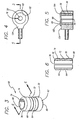
- the spool valve carries a cylindrical sleeve 60 which in turn receives the ball 50 in driving engagement.
- the means for coupling the motor to the valve is an opening directly into the center of the valve.
- the cylindrical sleeve 60 is illustrated in further detail.
- the sleeve 60 has an outer surface 62 and an inner surface 68.
- the outer surface 62 defines a pair of grooves 64 and 66 which effectively define lands 70, 72 and 74.
- the lands 70, 72 and 74 engage the inner surface of the spool valve 18.
- the grooves 64 and 66 carry an adhesive such as an epoxy resin which is utilized to secure the cylindrical sleeve 60 in place within the spool valve 18.
- the sleeve 60 is split as is shown at 76 and also defines a beveled edge 78 and 80 at the top and bottom thereof as viewed in Figs. 3 and 6.
- the split 76 along with the beveled edges 78 and 80 function to permit the sleeve 60 to be more readily and easily inserted within the spool valve 18.
- the inner diameter of the opening in the spool valve 18 is slightly less than the outer diameter of the sleeve 60, thus to be inserted, the sleeve 60 may be constricted and then inserted into the opening provided in the spool valve 18.
- the beveled edge 78 or 80 allows for easier insertion of the cylindrical sleeve 60 into the opening in the spool valve 18.
- the split 76 also accommodates the difference between the metallic spool valve 18 and the sleeve 60 insofar as the coefficient of thermal expansion and contraction is concerned.
- the cylindrical sleeve 60 is manufactured from an engineering resin which has high performance characteristics. The most critical of these characteristics is that it has a low modulus of elasticity, typically 6.89 x 10 8 - 1.38 x 10 10 Pa (1x10 5 to 2x10 6 psi), a low coefficient of friction, and high wear resistance. Lubricants (such as graphite or molybdenum disulfide) can be added to the resins to lower the coefficient of friction and increase the wear resistance of the sleeve 60.
- the plastic material from which the sleeve 60 is formed most preferably is such that it may be injection molded to provide the configuration desired for the sleeve. Usually such engineering plastics are lighter in weight and are strength competitive with metals. Also, such plastics are capable of operating at relatively high temperatures on the order of 232 - 260°C (450°F to 500°F).
- resins which may be utilized to provide the cylindrical sleeve 60 are polyphenylen sulfide polyamide-imide and polyimide.
- the presently preferred engineering molding resin is a polyamide sold by the DuPont Company, polymer products department at Willmington, Delaware under the trademark VESPEL.
- Another preferred engineering molding resin is a polyamide-imide polymer sold by Amoco Chemicals Corporation of Chicago, Illinois under the trademark TORLON.
- the low coefficient of friction of these materials provides an inherent lubricity which functions to allow an interference fit between the spherical ball 50 at the end of the motor shaft and the internal surface 68 of the sleeve 60.
- the ball and an opening in the fitting or the spool had to be lapped to provide a clearance of 0 - 1.27 x 10 -3 mm (0 to .00005 inches) for proper operation.
- such critical dimensioning and expensive manufacturing procedures may be eliminated.
- the cylindrical sleeve is inserted along with the adhesive into it's receptacle.
- the internal surface 68 is reamed to the desired size to receive the spherical ball.
- the reamed diameter of the inner surface 68 is such as to be slightly smaller than the outer diameter of the spherical ball, thus providing zero to an interference fit of 0.0127 mm (.0005 inches).
- the low modulus of elasticity allows the cylindrical sleeve area on the inner surface 68 which is in contact with the ball to conform to the outer surface of the ball without excessive contact pressure between the two parts.
- the inherent lubricity of the material in conjunction with the low contact pressure eliminates unwanted threshold characteristics which would occur with a metal to metal interference fit.
- the inherent lubricity also permits a coupling of the type disclosed herein to be utilized with other fluids which do not provide lubrication such as water or air.
- a valve 100 includes a motor 112 secured to a housing 114 by appropriate fasteners 116.
- a valve 118 controls the flow of fluid under pressure from a source 120 to output ports 122 and 124 and to return 132.
- the valve 118 include a spool 126 reciprocally disposed within a sleeve 128 which is received within a bore 130 in the housing.
- a rod 158 has one end thereof secured to one end of the spool 126 and the other end 156 thereof secured to a fitting 154 which receives a molded pastic sleeve 160.
- the sleeve 160 receives a ball 150 formed on the distal end of the rotor 36 shaft 48.
- the motor is the same as that described with respect to Figure 1 and such is designated by using the same reference numerals.
- the cylindrical sleeve 60 is inserted into the fitting 154 so that the outer surface 62 thereof is in intimate engagement with the interior surface 82 of the fitting 154.
- the grooves 64 and 66 carry an adhesive such as an epoxy resin which engages the surface 182 of the fitting 154 and when fully set secures the cylindrical sleeve 60 in place within the fitting 154.
- the sleeve 60 is compressed through the utilization of a jig or fixture so that the split 76 effectively disappears and the sleeve 60 is then inserted into the opening defined by the surface 182 of the fitting 154. The sleeve when inserted is then allowed to expand so that it is in intimate engagement with the inner surface 182 of the fitting 154.
- the cylindrical sleeve may include a radially outwardly extending flange 184 at the top thereof.
- the utilization of the flange 184 would limit the travel of the sleeve 60 downwardly.
- the cylindrical sleeve 60 is constructed of the materials as above described and is configured substantially the same as is illustrated in Fig. 3 and 6 with the exception that the upper bevel 78 is replaced by the outwardly extending flange 184.
Landscapes
- Engineering & Computer Science (AREA)
- Physics & Mathematics (AREA)
- Fluid Mechanics (AREA)
- Mechanical Engineering (AREA)
- General Engineering & Computer Science (AREA)
- Electrically Driven Valve-Operating Means (AREA)
- Multiple-Way Valves (AREA)
- Servomotors (AREA)
Description
Claims (4)
- A direct servovalve comprising:a) a housing (14;114) defining a bore (19) therein;b) a valve spool (18) disposed in said bore for reciprocation therein, said valve spool (18) defining an opening therein;c) a cylindrical sleeve (60; 160) having an inner surface (68) and an outer surface (62) disposed within said opening;d) a drive motor (12; 112) mounted on said housing (14; 114) and including a rotor (36) having a shaft (48) and an eccentrically disposed ball (50; 150) extending from said shaft (48), said ball (50; 150) being received within said sleeve (60; 160) for reciprocally driving said valve spool (18), said ball having an interference fit with said inner surface (68) of said sleeve (60; 160);
characterised in thate) said sleeve (60; 160) is formed of engineering plastic material having a low modulus of elasticity and a low coefficient of friction, andf) said outer surface of said cylindrical sleeve includes a plurality of circumferential lands (70, 72, 74) separated by circumferential grooves (64, 66), said grooves (64, 66) carrying an adhesive for securing said cylindrical sleeve (60, 160) to said valve spool. - A direct drive servovalve according to claim 1 wherein said cylindrical sleeve defines a slot (76) therethrough.
- A direct drive servovalve according to claim 2 wherein said cylindrical sleeve includes beveled outer edges (78, 80) at top and bottom surface thereof.
- A direct drive servovalve according to claim 3 in said cylindrical sleeve further includes a radially extending flange (184) at one end thereof.
Applications Claiming Priority (3)
| Application Number | Priority Date | Filing Date | Title |
|---|---|---|---|
| US09/170,134 US6000678A (en) | 1998-10-12 | 1998-10-12 | Motor/spool interface for direct drive servovalve |
| US170134 | 1998-10-12 | ||
| PCT/US1999/007674 WO2000022304A1 (en) | 1998-10-12 | 1999-04-07 | Improved motor/spool interface for direct drive servovalve |
Publications (3)
| Publication Number | Publication Date |
|---|---|
| EP1119711A1 EP1119711A1 (en) | 2001-08-01 |
| EP1119711A4 EP1119711A4 (en) | 2002-01-02 |
| EP1119711B1 true EP1119711B1 (en) | 2004-11-24 |
Family
ID=22618675
Family Applications (1)
| Application Number | Title | Priority Date | Filing Date |
|---|---|---|---|
| EP99916490A Expired - Lifetime EP1119711B1 (en) | 1998-10-12 | 1999-04-07 | Improved motor/spool interface for direct drive servovalve |
Country Status (6)
| Country | Link |
|---|---|
| US (1) | US6000678A (en) |
| EP (1) | EP1119711B1 (en) |
| JP (1) | JP2002527686A (en) |
| AU (1) | AU3480099A (en) |
| DE (1) | DE69922237T2 (en) |
| WO (1) | WO2000022304A1 (en) |
Families Citing this family (8)
| Publication number | Priority date | Publication date | Assignee | Title |
|---|---|---|---|---|
| US6334604B1 (en) * | 2000-06-13 | 2002-01-01 | Hr Textron, Inc. | Direct drive valve ball drive mechanism and method of manufacturing the same |
| US7273068B2 (en) * | 2004-01-14 | 2007-09-25 | Honeywell International, Inc. | Electric driven, integrated metering and shutoff valve for fluid flow control |
| JP5981567B2 (en) | 2012-02-09 | 2016-08-31 | ムーグ インコーポレーテッド | Electro-hydraulic servo valve |
| BR112014020497B1 (en) * | 2012-02-23 | 2021-03-09 | Moog Inc | direct drive servo valve |
| DE102013001148A1 (en) * | 2013-01-24 | 2014-07-24 | Voith Patent Gmbh | Piston valve |
| US20150117804A1 (en) * | 2013-10-30 | 2015-04-30 | United Technologies Corporation | Gas turbine engine bushing |
| EP3284956B1 (en) * | 2016-08-16 | 2019-07-24 | Hamilton Sundstrand Corporation | Servovalve |
| EP3406949B1 (en) | 2017-05-22 | 2022-11-16 | Claverham Limited | Spool valve |
Family Cites Families (16)
| Publication number | Priority date | Publication date | Assignee | Title |
|---|---|---|---|---|
| US2697016A (en) * | 1951-09-22 | 1954-12-14 | Samuel J Spurgeon | Means for securing bearing races to shafts and the like |
| US2769943A (en) * | 1953-04-20 | 1956-11-06 | Milwaukee Gas Specialty Co | Electromagnetic control device |
| US3115373A (en) * | 1961-06-19 | 1963-12-24 | Polymer Processes Inc | Permanently self-aligned bearing installation |
| US3550631A (en) * | 1968-06-17 | 1970-12-29 | Pneumo Dynamics Corp | Valve plunger drive mechanism |
| US4197474A (en) * | 1977-09-19 | 1980-04-08 | Honigsbaum Richard F | Hermetic clutch |
| US4339737A (en) * | 1980-09-22 | 1982-07-13 | Cummins Engine Company, Inc. | Rotary electrically actuated device |
| US4452423A (en) * | 1982-08-03 | 1984-06-05 | Martin Marietta Corporation | Magnetically actuated valve |
| US4573494A (en) * | 1985-01-28 | 1986-03-04 | Pneumo Corporation | Spherical ball drive mechanism for a direct drive valve |
| US4641812A (en) * | 1985-05-23 | 1987-02-10 | Pneumo Corporation | Direct drive valve and force motor assembly including interchangeable stator assembly and alignment system or method |
| US4645178A (en) * | 1985-11-22 | 1987-02-24 | Pneumo Abex Corporation | Redundant drive mechanisms for a direct drive valve and force motor assembly |
| US4793337A (en) * | 1986-11-17 | 1988-12-27 | E. R. Squibb & Sons, Inc. | Adhesive structure and products including same |
| US5040568A (en) * | 1990-07-10 | 1991-08-20 | Hr Textron Inc. | Direct drive servovalve having positive radial limit stop |
| US5052441A (en) * | 1990-09-27 | 1991-10-01 | Hr Textron Inc. | Direct drive servovalve having bearing-located motor housing |
| US5263681A (en) * | 1992-11-23 | 1993-11-23 | Hr Textron, Inc. | Motor-to-spool coupling for rotary-to-linear direct drive valve |
| US5263680A (en) * | 1992-11-23 | 1993-11-23 | Hr Textron, Inc. | Motor-to-spool coupling for rotary-to-linear direct drive valve |
| JP2824236B2 (en) * | 1996-03-26 | 1998-11-11 | 株式会社コミュータヘリコプタ先進技術研究所 | Direct drive type hydraulic servo valve |
-
1998
- 1998-10-12 US US09/170,134 patent/US6000678A/en not_active Expired - Fee Related
-
1999
- 1999-04-07 DE DE69922237T patent/DE69922237T2/en not_active Expired - Lifetime
- 1999-04-07 EP EP99916490A patent/EP1119711B1/en not_active Expired - Lifetime
- 1999-04-07 WO PCT/US1999/007674 patent/WO2000022304A1/en not_active Ceased
- 1999-04-07 AU AU34800/99A patent/AU3480099A/en not_active Abandoned
- 1999-04-07 JP JP2000576178A patent/JP2002527686A/en active Pending
Also Published As
| Publication number | Publication date |
|---|---|
| DE69922237D1 (en) | 2004-12-30 |
| EP1119711A4 (en) | 2002-01-02 |
| JP2002527686A (en) | 2002-08-27 |
| US6000678A (en) | 1999-12-14 |
| AU3480099A (en) | 2000-05-01 |
| WO2000022304A1 (en) | 2000-04-20 |
| EP1119711A1 (en) | 2001-08-01 |
| DE69922237T2 (en) | 2005-04-14 |
Similar Documents
| Publication | Publication Date | Title |
|---|---|---|
| CN104180567A (en) | Electronic expansion valve | |
| US8398934B2 (en) | Coupling system for use with fluid displacement apparatus | |
| US6172847B1 (en) | Rotational assembly for disc drive device having small runout and reduced axial displacement | |
| US6000678A (en) | Motor/spool interface for direct drive servovalve | |
| AU727704B2 (en) | Reciprocating piston compressor | |
| US5947003A (en) | Hydraulic piston machine with friction-reducing layer on the cylinder and the cylinder bearing | |
| US5469776A (en) | Hydraulic pumping device | |
| US5263680A (en) | Motor-to-spool coupling for rotary-to-linear direct drive valve | |
| US7690293B2 (en) | Coupling system for use with fluid displacement apparatus | |
| US5263681A (en) | Motor-to-spool coupling for rotary-to-linear direct drive valve | |
| US4673337A (en) | Hydraulic radial piston pump intake porting arrangement | |
| EP2410180B1 (en) | Rocking piston type compressor | |
| AU2002219963B2 (en) | High pressure low volume pump | |
| US20240149852A1 (en) | Brake device for vehicle | |
| KR100278518B1 (en) | Magnetic screw device | |
| US6113304A (en) | Coupling for high pressure fluid pump assembly | |
| US4970484A (en) | Composite elastomer-tipped tubular metallic device for armature and needle valve applications | |
| US10851842B2 (en) | Power transmission device | |
| US12169022B2 (en) | Piston compressor | |
| US6874533B2 (en) | 3/2 Normally closed module | |
| US5059039A (en) | Magnetic bearing bushing | |
| CN213655731U (en) | Sealing device and vacuum equipment with same | |
| CN102575770B (en) | Seal device | |
| US5053655A (en) | Motor-compressor unit | |
| JPH08232910A (en) | Compound actuator |
Legal Events
| Date | Code | Title | Description |
|---|---|---|---|
| PUAI | Public reference made under article 153(3) epc to a published international application that has entered the european phase |
Free format text: ORIGINAL CODE: 0009012 |
|
| 17P | Request for examination filed |
Effective date: 20010327 |
|
| AK | Designated contracting states |
Kind code of ref document: A1 Designated state(s): DE FR GB IT |
|
| A4 | Supplementary search report drawn up and despatched |
Effective date: 20011115 |
|
| AK | Designated contracting states |
Kind code of ref document: A4 Designated state(s): DE FR GB IT |
|
| 17Q | First examination report despatched |
Effective date: 20030204 |
|
| GRAP | Despatch of communication of intention to grant a patent |
Free format text: ORIGINAL CODE: EPIDOSNIGR1 |
|
| GRAS | Grant fee paid |
Free format text: ORIGINAL CODE: EPIDOSNIGR3 |
|
| GRAA | (expected) grant |
Free format text: ORIGINAL CODE: 0009210 |
|
| AK | Designated contracting states |
Kind code of ref document: B1 Designated state(s): DE FR GB IT |
|
| REG | Reference to a national code |
Ref country code: GB Ref legal event code: FG4D |
|
| REF | Corresponds to: |
Ref document number: 69922237 Country of ref document: DE Date of ref document: 20041230 Kind code of ref document: P |
|
| ET | Fr: translation filed | ||
| PLBE | No opposition filed within time limit |
Free format text: ORIGINAL CODE: 0009261 |
|
| STAA | Information on the status of an ep patent application or granted ep patent |
Free format text: STATUS: NO OPPOSITION FILED WITHIN TIME LIMIT |
|
| 26N | No opposition filed |
Effective date: 20050825 |
|
| PGFP | Annual fee paid to national office [announced via postgrant information from national office to epo] |
Ref country code: FR Payment date: 20100506 Year of fee payment: 12 |
|
| PGFP | Annual fee paid to national office [announced via postgrant information from national office to epo] |
Ref country code: IT Payment date: 20100427 Year of fee payment: 12 Ref country code: DE Payment date: 20100428 Year of fee payment: 12 |
|
| PGFP | Annual fee paid to national office [announced via postgrant information from national office to epo] |
Ref country code: GB Payment date: 20100426 Year of fee payment: 12 |
|
| REG | Reference to a national code |
Ref country code: DE Ref legal event code: R119 Ref document number: 69922237 Country of ref document: DE |
|
| REG | Reference to a national code |
Ref country code: DE Ref legal event code: R119 Ref document number: 69922237 Country of ref document: DE |
|
| GBPC | Gb: european patent ceased through non-payment of renewal fee |
Effective date: 20110407 |
|
| REG | Reference to a national code |
Ref country code: FR Ref legal event code: ST Effective date: 20111230 |
|
| PG25 | Lapsed in a contracting state [announced via postgrant information from national office to epo] |
Ref country code: FR Free format text: LAPSE BECAUSE OF NON-PAYMENT OF DUE FEES Effective date: 20110502 |
|
| PG25 | Lapsed in a contracting state [announced via postgrant information from national office to epo] |
Ref country code: IT Free format text: LAPSE BECAUSE OF NON-PAYMENT OF DUE FEES Effective date: 20110407 Ref country code: GB Free format text: LAPSE BECAUSE OF NON-PAYMENT OF DUE FEES Effective date: 20110407 |
|
| PG25 | Lapsed in a contracting state [announced via postgrant information from national office to epo] |
Ref country code: DE Free format text: LAPSE BECAUSE OF NON-PAYMENT OF DUE FEES Effective date: 20111031 |