EP1119465B1 - Vehicle air conditioning - Google Patents
Vehicle air conditioning Download PDFInfo
- Publication number
- EP1119465B1 EP1119465B1 EP99947730A EP99947730A EP1119465B1 EP 1119465 B1 EP1119465 B1 EP 1119465B1 EP 99947730 A EP99947730 A EP 99947730A EP 99947730 A EP99947730 A EP 99947730A EP 1119465 B1 EP1119465 B1 EP 1119465B1
- Authority
- EP
- European Patent Office
- Prior art keywords
- air
- cooling unit
- heating means
- vehicle
- evaporator
- Prior art date
- Legal status (The legal status is an assumption and is not a legal conclusion. Google has not performed a legal analysis and makes no representation as to the accuracy of the status listed.)
- Expired - Lifetime
Links
Images



Classifications
-
- B—PERFORMING OPERATIONS; TRANSPORTING
- B60—VEHICLES IN GENERAL
- B60H—ARRANGEMENTS OF HEATING, COOLING, VENTILATING OR OTHER AIR-TREATING DEVICES SPECIALLY ADAPTED FOR PASSENGER OR GOODS SPACES OF VEHICLES
- B60H1/00—Heating, cooling or ventilating devices
- B60H1/32—Cooling devices
- B60H1/3204—Cooling devices using compression
- B60H1/3205—Control means therefor
- B60H1/321—Control means therefor for preventing the freezing of a heat exchanger
-
- B—PERFORMING OPERATIONS; TRANSPORTING
- B60—VEHICLES IN GENERAL
- B60H—ARRANGEMENTS OF HEATING, COOLING, VENTILATING OR OTHER AIR-TREATING DEVICES SPECIALLY ADAPTED FOR PASSENGER OR GOODS SPACES OF VEHICLES
- B60H1/00—Heating, cooling or ventilating devices
- B60H1/00007—Combined heating, ventilating, or cooling devices
- B60H1/00021—Air flow details of HVAC devices
- B60H1/00035—Air flow details of HVAC devices for sending an air stream of uniform temperature into the passenger compartment
-
- B—PERFORMING OPERATIONS; TRANSPORTING
- B60—VEHICLES IN GENERAL
- B60H—ARRANGEMENTS OF HEATING, COOLING, VENTILATING OR OTHER AIR-TREATING DEVICES SPECIALLY ADAPTED FOR PASSENGER OR GOODS SPACES OF VEHICLES
- B60H1/00—Heating, cooling or ventilating devices
- B60H1/00007—Combined heating, ventilating, or cooling devices
- B60H1/00021—Air flow details of HVAC devices
- B60H2001/00114—Heating or cooling details
- B60H2001/00142—Heating or cooling details first heating and then cooling
Definitions
- the present invention relates to vehicle air conditioning.
- Vehicle air conditioning systems which comprise evaporators positioned to cool airflow upstream of heater units, which heater units are operable to add heat to the air downstream of the evaporator when required.
- the evaporator also acts as a de-humidifier for the air. Air is drawn in from the exterior of the vehicle, or recirculated from the vehicle cabin and directed through one or both of the evaporator and heater dependent upon the ambient conditions (such as the humidity or temperature of the air passing through the system) and the system requirements set by the passenger.
- the temperature difference between the refrigerant fluid in the evaporator and the air passing -through the evaporator provides the driving mechanism which causes heat transfer to occur.
- ambient temperatures are low (such as in cold climates) achieving an enthalpy change sufficient for adequate evaporation of the refrigerant in the evaporator becomes a problem.
- a level is reached at which ambient air temperature is so low that complete evaporation is not possible.
- the system becomes increasingly inoperable because, amongst other things, incompressible (un-evaporated) refrigerant can enter the compressor driving the system.
- DE-A-19651279 shows the preamble of claim 1.
- a vehicle air conditioning system comprising:
- the invention operates by utilising the upstream heating means to load the air temperature before the air reaches the air cooling unit so as to consequently increase the heat flux across the air cooling unit.
- the external operational temperature window for the air conditioning cycle is consequently widened because the system is able to tolerate a lower ambient external air temperature range.
- the humidity control of the conditioned air may be improved.
- the air cooling unit comprises part of a refrigerant fluid circuit, the air cooling unit preferably comprising an evaporator.
- the condenser comprising the second air heating means beneficially comprises part of a refrigerant fluid circuit.
- a refrigerant fluid circuit comprising the air conditioning system desirably includes:
- the refrigerant fluid circuit preferably comprises sub circuits each having a common portion passing through the evaporator and discrete portions each having a respective condenser.
- the bypass means is preferably adjustable permitting varying proportions of air to pass through and bypass the heating means according to system requirements. Additionally, the output of the heater means may be manipulated to vary or prevent the heating effect on the airflow.
- the air heating means upstream of the air cooling unit may comprise a heater supplied with heat from the engine cooling circuit of the vehicle, or, alternatively, an electrical heating device.
- Other heating arrangements are also envisaged making use of other heat sources of the vehicle, for example fuel burners or waste heat from other sources.
- the invention provides a method of controlling a vehicle air conditioning system comprising:
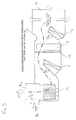
- an air conditioning system 101 comprising a refrigerant circuit including a compressor 1, primary condenser 4, thermal expansion valve 7a and evaporator 13.
- Compressor 1 compresses the refrigerant vapour to a high pressure and temperature.
- a directional valve 2 has an inlet from the compressor and can be configured to direct flow toward the primary condenser 4.
- the condenser 4 is located at the front of the vehicle bay, behind the air inlet grill of the vehicle (not shown). Air is passed through the primary condenser 4 aided by a fan 5.
- Receiver-dryer 6a acts as a reservoir for refrigerant that accommodates variation in demand from the refrigeration circuit. It also separates condensed liquid refrigerant from vapour refrigerant to ensure that only liquid phase refrigerant passes to the expansion valve 7a.
- Receiver-dryer 6a commonly contains a desiccant designed to remove any moisture from the circulating refrigerant (and also commonly contains filter material to entrap any particulate impurities).
- Thermal expansion valve 7a performs irreversible, adiabatic expansion of the condensed liquid into low pressure liquid ready for evaporation in the evaporator 13.
- the throttling function of expansion valve 7a is controlled through feedback of temperature and pressure for vapour exiting the evaporator 13.
- the evaporator 13 is positioned in ducting 16 at one end of which is an air inlet 8 (which may be either a "fresh-air" intake 8a from externally of the vehicle, or a circulating air intake 8b from inside the vehicle - or a proportion from each according to the position of diverter 9c).
- the ducking 16 expends to in-cabin distribution vents 15 distributing the conditioned air into the vehicle cabin.
- a blower and motor 10 draws air into the distribution ducting 16.
- air flow diverters 9a, 9b direct the air flow to follow one of several potential selected paths.
- upstream of the evaporator 13 is provided a heater 11. This heater facilitates heat transfer to the air crossing across it such that the air is heated from passage through this component.
- an optional filter 12 Downstream of heater 11 and immediately upstream of evaporator 13 is positioned an optional filter 12 used to filter particulate matter and also vehicle pollutant (eg NOx) from the air being passed into the vehicle cabin environment.
- vehicle pollutant eg NOx
- a secondary condenser 14 Downstream of evaporator 13 is positioned a secondary condenser 14 to provide a heat source that can be used to heat air, having passed through evaporator 13, prior to distribution into the interior of the vehicle cabin.
- Valve 2 is switchable to cause refrigerant flow (under the influence of compressor 1) through the secondary condenser 14 rather than the primary condenser 4.
- the refrigeration circuit thereby effectively comprises two sub-circuits having a common portion (including a common evaporator) and separate, alternative switchable portions including separate condensers. The nature and purpose of the switching between sub-circuit portions is described in detail below.
- Respective diverters 9a and 9b are positioned immediately upstream of respective heater 11 and secondary condenser 14 and switchable (by the air conditioning control) between positions in which air is permitted to pass through the relevant heater 11 or secondary condenser 14, or substantially inhibited from doing so.
- the heater 11, evaporator 13 , secondary condenser 14 and airflow diverters 9a,9b comprise the main air conditioning and distribution components for the vehicle air conditioning system.
- control of the system may be used to produce various air conditioning effects depending on the desired, and ambient, conditions.
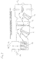
- FIG. 2 The arrangement shown in Figure 2 is generally similar to the arrangement shown in Figure 1, however the receiver dryer 6a and expansion valve 7a are replaced with an accumulator 6b and orifice tube 7b.
- Accumulator 6b acts as a reservoir for unevaporated refrigerant, and also separates unevaporated refrigerant from vapour to ensure that only vapour passes to the compressor 1.
- Accumulator 6b removes moisture from the circulating refrigerant and can trap particulate impurities.
- Orifice tube 7b similarly to expansion valve 7a, performs irreversible adiabatic expansion of condensed liquid into low pressure liquid ready for evaporation in evaporator 13.
- the orifice can be varied to increase system flexibility in response to refrigeration demand fluctuation.
- the operation of the air conditioning system according to the invention can be varied by the air conditioning control according to external and/or desired internal conditions.
- the principle requirement is to heat the in-cabin environment.
- the air-intake 8 is controlled such that diverter 9c closes external air intake 8a such that external air is prevented from accessing the in-cabin system.
- the airflow is directed, utilising air flow diverter 9a, across the heater 11. This raises air temperature (dependent upon the heat energy available from heater 11) to the desired level.
- Evaporator 13 temperature sensing delays operation of the refrigerant circuit until a predetermined minimum temperature air-on criterion is reached.
- the refrigerant vapour Upon entering the secondary condenser 14, the refrigerant vapour is encouraged to condense via heat exchange with the airflow across unit 14, thereby releasing the latent heat of condensation to the air-stream and raising its temperature.
- refrigerant liquid (and any residual vapour) travel to the receiver drier unit 6a, via the unidirectional valve 3b.
- Valve 3c avoids flow into the redundant circuit to unit 4.
- the refrigerant liquid is filtered, desiccated, stored and separated from any vapour fraction. This action ensures only high pressure liquid is drawn from receiver-dryer 6a to enter the expansion valve 7a.
- Expansion valve 7a facilitates irreversible, adiabatic expansion of condensed liquid into low pressure liquid ready for evaporation in evaporator 13.
- the throttling function of this valve is controlled through temperature and pressure feedback measurement from the vapour condition exiting the evaporator 13.
- the refrigerant liquid Upon entry into the evaporator, the refrigerant liquid is encouraged to evaporate via heat exchange with the airflow across unit 13, thereby drawing the latent heat for vaporisation from the air stream and lowering the air stream temperature (the air temperature having been previously raised via passage through heater unit 11).
- refrigerant vapour travels back to the compressor component 1.
- recirculated air is heated by component 11, passes across optional filter 12 and enters the evaporator 13. Heat exchange takes place across 13, resulting in the consequent lowering of the air temperature. This encourages dehumidification because the vapour solubility for moisture is reduced with reducing temperature and moisture from the air stream is encouraged to condense upon the colder surface evaporator 13. Cooled air with reduced humidity exits from evaporator 13 and is directed, via the action of diverter 9b, onto the secondary condenser 14. The enthalpy drawn from the air during passage across the evaporator 13 (latent heat of vaporisation), is now relinquished to the air via the condensing action of the refrigerant within secondary condenser 14. The reduced humidity air is then directed to the mixing and distribution section. 15, and subsequently into the car interior airspace via ducts and vents.
- the recirculation mode is controlled against the temperature levels within the heater 11. When sufficient temperatures are reached in this heater 11 to heat an influx of ambient, external air above the minimum evaporator air on temperature criterion, then such fresh air is introduced to avoid potential, excessive dehumidification of the in-cabin environment, and subsequent vehicle occupant discomfort.
- the air passes across filter 12 and passes through evaporator 13. No heat exchange would take place during passage through evaporator 13, because the refrigeration circuit is non-operational.
- Compressor 1 engages, and high pressure/temperature refrigerant vapour is directed by valve 2 toward the primary condenser 4.
- the refrigerant vapour Upon entering the primary condenser 4, the refrigerant vapour is encouraged to condense via heat exchange with the underbonnet airflow across unit 4, thereby releasing the latent heat of condensation to the underbonnet air stream and raising its temperature.
- refrigerant liquid and any residual vapour travel to the receiver drier unit 6a, via the unidirectional valve 3c.
- the refrigerant liquid is filtered, desiccated, stored and separated from any vapour fraction. This action ensures only high pressure liquid is drawn from component 6a to enter the expansion valve component 7a.
- This expansion valve facilitates irreversible, adiabatic expansion of condensed liquid into low pressure liquid ready for evaporation in evaporator 13.
- the throttling function of this valve is controlled through temperature and pressure feedback measurement from the vapour condition exiting the evaporator 13.
- the refrigerant liquid Upon entry into the evaporator, the refrigerant liquid is encouraged to evaporate (within the evaporator unit) via heat exchange with the airflow across unit 13 (outside the evaporator unit), thereby drawing the latent heat for vaporisation from the air stream and lowering its temperature (the air temperature having been previously conditioned via air passage through and/or around heater unit 11).
- refrigerant vapour Upon exit from evaporator 13, refrigerant vapour travels back to the compressor 1.
- the relative mixing of the fresh air, heated air and evaporator duty beneficially requires algorithmic control to achieve the optimum temperature balance.
- Conditioned air with reduced humidity exits from evaporator 13 and is directed, via the action of diverter 9b, to by-pass the non-operational, secondary condenser 14. The air is then directed to the mixing and distribution section 15, and subsequently into the car interior airspace via ducts and vents.
- the evaporator duty might require algorithmic control to achieve the correct temperature balance.
Landscapes
- Physics & Mathematics (AREA)
- Thermal Sciences (AREA)
- Engineering & Computer Science (AREA)
- Mechanical Engineering (AREA)
- Air-Conditioning For Vehicles (AREA)
- Sorption Type Refrigeration Machines (AREA)
Abstract
Description
- a) monitoring system demand and/or ambient conditions interior and/or exterior of the vehicle; and,
- b) modifying the passage of air in response to the monitoring of step a) to change the proportion of air by passing the air heating means or second air heating means to vary between 0-100 percent; and/or,
- c) modifying the heat output of the heating means; and/or,
- d) modifying the cooling effect of the cooling unit.
Claims (8)
- A vehicle air conditioning system (101) comprising:characterized by the second air heating means comprising a condenser (14); and where first heater bypass means (9a) is provided enabling at least some of the air flow to bypass the first air heating means and/or second heater bypass means (9b) is provided enabling at least some of the air flow to bypass the second air heating means.i) an air cooling unit (13);ii) air heating means (11) positioned upstream of the air cooling unit (13); andiii) second air heating means (14) downstream of the air cooling unit,
- A vehicle air conditioning system according to claim 1, wherein:i) the air cooling unit (13) comprises part of a refrigerant fluid circuit; and/or,ii) wherein the air cooling unit (13) comprises an evaporator.
- A vehicle air conditioning system according to any preceding claim, wherein the condenser (14) comprising the second air heating means comprises part of a refrigerant fluid circuit.
- A vehicle air conditioning system according to claim 3, wherein the refrigerant fluid circuit comprising the air conditioning system includes:i) an evaporator (13) comprising the air cooling unit;ii) a condenser (14) arranged downstream of the air cooling unit;iii) a condenser (4) remote from the flow of conditioned air;iv) switching means (2) for switching the flow of refrigerant to pass through the evaporator and preferentially one or other of the condensers.
- A vehicle air conditioning system according to claim 4, wherein the refrigerant fluid circuit comprises sub circuits each having a common portion passing through the evaporator and discrete portions each having a respective condenser.
- A vehicle air conditioning system according to any preceding claim, wherein heater output may be varied to alter or prevent the heating effect on the airflow.
- A vehicle air conditioning system according to any preceding claim, wherein:i) the air heating means (11) upstream of the air cooling unit comprises a heater supplied with heat from the engine cooling circuit of the vehicle; orii) the air heating means (11) upstream of the air cooling unit comprises an electrical heating device.
- A method of controlling a vehicle air conditioning system (101) comprising:the method comprising:i) an air cooling unit (13);ii) air heating means (11) positioned upstream of the air cooling unit (13); andiii) second air heating means downstream of the air cooling unit, the second air heating means comprising a condenser (14)a) monitoring system demand and/or ambient conditions interior and/or exterior of the vehicle; and,b) modifying the passage of air in response to the monitoring of step a) to change the proportion of air by passing the air heating means or second air heating means to vary between 0-100 percent; and/or,c) modifying the heat output of the heating means; and/or,d) modifying the cooling effect of the cooling unit.
Applications Claiming Priority (3)
| Application Number | Priority Date | Filing Date | Title |
|---|---|---|---|
| GB9821743A GB2342436B (en) | 1998-10-07 | 1998-10-07 | Vehicle air conditioning |
| GB9821743 | 1998-10-07 | ||
| PCT/GB1999/003266 WO2000020240A1 (en) | 1998-10-07 | 1999-10-04 | Vehicle air conditioning |
Publications (2)
| Publication Number | Publication Date |
|---|---|
| EP1119465A1 EP1119465A1 (en) | 2001-08-01 |
| EP1119465B1 true EP1119465B1 (en) | 2004-04-21 |
Family
ID=10840072
Family Applications (1)
| Application Number | Title | Priority Date | Filing Date |
|---|---|---|---|
| EP99947730A Expired - Lifetime EP1119465B1 (en) | 1998-10-07 | 1999-10-04 | Vehicle air conditioning |
Country Status (6)
| Country | Link |
|---|---|
| EP (1) | EP1119465B1 (en) |
| AT (1) | ATE264763T1 (en) |
| AU (1) | AU6110499A (en) |
| DE (1) | DE69916637T2 (en) |
| GB (1) | GB2342436B (en) |
| WO (1) | WO2000020240A1 (en) |
Families Citing this family (4)
| Publication number | Priority date | Publication date | Assignee | Title |
|---|---|---|---|---|
| US5742543A (en) | 1996-08-19 | 1998-04-21 | Intel Corporation | Flash memory device having a page mode of operation |
| US6715307B2 (en) * | 2001-01-24 | 2004-04-06 | Calsonic Kansei Corporation | Air conditioner for vehicle |
| DE10336248B3 (en) * | 2003-08-07 | 2004-09-30 | J. Eberspächer GmbH & Co. KG | Temperature control system for a motor vehicle comprises an evaporator, a first heat-exchanger arrangement downstream of the evaporator, and a heating arrangement with a second heat exchanger arrangement upstream of the evaporator |
| DE10346827B4 (en) * | 2003-10-06 | 2017-07-13 | Mahle International Gmbh | Method for regulating the air temperature of a motor vehicle air conditioning system with auxiliary heating function |
Family Cites Families (8)
| Publication number | Priority date | Publication date | Assignee | Title |
|---|---|---|---|---|
| GB902040A (en) * | 1959-09-23 | 1962-07-25 | Carrier Engineering Co Ltd | Improvements in or relating to air treating apparatus |
| CA948123A (en) * | 1968-11-26 | 1974-05-28 | John W. Benedict | Air purification system |
| DE2635860A1 (en) * | 1976-08-10 | 1978-02-23 | Draegerwerk Ag | VENTILATION DEVICE FOR PASSENGER VEHICLES, IN PARTICULAR COMBAT VEHICLES, SANITARY VEHICLES, COMMAND VEHICLES, etc. |
| US4733605A (en) * | 1983-10-11 | 1988-03-29 | Heinz Holter | Process and device for purifying polluted air |
| JPH0241917A (en) * | 1988-08-01 | 1990-02-13 | Nippon Denso Co Ltd | Heat pump type air conditioning device for vehicle |
| FR2706816A1 (en) * | 1993-06-23 | 1994-12-30 | Valeo Thermique Habitacle | Apparatus for heating-ventilating and/or air-conditioning the passenger compartment of a motor vehicle, especially an electric vehicle |
| KR960013745U (en) * | 1994-10-12 | 1996-05-17 | Car air conditioner | |
| DE19651279B4 (en) * | 1995-12-13 | 2004-09-16 | Denso Corp., Kariya | Air conditioning for a vehicle |
-
1998
- 1998-10-07 GB GB9821743A patent/GB2342436B/en not_active Expired - Fee Related
-
1999
- 1999-10-04 EP EP99947730A patent/EP1119465B1/en not_active Expired - Lifetime
- 1999-10-04 DE DE69916637T patent/DE69916637T2/en not_active Expired - Fee Related
- 1999-10-04 AT AT99947730T patent/ATE264763T1/en not_active IP Right Cessation
- 1999-10-04 AU AU61104/99A patent/AU6110499A/en not_active Abandoned
- 1999-10-04 WO PCT/GB1999/003266 patent/WO2000020240A1/en not_active Ceased
Also Published As
| Publication number | Publication date |
|---|---|
| DE69916637D1 (en) | 2004-05-27 |
| WO2000020240A1 (en) | 2000-04-13 |
| GB9821743D0 (en) | 1998-12-02 |
| AU6110499A (en) | 2000-04-26 |
| ATE264763T1 (en) | 2004-05-15 |
| EP1119465A1 (en) | 2001-08-01 |
| DE69916637T2 (en) | 2005-01-05 |
| GB2342436B (en) | 2003-02-12 |
| GB2342436A (en) | 2000-04-12 |
Similar Documents
| Publication | Publication Date | Title |
|---|---|---|
| JP3781147B2 (en) | Heat pump type automotive air conditioner | |
| US5975191A (en) | Vehicle air conditioner | |
| US5309731A (en) | Air conditioning apparatus | |
| US11179998B2 (en) | Method of heating and cooling at least one zone of a passenger compartment of a vehicle | |
| US20190061471A1 (en) | Air-conditioning system of a motor vehicle and method for operating the air-conditioning system | |
| US5065586A (en) | Air conditioner with dehumidifying mode | |
| US5560217A (en) | Air conditioning system of heat pump type | |
| JP3939445B2 (en) | Air conditioner for automobile | |
| JP3246250B2 (en) | Heat pump air conditioner dehumidifier for electric vehicles | |
| JP3233771B2 (en) | Vehicle air conditioner | |
| US6371202B1 (en) | Vehicle air conditioner | |
| US20200254846A1 (en) | Air-Conditioning Device | |
| US20190070929A1 (en) | Air-conditioning device | |
| EP1119465A1 (en) | Vehicle air conditioning | |
| JP2019184107A (en) | Battery cooling device | |
| US5634349A (en) | Air conditioner | |
| CN111819096B (en) | Air conditioner | |
| EP1372995B1 (en) | Vehicle thermal management systems | |
| JP3369851B2 (en) | Heat pump type air conditioner for automobiles | |
| CN111163957A (en) | Air conditioner | |
| WO2023002993A1 (en) | Vehicular air conditioner | |
| KR102171163B1 (en) | Climate control system for conditioning the air of a passenger compartment of a vehicle and method for operating the climate control system | |
| KR101146477B1 (en) | Heat Pump System for Car | |
| JPH0235221B2 (en) | ||
| JP4452111B2 (en) | Air conditioner for vehicles |
Legal Events
| Date | Code | Title | Description |
|---|---|---|---|
| PUAI | Public reference made under article 153(3) epc to a published international application that has entered the european phase |
Free format text: ORIGINAL CODE: 0009012 |
|
| 17P | Request for examination filed |
Effective date: 20010423 |
|
| AK | Designated contracting states |
Kind code of ref document: A1 Designated state(s): AT BE CH CY DE DK ES FI FR GB GR IE IT LI LU MC NL PT SE |
|
| AX | Request for extension of the european patent |
Free format text: AL;LT;LV;MK;RO;SI |
|
| 17Q | First examination report despatched |
Effective date: 20011001 |
|
| GRAH | Despatch of communication of intention to grant a patent |
Free format text: ORIGINAL CODE: EPIDOS IGRA |
|
| GRAL | Information related to payment of fee for publishing/printing deleted |
Free format text: ORIGINAL CODE: EPIDOSDIGR3 |
|
| GRAS | Grant fee paid |
Free format text: ORIGINAL CODE: EPIDOSNIGR3 |
|
| GRAS | Grant fee paid |
Free format text: ORIGINAL CODE: EPIDOSNIGR3 |
|
| RAP1 | Party data changed (applicant data changed or rights of an application transferred) |
Owner name: CALSONIC KANSEI UK LIMITED |
|
| GRAA | (expected) grant |
Free format text: ORIGINAL CODE: 0009210 |
|
| AK | Designated contracting states |
Kind code of ref document: B1 Designated state(s): AT BE CH CY DE DK ES FI FR GB GR IE IT LI LU MC NL PT SE |
|
| PG25 | Lapsed in a contracting state [announced via postgrant information from national office to epo] |
Ref country code: NL Free format text: LAPSE BECAUSE OF FAILURE TO SUBMIT A TRANSLATION OF THE DESCRIPTION OR TO PAY THE FEE WITHIN THE PRESCRIBED TIME-LIMIT Effective date: 20040421 Ref country code: LI Free format text: LAPSE BECAUSE OF FAILURE TO SUBMIT A TRANSLATION OF THE DESCRIPTION OR TO PAY THE FEE WITHIN THE PRESCRIBED TIME-LIMIT Effective date: 20040421 Ref country code: IT Free format text: LAPSE BECAUSE OF FAILURE TO SUBMIT A TRANSLATION OF THE DESCRIPTION OR TO PAY THE FEE WITHIN THE PRESCRIBED TIME-LIMIT;WARNING: LAPSES OF ITALIAN PATENTS WITH EFFECTIVE DATE BEFORE 2007 MAY HAVE OCCURRED AT ANY TIME BEFORE 2007. THE CORRECT EFFECTIVE DATE MAY BE DIFFERENT FROM THE ONE RECORDED. Effective date: 20040421 Ref country code: FI Free format text: LAPSE BECAUSE OF FAILURE TO SUBMIT A TRANSLATION OF THE DESCRIPTION OR TO PAY THE FEE WITHIN THE PRESCRIBED TIME-LIMIT Effective date: 20040421 Ref country code: CY Free format text: LAPSE BECAUSE OF FAILURE TO SUBMIT A TRANSLATION OF THE DESCRIPTION OR TO PAY THE FEE WITHIN THE PRESCRIBED TIME-LIMIT Effective date: 20040421 Ref country code: CH Free format text: LAPSE BECAUSE OF FAILURE TO SUBMIT A TRANSLATION OF THE DESCRIPTION OR TO PAY THE FEE WITHIN THE PRESCRIBED TIME-LIMIT Effective date: 20040421 Ref country code: BE Free format text: LAPSE BECAUSE OF FAILURE TO SUBMIT A TRANSLATION OF THE DESCRIPTION OR TO PAY THE FEE WITHIN THE PRESCRIBED TIME-LIMIT Effective date: 20040421 Ref country code: AT Free format text: LAPSE BECAUSE OF FAILURE TO SUBMIT A TRANSLATION OF THE DESCRIPTION OR TO PAY THE FEE WITHIN THE PRESCRIBED TIME-LIMIT Effective date: 20040421 |
|
| REG | Reference to a national code |
Ref country code: GB Ref legal event code: FG4D |
|
| REG | Reference to a national code |
Ref country code: CH Ref legal event code: EP |
|
| REG | Reference to a national code |
Ref country code: IE Ref legal event code: FG4D |
|
| REF | Corresponds to: |
Ref document number: 69916637 Country of ref document: DE Date of ref document: 20040527 Kind code of ref document: P |
|
| PG25 | Lapsed in a contracting state [announced via postgrant information from national office to epo] |
Ref country code: SE Free format text: LAPSE BECAUSE OF FAILURE TO SUBMIT A TRANSLATION OF THE DESCRIPTION OR TO PAY THE FEE WITHIN THE PRESCRIBED TIME-LIMIT Effective date: 20040721 Ref country code: GR Free format text: LAPSE BECAUSE OF FAILURE TO SUBMIT A TRANSLATION OF THE DESCRIPTION OR TO PAY THE FEE WITHIN THE PRESCRIBED TIME-LIMIT Effective date: 20040721 Ref country code: DK Free format text: LAPSE BECAUSE OF FAILURE TO SUBMIT A TRANSLATION OF THE DESCRIPTION OR TO PAY THE FEE WITHIN THE PRESCRIBED TIME-LIMIT Effective date: 20040721 |
|
| PG25 | Lapsed in a contracting state [announced via postgrant information from national office to epo] |
Ref country code: ES Free format text: LAPSE BECAUSE OF FAILURE TO SUBMIT A TRANSLATION OF THE DESCRIPTION OR TO PAY THE FEE WITHIN THE PRESCRIBED TIME-LIMIT Effective date: 20040801 |
|
| LTIE | Lt: invalidation of european patent or patent extension |
Effective date: 20040421 |
|
| NLV1 | Nl: lapsed or annulled due to failure to fulfill the requirements of art. 29p and 29m of the patents act | ||
| PG25 | Lapsed in a contracting state [announced via postgrant information from national office to epo] |
Ref country code: LU Free format text: LAPSE BECAUSE OF NON-PAYMENT OF DUE FEES Effective date: 20041004 Ref country code: IE Free format text: LAPSE BECAUSE OF NON-PAYMENT OF DUE FEES Effective date: 20041004 |
|
| REG | Reference to a national code |
Ref country code: CH Ref legal event code: PL |
|
| PG25 | Lapsed in a contracting state [announced via postgrant information from national office to epo] |
Ref country code: MC Free format text: LAPSE BECAUSE OF NON-PAYMENT OF DUE FEES Effective date: 20041031 |
|
| ET | Fr: translation filed | ||
| PLBE | No opposition filed within time limit |
Free format text: ORIGINAL CODE: 0009261 |
|
| STAA | Information on the status of an ep patent application or granted ep patent |
Free format text: STATUS: NO OPPOSITION FILED WITHIN TIME LIMIT |
|
| 26N | No opposition filed |
Effective date: 20050124 |
|
| PG25 | Lapsed in a contracting state [announced via postgrant information from national office to epo] |
Ref country code: DE Free format text: LAPSE BECAUSE OF NON-PAYMENT OF DUE FEES Effective date: 20050503 |
|
| REG | Reference to a national code |
Ref country code: IE Ref legal event code: MM4A |
|
| PG25 | Lapsed in a contracting state [announced via postgrant information from national office to epo] |
Ref country code: FR Free format text: LAPSE BECAUSE OF NON-PAYMENT OF DUE FEES Effective date: 20050630 |
|
| REG | Reference to a national code |
Ref country code: FR Ref legal event code: ST |
|
| PG25 | Lapsed in a contracting state [announced via postgrant information from national office to epo] |
Ref country code: PT Free format text: LAPSE BECAUSE OF NON-PAYMENT OF DUE FEES Effective date: 20040921 |
|
| PGFP | Annual fee paid to national office [announced via postgrant information from national office to epo] |
Ref country code: GB Payment date: 20180927 Year of fee payment: 20 |
|
| REG | Reference to a national code |
Ref country code: GB Ref legal event code: PE20 Expiry date: 20191003 |
|
| PG25 | Lapsed in a contracting state [announced via postgrant information from national office to epo] |
Ref country code: GB Free format text: LAPSE BECAUSE OF EXPIRATION OF PROTECTION Effective date: 20191003 |