EP1119460B1 - A vehicle tyre having a profiled tread - Google Patents
A vehicle tyre having a profiled treadInfo
- Publication number
- EP1119460B1 EP1119460B1 EP00954540A EP00954540A EP1119460B1 EP 1119460 B1 EP1119460 B1 EP 1119460B1 EP 00954540 A EP00954540 A EP 00954540A EP 00954540 A EP00954540 A EP 00954540A EP 1119460 B1 EP1119460 B1 EP 1119460B1
- Authority
- EP
- European Patent Office
- Prior art keywords
- tread
- accordance
- tyre
- vehicle tyre
- tread block
- Prior art date
- Legal status (The legal status is an assumption and is not a legal conclusion. Google has not performed a legal analysis and makes no representation as to the accuracy of the status listed.)
- Expired - Lifetime
Links
Images


Classifications
-
- B—PERFORMING OPERATIONS; TRANSPORTING
- B60—VEHICLES IN GENERAL
- B60C—VEHICLE TYRES; TYRE INFLATION; TYRE CHANGING; CONNECTING VALVES TO INFLATABLE ELASTIC BODIES IN GENERAL; DEVICES OR ARRANGEMENTS RELATED TO TYRES
- B60C11/00—Tyre tread bands; Tread patterns; Anti-skid inserts
- B60C11/03—Tread patterns
- B60C11/13—Tread patterns characterised by the groove cross-section, e.g. for buttressing or preventing stone-trapping
- B60C11/1376—Three dimensional block surfaces departing from the enveloping tread contour
- B60C11/1384—Three dimensional block surfaces departing from the enveloping tread contour with chamfered block corners
-
- B—PERFORMING OPERATIONS; TRANSPORTING
- B60—VEHICLES IN GENERAL
- B60C—VEHICLE TYRES; TYRE INFLATION; TYRE CHANGING; CONNECTING VALVES TO INFLATABLE ELASTIC BODIES IN GENERAL; DEVICES OR ARRANGEMENTS RELATED TO TYRES
- B60C11/00—Tyre tread bands; Tread patterns; Anti-skid inserts
- B60C11/03—Tread patterns
- B60C11/11—Tread patterns in which the raised area of the pattern consists only of isolated elements, e.g. blocks
-
- B—PERFORMING OPERATIONS; TRANSPORTING
- B60—VEHICLES IN GENERAL
- B60C—VEHICLE TYRES; TYRE INFLATION; TYRE CHANGING; CONNECTING VALVES TO INFLATABLE ELASTIC BODIES IN GENERAL; DEVICES OR ARRANGEMENTS RELATED TO TYRES
- B60C11/00—Tyre tread bands; Tread patterns; Anti-skid inserts
- B60C11/03—Tread patterns
- B60C11/13—Tread patterns characterised by the groove cross-section, e.g. for buttressing or preventing stone-trapping
-
- B—PERFORMING OPERATIONS; TRANSPORTING
- B60—VEHICLES IN GENERAL
- B60C—VEHICLE TYRES; TYRE INFLATION; TYRE CHANGING; CONNECTING VALVES TO INFLATABLE ELASTIC BODIES IN GENERAL; DEVICES OR ARRANGEMENTS RELATED TO TYRES
- B60C11/00—Tyre tread bands; Tread patterns; Anti-skid inserts
- B60C11/03—Tread patterns
- B60C11/13—Tread patterns characterised by the groove cross-section, e.g. for buttressing or preventing stone-trapping
- B60C11/1376—Three dimensional block surfaces departing from the enveloping tread contour
-
- B—PERFORMING OPERATIONS; TRANSPORTING
- B60—VEHICLES IN GENERAL
- B60C—VEHICLE TYRES; TYRE INFLATION; TYRE CHANGING; CONNECTING VALVES TO INFLATABLE ELASTIC BODIES IN GENERAL; DEVICES OR ARRANGEMENTS RELATED TO TYRES
- B60C11/00—Tyre tread bands; Tread patterns; Anti-skid inserts
- B60C11/03—Tread patterns
- B60C11/13—Tread patterns characterised by the groove cross-section, e.g. for buttressing or preventing stone-trapping
- B60C11/1376—Three dimensional block surfaces departing from the enveloping tread contour
- B60C11/1392—Three dimensional block surfaces departing from the enveloping tread contour with chamfered block edges
Definitions
- the invention relates to a vehicle tyre having a profiled tread, having tread blocks in at least some regions of its circumference.
- JP-A-07186623 discloses a vehicle tyre having a profiled tread with tread blocks wherein tread block edges running into the tyre contact patch are lowered over their entire length with respect to the central plateau of the tread block. It corresponds to the preamble of claim 1.
- US-A-5358022, JP-A-03178809 and EP-A-0925957 show similar vehicle tyres with the contour of the tread block boundary surface extending from the lowering to the base in the form of an extended S-curve for instance.
- this object is essentially solved by providing at least some of the tread blocks by at least the tread block edges running into the tyre contact patch and extending at an angle to the central plane of the tyre being lowered over their entire length with respect to the central plateau of the respective tread block.
- the contour of the tread block boundary surface or surfaces extending from the start of the lowering preferably up to the base of the groove preferably extends in section planes parallel to the central plane of the tyre, in accordance with an exponential function.
- This design of treads can be used in the best possible manner for all purposes by, in particular, the selection of optimised exponential functions, with it being of particular importance that in accordance with the invention and in contrast to known measures that the tread design is executed in an optimum manner right from the groove base, with the parameters of the exponential function being capable of being selected so that both a directional dependence of the tread on the running direction and a lack of directional dependence of the tread on the running direction result.
- Fig. 1 shows, in a co-ordinate system having a Y axis corresponding to the tread depth and a t axis corresponding to the tread block length, a tread block 1, which is shown starting from the tread base as a standard tread block in the form of a broken line and in a solid line as a tread block in accordance with the invention.
- the standard tread block has sharp-edged tread block edges 2 which lead to high rolling noise in operation. Due to the edged or sharp-edged design of conventional tread blocks, a small compression zone is produced in the edge region 2 which leads to high contact pressure and tread deformation in the leading edge. Due to the high flexing work which then occurs and to the associated increase in temperature, decreases in service life result and, furthermore, uneven rolling behaviour can occur. It has already been emphasised that with such a tread block design the good grip has to be acquired at the expense of the so-called heel and toe wear.
- the tread block 1 designed in accordance with the invention and shown by solid lines differs from the standard tread block above all by the fact that the tread block edges 2 are lowered over their entire length with respect of the central plateau 3 and the contour of the tread block boundary surface 6 extending from the start 4 of the lowering, preferably up to the groove base 5, extends in section planes parallel to the central plane of the tyre in accordance with the representation in Fig. 1 in accordance with an exponential function, i.e. the tread design is designed in an optimum manner right from the groove base.
- Fig. 1 shows the general case of the tread block design in accordance with the invention, in accordance with which the start of the tread block boundary surface 6 running in accordance with an exponential function can also be varied with respect to the tread base, as is shown by the parameter b.
- leading and trailing boundary surfaces 6 of the tread blocks can have the same or different designs with regard to their shapes and/or inclinations.
- the trailing boundary surfaces are preferably steeper.
- tread blocks in accordance with the invention also achieves a high reduction in rolling noise and a reduction in the rolling resistance. Due to the shape of the tread block boundary surfaces 6, a relatively large compression zone is achieved which, in turn, leads to a low contact pressure with low tread deformation in the leading edge. This results in a reduction in flexing work and temperature so that the service life and the running performance is also increased with a good wear pattern. Another advantage which must be mentioned is that the design allows both a reduction in groove cracking and a minimisation of the block/tread striking contact to be achieved.
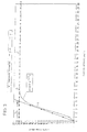
- Fig. 3 shows in detail, in a co-ordinate system having the tread depth shown on the Y axis and the tread block length shown in the t axis, the shape of an exponential function for the optimisation of treads, with the tread block chamfering of a standard tread block being shown as marked with rectangles and with the shape of a tread block boundary surface 6 in accordance with the invention being entered in relation thereto and marked with triangles.
- any profile can be optimised by means of the variables t, a, b and ⁇ with regard to the already mentioned advantages which can be aimed at specifically in an individual case. This can be done both in the circumferential or lateral direction or in a combination of both directions.
- a rectangular or also a trapezoid tread block plateau 3 can result between the start of the leading and the trailing edge lowerings in an elevated view.
- the depth of the grooves separating the tread blocks from one another in the direction of the tyre circumference is selected differently in a pre-determinable repetition sequence, in particular if alternating grooves of full depth and half depth are provided.
- Such a design primarily has a positive effect in special uses of the tyres with corresponding treads in the construction area, in stone quarries and, for example, also on refuse collection vehicles.
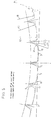
- Fig. 4 shows a first aspect of a tread design in the outer shoulder of a vehicle tyre, with the drawn-in groove angle at the leading edge of the tread, i.e. as the tread runs into the tyre contact patch 11, being 17° in the tread blocks 9 modified in accordance with the invention, in comparison to the standard tread block 8 and 11° at the trailing edge of the tread.
- the mould radius is indicated here with the reference numeral 10.
- the type of lowering, or design of the tread block boundary surfaces 6, is effected here so that the tread block boundary surface 6 at the tread entry is composed of a flat inclined surface and a surface curved in accordance with a pre-determinable radius which then merges into the central plateau 3.
- the transition between the flat tread block boundary surface starting from the groove base and the surface running in accordance with a radius and leading to the central plateau has an edged form.
- the embodiment of Fig. 5 essentially differs from the embodiment of Fig. 4 by different grooves angles at the tread entry and the tread run-out, with the special feature to be seen in the combination of a relatively large tread entry angle with a groove angle of 0° at the tread run-out.
- the tread edges of the tread block modified in accordance with the invention are also lowered relative to the tread edges of the standard tread block.
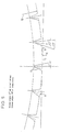
- Fig. 6 shows a further embodiment with respect to the tread designs of Figs. 4 and 5, with a lowering of the tread blocks being provided only at the tread entry side in comparison to the standard tread block shown by a broken line and with the tread block boundary surface 6 being formed by an inclined surface essentially starting from the groove base and a shorter inclined surface of greater inclination achieved by edge cut-off.
Landscapes
- Engineering & Computer Science (AREA)
- Mechanical Engineering (AREA)
- Tires In General (AREA)
Description
- The invention relates to a vehicle tyre having a profiled tread, having tread blocks in at least some regions of its circumference.
- It is known, in particular for so-called block treads, but also for treads having a relatively large proportion of tread blocks with a surface radius based on the tyre diameter or the mould radius, that irregular wear in the form of heel and toe wear frequently occurs. This heel and toe wear can occur in a particularly severe manner in treads used on the driven axles of trucks. While known tread block designs having correspondingly sharp tread block edges produce good grip values, loud rolling noise has to be accepted in addition to the disadvantage or irregular wear, and the small compression zone occurring at the relevant tread block leads to high contact pressure and to tread deformation in the leading edge, which can, in turn, result in higher flexing work, an increase in temperature, unstable rolling and a lower service life.
- It is already known from
EP 0 895 876 A2 to reduce these disadvantages by designing the corner regions of the tread blocks in a chamfered manner and thus to reduce the tread block height in the corner regions. While this measure can provide certain improvements, it does not solve the problems listed above to the required extent. - JP-A-07186623 discloses a vehicle tyre having a profiled tread with tread blocks wherein tread block edges running into the tyre contact patch are lowered over their entire length with respect to the central plateau of the tread block.
It corresponds to the preamble ofclaim 1. - US-A-5358022, JP-A-03178809 and EP-A-0925957 show similar vehicle tyres with the contour of the tread block boundary surface extending from the lowering to the base in the form of an extended S-curve for instance.
- It is the object of the present invention to provide in a vehicle pneumatic tyre having a profiled tread, and tread blocks in at least some regions of its circumference, a tread block design which avoids irregular wear in the form of heel and toe wear, leads to a substantial reduction in rolling noise, reduces the rolling resistance and increases the service life and so the running performance of the tyre.
- According to the present invention this object is essentially solved by providing at least some of the tread blocks by at least the tread block edges running into the tyre contact patch and extending at an angle to the central plane of the tyre being lowered over their entire length with respect to the central plateau of the respective tread block.
- The contour of the tread block boundary surface or surfaces extending from the start of the lowering preferably up to the base of the groove preferably extends in section planes parallel to the central plane of the tyre, in accordance with an exponential function.
- This design of treads can be used in the best possible manner for all purposes by, in particular, the selection of optimised exponential functions, with it being of particular importance that in accordance with the invention and in contrast to known measures that the tread design is executed in an optimum manner right from the groove base, with the parameters of the exponential function being capable of being selected so that both a directional dependence of the tread on the running direction and a lack of directional dependence of the tread on the running direction result.
- Particularly advantageous features and aspects of the invention are given in the dependent claims and are described with reference to embodiments with reference to the drawings in which:
- Fig. 1
- shows a schematic representation to explain the tread modification in accordance with the invention in respect to a standard tread profile;
- Fig. 2
- shows a representation of a special case of Fig. 1;
- Fig. 3
- shows a detailed representation of an exponential function for tread optimisation in accordance with the invention; and
- Figs. 4, 5 and 6
- show schematic representations of various aspects of tread block designs in the outer shoulder of tyres.
- Fig. 1 shows, in a co-ordinate system having a Y axis corresponding to the tread depth and a t axis corresponding to the tread block length, a
tread block 1, which is shown starting from the tread base as a standard tread block in the form of a broken line and in a solid line as a tread block in accordance with the invention. - The standard tread block has sharp-edged
tread block edges 2 which lead to high rolling noise in operation. Due to the edged or sharp-edged design of conventional tread blocks, a small compression zone is produced in theedge region 2 which leads to high contact pressure and tread deformation in the leading edge. Due to the high flexing work which then occurs and to the associated increase in temperature, decreases in service life result and, furthermore, uneven rolling behaviour can occur. It has already been emphasised that with such a tread block design the good grip has to be acquired at the expense of the so-called heel and toe wear. - The
tread block 1 designed in accordance with the invention and shown by solid lines differs from the standard tread block above all by the fact that thetread block edges 2 are lowered over their entire length with respect of thecentral plateau 3 and the contour of the treadblock boundary surface 6 extending from thestart 4 of the lowering, preferably up to thegroove base 5, extends in section planes parallel to the central plane of the tyre in accordance with the representation in Fig. 1 in accordance with an exponential function, i.e. the tread design is designed in an optimum manner right from the groove base. - Fig. 1 shows the general case of the tread block design in accordance with the invention, in accordance with which the start of the tread
block boundary surface 6 running in accordance with an exponential function can also be varied with respect to the tread base, as is shown by the parameter b. - The exponential function relating to this general case can be given as follows:

- The value τ is given by the distance of the intersection of the tangent at the tread
block boundary surface 6 at t = 0 and the Y axis. - The representation in Fig. 2 corresponds essentially to the representation of Fig. 1; however, it relates to the special case of b = 0, i.e. the special shape of the tread block boundary surface designed in accordance with the invention extending up to the
groove base 5. - The leading and trailing
boundary surfaces 6 of the tread blocks can have the same or different designs with regard to their shapes and/or inclinations. The trailing boundary surfaces are preferably steeper. - In addition to the predominantly desired largest possible elimination of heel and toe wear, the design of tread blocks in accordance with the invention also achieves a high reduction in rolling noise and a reduction in the rolling resistance. Due to the shape of the tread
block boundary surfaces 6, a relatively large compression zone is achieved which, in turn, leads to a low contact pressure with low tread deformation in the leading edge. This results in a reduction in flexing work and temperature so that the service life and the running performance is also increased with a good wear pattern. Another advantage which must be mentioned is that the design allows both a reduction in groove cracking and a minimisation of the block/tread striking contact to be achieved. - Fig. 3 shows in detail, in a co-ordinate system having the tread depth shown on the Y axis and the tread block length shown in the t axis, the shape of an exponential function for the optimisation of treads, with the tread block chamfering of a standard tread block being shown as marked with rectangles and with the shape of a tread
block boundary surface 6 in accordance with the invention being entered in relation thereto and marked with triangles. It has already been pointed out that any profile can be optimised by means of the variables t, a, b and τ with regard to the already mentioned advantages which can be aimed at specifically in an individual case. This can be done both in the circumferential or lateral direction or in a combination of both directions. Using these design possibilities, a rectangular or also a trapezoidtread block plateau 3 can result between the start of the leading and the trailing edge lowerings in an elevated view. - It can be of special advantage if the depth of the grooves separating the tread blocks from one another in the direction of the tyre circumference is selected differently in a pre-determinable repetition sequence, in particular if alternating grooves of full depth and half depth are provided. Such a design primarily has a positive effect in special uses of the tyres with corresponding treads in the construction area, in stone quarries and, for example, also on refuse collection vehicles.
- Fig. 4 shows a first aspect of a tread design in the outer shoulder of a vehicle tyre, with the drawn-in groove angle at the leading edge of the tread, i.e. as the tread runs into the
tyre contact patch 11, being 17° in thetread blocks 9 modified in accordance with the invention, in comparison to thestandard tread block reference numeral 10. - With this tread design, it is the lowering of the tread block edges in comparison to the standard tread block which is important, with this lowering being effected over the entire width of the tread block.
- The type of lowering, or design of the tread
block boundary surfaces 6, is effected here so that the treadblock boundary surface 6 at the tread entry is composed of a flat inclined surface and a surface curved in accordance with a pre-determinable radius which then merges into thecentral plateau 3. In the embodiment according to Fig. 4, at the tread run-out, the transition between the flat tread block boundary surface starting from the groove base and the surface running in accordance with a radius and leading to the central plateau has an edged form. - The embodiment of Fig. 5 essentially differs from the embodiment of Fig. 4 by different grooves angles at the tread entry and the tread run-out, with the special feature to be seen in the combination of a relatively large tread entry angle with a groove angle of 0° at the tread run-out. However, in this design, the tread edges of the tread block modified in accordance with the invention are also lowered relative to the tread edges of the standard tread block.
- Fig. 6 shows a further embodiment with respect to the tread designs of Figs. 4 and 5, with a lowering of the tread blocks being provided only at the tread entry side in comparison to the standard tread block shown by a broken line and with the tread
block boundary surface 6 being formed by an inclined surface essentially starting from the groove base and a shorter inclined surface of greater inclination achieved by edge cut-off. -
- 1
- Tread block
- 2
- Tread block edges
- 3
- Central plateau
- 4
- Start of lowering
- 5
- Groove base
- 6
- Tread block boundary surface
- 7
- Groove
- 8
- Standard tread block
- 9
- Modified tread block
- 10
- Surface radius
- 11
- Tyre contact patch
Claims (12)
- A vehicle tyre having a profiled tread, and having tread blocks (1) in at least some regions of its circumference, wherein for at least some of the tread blocks (1) at least the tread block edges (2) running into the tyre contact patch (11) and extending at an angle to the central plane of the tyre are lowered over their entire length with respect to the central plateau (3) of the respective tread block (1), characterised in that the contour of the tread block boundary surface (6) extending from the start (4) of the lowering, preferably up to the groove base (5), extends in section planes parallel to the central plane of the tyre in accordance with an exponential function.
- A vehicle tyre in accordance with claim 1, characterised in that the exponential function is defined by the formula

with the parameters a, b, τ being freely selectable and defined by the associated Figures. - A vehicle tyre in accordance with one of the preceding claims, characterised in that the tread block edges running out of the tyre contact patch are formed analogously to the entry edges.
- A vehicle tyre in accordance with claim 3, characterised in that the profiles of the entry and run-out boundary surfaces (6) of the tread blocks, which each at least substantially follow an exponential function in shape are designed differently with respect to their shape and/or inclination.
- A vehicle tyre in accordance with claim 4, characterised in that the run-out boundary surfaces (6) extend more steeply than the entry boundary surfaces.
- A vehicle tyre in accordance with one of the preceding claims, characterised in that the lowering of the tread block plateau disposed between the entry side and exit side amounts to approximately 20% to 80% and preferably about 30% to 50% of the block length.
- A vehicle tyre in accordance with one of the preceding claims, characterised in that the tread block plateau (3) between the start of the entry side and exit side lowering is rectangular or trapezium-shaped in plan view.
- A vehicle tyre in accordance with one of the preceding claims, characterised in that the steepness of the entry side and/or exit side tread block boundary surface (6) differs over their width.
- A vehicle tyre in accordance with one of the preceding claims, characterised in that the depth of the grooves (7) which separate the tread blocks (1) from one another in the circumferential direction of the tyre differs in a pre-determinable repetition sequence.
- A vehicle tyre in accordance with claim 9, characterised in that a groove (7) of pre-determinable depth is respectively followed by a groove (7) of smaller depth, with a change preferably being provided between a groove (7) of full depth and a groove of half depth.
- A vehicle tyre, in accordance with one of the preceding claims, characterised in that the groove angle in the tread entry is disposed in the range between 15' and 25' and the tread run-out angle is disposed in the range from 0' to 13'.
- A vehicle tyre in accordance with claim 11, characterised in that at least the entry side tread block boundary surface (6) is formed substantially as an essentially flat inclined surface starting from the base of the groove which merges in the upper quarter of the tread block height via a pre-determinable radius or a broken entry edge into the tread block plateau (3).
Applications Claiming Priority (3)
| Application Number | Priority Date | Filing Date | Title |
|---|---|---|---|
| DE19937067A DE19937067A1 (en) | 1999-08-05 | 1999-08-05 | Vehicle tires with a tread pattern |
| DE19937067 | 1999-08-05 | ||
| PCT/EP2000/006919 WO2001010657A1 (en) | 1999-08-05 | 2000-07-20 | A vehicle tyre having a profiled tread |
Publications (2)
| Publication Number | Publication Date |
|---|---|
| EP1119460A1 EP1119460A1 (en) | 2001-08-01 |
| EP1119460B1 true EP1119460B1 (en) | 2006-08-16 |
Family
ID=7917386
Family Applications (1)
| Application Number | Title | Priority Date | Filing Date |
|---|---|---|---|
| EP00954540A Expired - Lifetime EP1119460B1 (en) | 1999-08-05 | 2000-07-20 | A vehicle tyre having a profiled tread |
Country Status (6)
| Country | Link |
|---|---|
| US (1) | US6889733B2 (en) |
| EP (1) | EP1119460B1 (en) |
| JP (1) | JP4482205B2 (en) |
| AU (1) | AU6696100A (en) |
| DE (2) | DE19937067A1 (en) |
| WO (1) | WO2001010657A1 (en) |
Families Citing this family (13)
| Publication number | Priority date | Publication date | Assignee | Title |
|---|---|---|---|---|
| FR2828134A1 (en) * | 2001-08-06 | 2003-02-07 | Michelin Soc Tech | Pneumatic tire tread has blocks formed by lengthwise and transverse grooves and having surfaces of predetermined shape |
| WO2004011282A1 (en) * | 2002-07-30 | 2004-02-05 | Bridgestone Corporation | Pneumatic tire |
| CN100335300C (en) * | 2002-09-10 | 2007-09-05 | 横滨橡胶株式会社 | Pneumatic tire |
| JP4309119B2 (en) * | 2002-12-03 | 2009-08-05 | 横浜ゴム株式会社 | Pneumatic tire |
| FR2878190B1 (en) * | 2004-11-24 | 2007-01-12 | Michelin Soc Tech | CROSS-SECTIONAL BEARING GROOVE GROOVE PROFILE |
| JP4868578B2 (en) * | 2006-04-13 | 2012-02-01 | 東洋ゴム工業株式会社 | Pneumatic tire |
| JP2008155817A (en) * | 2006-12-25 | 2008-07-10 | Bridgestone Corp | Pneumatic tire for heavy load |
| US20100154948A1 (en) * | 2008-12-22 | 2010-06-24 | Goodyear Tire & Rubber Company | Tire tread with groove reinforcement |
| US20110079334A1 (en) * | 2009-10-02 | 2011-04-07 | Andreas Bott | Tire tread having improved contact pressure distribution |
| US9278582B2 (en) | 2010-12-21 | 2016-03-08 | Bridgestone Americas Tire Operations, Llc | Tire tread having developing grooves |
| US8689843B2 (en) * | 2011-12-14 | 2014-04-08 | Bridgestone Americas Tire Operations, Llc | Snow performance peaks |
| WO2018229578A1 (en) * | 2017-06-12 | 2018-12-20 | Pirelli Tyre S.P.A. | Tyre for vehicle wheels |
| DE102021002779A1 (en) | 2021-05-28 | 2022-12-01 | Mercedes-Benz Group AG | vehicle tires |
Family Cites Families (24)
| Publication number | Priority date | Publication date | Assignee | Title |
|---|---|---|---|---|
| FR2312385A1 (en) * | 1975-05-30 | 1976-12-24 | Uniroyal | TREAD STRUCTURE AND PNEUMATIC BANDAGE WRAP WITH APPLICATION |
| US4722378A (en) * | 1986-05-19 | 1988-02-02 | The Goodyear Tire & Rubber Company | Tire treads with convex elements |
| JP2819510B2 (en) * | 1988-11-04 | 1998-10-30 | 住友ゴム工業 株式会社 | Car tires |
| JPH0332907A (en) * | 1989-06-30 | 1991-02-13 | Yokohama Rubber Co Ltd:The | Pneumatic tire |
| JP2900271B2 (en) | 1989-12-07 | 1999-06-02 | 横浜ゴム株式会社 | Radial tires for heavy loads |
| US5127455A (en) * | 1990-09-28 | 1992-07-07 | Michelin Recherche Et Technique | Drive axle truck tire |
| DE4107051A1 (en) | 1991-03-06 | 1992-09-10 | Uniroyal Englebert Gmbh | Low noise tyre tread profile - has series of blocks of different sizes separated by grooves of different depths, some of which are also e.g. stepped |
| US5358022A (en) * | 1991-03-08 | 1994-10-25 | The Goodyear Tire & Rubber Company | Pneumatic tire having improved wet traction |
| CA2054991A1 (en) * | 1991-03-08 | 1992-09-09 | William Eugene Glover | Tire with improved irregular wear properties |
| JP2799127B2 (en) * | 1992-08-25 | 1998-09-17 | 住友ゴム工業株式会社 | Pneumatic tire |
| JPH06166304A (en) * | 1992-09-22 | 1994-06-14 | Bridgestone Corp | Pneumatic tire |
| AT400238B (en) * | 1992-09-24 | 1995-11-27 | Semperit Ag | TIRES |
| EP0602989A1 (en) * | 1992-12-16 | 1994-06-22 | Sumitomo Rubber Industries, Co. Ltd | Pneumatic tyre |
| EP0605849B1 (en) * | 1992-12-30 | 1996-06-26 | Michelin Recherche Et Technique S.A. | Tire tread to compensate residual aligning torque |
| JPH07101209A (en) * | 1993-10-01 | 1995-04-18 | Yokohama Rubber Co Ltd:The | Pneumatic radial tires |
| JP3533246B2 (en) * | 1993-11-05 | 2004-05-31 | 株式会社ブリヂストン | Pneumatic tire |
| JPH07186623A (en) * | 1993-12-27 | 1995-07-25 | Yokohama Rubber Co Ltd:The | Pneumatic tire |
| DE4416435A1 (en) * | 1994-05-10 | 1996-02-01 | Uniroyal Englebert Gmbh | Tread pattern |
| FR2720979A1 (en) * | 1994-06-14 | 1995-12-15 | Michelin & Cie | Tyre tread form, with improved grip in dry and wet conditions, |
| JPH092019A (en) | 1995-06-14 | 1997-01-07 | Bridgestone Corp | Pneumatic tire with directional high inclination groove |
| JP3597005B2 (en) | 1997-01-22 | 2004-12-02 | 横浜ゴム株式会社 | Pneumatic radial tire for heavy loads |
| JPH1148719A (en) * | 1997-08-07 | 1999-02-23 | Bridgestone Corp | Heavy duty pneumatic tires |
| JP3869102B2 (en) * | 1997-12-25 | 2007-01-17 | 株式会社ブリヂストン | Pneumatic tire |
| JP3967820B2 (en) * | 1998-03-18 | 2007-08-29 | 株式会社ブリヂストン | Pneumatic tire |
-
1999
- 1999-08-05 DE DE19937067A patent/DE19937067A1/en not_active Withdrawn
-
2000
- 2000-07-20 EP EP00954540A patent/EP1119460B1/en not_active Expired - Lifetime
- 2000-07-20 AU AU66961/00A patent/AU6696100A/en not_active Abandoned
- 2000-07-20 WO PCT/EP2000/006919 patent/WO2001010657A1/en not_active Ceased
- 2000-07-20 DE DE60030087T patent/DE60030087T2/en not_active Expired - Fee Related
- 2000-07-20 US US09/806,824 patent/US6889733B2/en not_active Expired - Fee Related
- 2000-07-25 JP JP2000224215A patent/JP4482205B2/en not_active Expired - Fee Related
Also Published As
| Publication number | Publication date |
|---|---|
| DE19937067A1 (en) | 2001-02-08 |
| US6889733B2 (en) | 2005-05-10 |
| DE60030087D1 (en) | 2006-09-28 |
| AU6696100A (en) | 2001-03-05 |
| DE60030087T2 (en) | 2007-03-01 |
| EP1119460A1 (en) | 2001-08-01 |
| WO2001010657A1 (en) | 2001-02-15 |
| JP4482205B2 (en) | 2010-06-16 |
| US20020166615A1 (en) | 2002-11-14 |
| JP2001055015A (en) | 2001-02-27 |
Similar Documents
| Publication | Publication Date | Title |
|---|---|---|
| US5337815A (en) | Pneumatic tire having improved wet traction | |
| EP1864830B1 (en) | Pneumatic tire | |
| US4423760A (en) | Tire tread with zig-zag grooves having groove sidewalls of varying degrees of support | |
| US6196288B1 (en) | Siping geometry to delay the onset of rib edge wear in truck tires | |
| RU2663262C1 (en) | Pneumatic tyre | |
| US6889733B2 (en) | Vehicle tire having profiled tread including blocks | |
| US20070240801A1 (en) | Pneumatic Tire | |
| EP1533142A1 (en) | Tire tread with anti-puncture pads | |
| JPH05319029A (en) | Pneumatic radial tires for heavy loads | |
| KR20010022933A (en) | Tire having sacrificial bridging | |
| EP0342908A2 (en) | Pneumatic tyre | |
| JP2002248906A (en) | Tread pattern for radial carcass tires | |
| JPH07121645B2 (en) | Pneumatic tire | |
| US5010935A (en) | Agricultural tire and tread lug therefor | |
| JPH06171316A (en) | Pneumatic radial tire for heavy load | |
| US7350552B2 (en) | Directional tread having incisions of varying inclination | |
| CN104339986B (en) | Pneumatic belt tire | |
| JPH05178015A (en) | Pneumatic radial tire for heavy load | |
| US6604564B1 (en) | Tread pattern motif for a tread | |
| EP1918130A1 (en) | Pneumatic tire | |
| EP1685982B1 (en) | Pneumatic tire | |
| JPH06320914A (en) | Pneumatic radial tire for heavy load | |
| JPH03506A (en) | Pneumatic tire whose shoulder portion partial wear is reduced | |
| JPH0796716A (en) | Pneumatic tire for heavy load | |
| JP3372340B2 (en) | Pneumatic tire |
Legal Events
| Date | Code | Title | Description |
|---|---|---|---|
| PUAI | Public reference made under article 153(3) epc to a published international application that has entered the european phase |
Free format text: ORIGINAL CODE: 0009012 |
|
| 17P | Request for examination filed |
Effective date: 20010309 |
|
| AK | Designated contracting states |
Kind code of ref document: A1 Designated state(s): AT BE CH CY DE DK ES FI FR GB GR IE IT LI LU MC NL PT SE |
|
| AX | Request for extension of the european patent |
Free format text: AL;LT;LV;MK;RO;SI |
|
| RAP1 | Party data changed (applicant data changed or rights of an application transferred) |
Owner name: DUNLOP GMBH & CO. KG |
|
| RBV | Designated contracting states (corrected) |
Designated state(s): DE FR GB |
|
| 17Q | First examination report despatched |
Effective date: 20050203 |
|
| GRAP | Despatch of communication of intention to grant a patent |
Free format text: ORIGINAL CODE: EPIDOSNIGR1 |
|
| GRAS | Grant fee paid |
Free format text: ORIGINAL CODE: EPIDOSNIGR3 |
|
| GRAA | (expected) grant |
Free format text: ORIGINAL CODE: 0009210 |
|
| AK | Designated contracting states |
Kind code of ref document: B1 Designated state(s): DE FR GB |
|
| REG | Reference to a national code |
Ref country code: GB Ref legal event code: FG4D |
|
| REF | Corresponds to: |
Ref document number: 60030087 Country of ref document: DE Date of ref document: 20060928 Kind code of ref document: P |
|
| ET | Fr: translation filed | ||
| PLBE | No opposition filed within time limit |
Free format text: ORIGINAL CODE: 0009261 |
|
| STAA | Information on the status of an ep patent application or granted ep patent |
Free format text: STATUS: NO OPPOSITION FILED WITHIN TIME LIMIT |
|
| 26N | No opposition filed |
Effective date: 20070518 |
|
| PGFP | Annual fee paid to national office [announced via postgrant information from national office to epo] |
Ref country code: FR Payment date: 20070706 Year of fee payment: 8 |
|
| PGFP | Annual fee paid to national office [announced via postgrant information from national office to epo] |
Ref country code: DE Payment date: 20080731 Year of fee payment: 9 |
|
| PGFP | Annual fee paid to national office [announced via postgrant information from national office to epo] |
Ref country code: GB Payment date: 20080616 Year of fee payment: 9 |
|
| REG | Reference to a national code |
Ref country code: FR Ref legal event code: ST Effective date: 20090331 |
|
| REG | Reference to a national code |
Ref country code: GB Ref legal event code: 732E Free format text: REGISTERED BETWEEN 20090521 AND 20090527 |
|
| PG25 | Lapsed in a contracting state [announced via postgrant information from national office to epo] |
Ref country code: FR Free format text: LAPSE BECAUSE OF NON-PAYMENT OF DUE FEES Effective date: 20080731 |
|
| GBPC | Gb: european patent ceased through non-payment of renewal fee |
Effective date: 20090720 |
|
| PG25 | Lapsed in a contracting state [announced via postgrant information from national office to epo] |
Ref country code: GB Free format text: LAPSE BECAUSE OF NON-PAYMENT OF DUE FEES Effective date: 20090720 |
|
| PG25 | Lapsed in a contracting state [announced via postgrant information from national office to epo] |
Ref country code: DE Free format text: LAPSE BECAUSE OF NON-PAYMENT OF DUE FEES Effective date: 20100202 |