EP1119438B1 - A gamma ray collimator build-up - Google Patents
A gamma ray collimator build-up Download PDFInfo
- Publication number
- EP1119438B1 EP1119438B1 EP99949499A EP99949499A EP1119438B1 EP 1119438 B1 EP1119438 B1 EP 1119438B1 EP 99949499 A EP99949499 A EP 99949499A EP 99949499 A EP99949499 A EP 99949499A EP 1119438 B1 EP1119438 B1 EP 1119438B1
- Authority
- EP
- European Patent Office
- Prior art keywords
- partial
- boundary
- boundary surfaces
- holes
- partial bodies
- Prior art date
- Legal status (The legal status is an assumption and is not a legal conclusion. Google has not performed a legal analysis and makes no representation as to the accuracy of the status listed.)
- Expired - Lifetime
Links
Images


Classifications
-
- G—PHYSICS
- G21—NUCLEAR PHYSICS; NUCLEAR ENGINEERING
- G21K—HANDLING OF PARTICLES OR IONISING RADIATION NOT OTHERWISE PROVIDED FOR; IRRADIATION DEVICES; GAMMA RAY OR X-RAY MICROSCOPES
- G21K1/00—Arrangements for handling particles or ionising radiation, e.g. focusing or moderating
- G21K1/02—Arrangements for handling particles or ionising radiation, e.g. focusing or moderating using diaphragms, collimators
- G21K1/025—Arrangements for handling particles or ionising radiation, e.g. focusing or moderating using diaphragms, collimators using multiple collimators, e.g. Bucky screens; other devices for eliminating undesired or dispersed radiation
-
- A—HUMAN NECESSITIES
- A61—MEDICAL OR VETERINARY SCIENCE; HYGIENE
- A61N—ELECTROTHERAPY; MAGNETOTHERAPY; RADIATION THERAPY; ULTRASOUND THERAPY
- A61N5/00—Radiation therapy
- A61N5/10—X-ray therapy; Gamma-ray therapy; Particle-irradiation therapy
- A61N5/1077—Beam delivery systems
- A61N5/1084—Beam delivery systems for delivering multiple intersecting beams at the same time, e.g. gamma knives
-
- Y—GENERAL TAGGING OF NEW TECHNOLOGICAL DEVELOPMENTS; GENERAL TAGGING OF CROSS-SECTIONAL TECHNOLOGIES SPANNING OVER SEVERAL SECTIONS OF THE IPC; TECHNICAL SUBJECTS COVERED BY FORMER USPC CROSS-REFERENCE ART COLLECTIONS [XRACs] AND DIGESTS
- Y10—TECHNICAL SUBJECTS COVERED BY FORMER USPC
- Y10T—TECHNICAL SUBJECTS COVERED BY FORMER US CLASSIFICATION
- Y10T29/00—Metal working
- Y10T29/49—Method of mechanical manufacture
- Y10T29/496—Multiperforated metal article making
-
- Y—GENERAL TAGGING OF NEW TECHNOLOGICAL DEVELOPMENTS; GENERAL TAGGING OF CROSS-SECTIONAL TECHNOLOGIES SPANNING OVER SEVERAL SECTIONS OF THE IPC; TECHNICAL SUBJECTS COVERED BY FORMER USPC CROSS-REFERENCE ART COLLECTIONS [XRACs] AND DIGESTS
- Y10—TECHNICAL SUBJECTS COVERED BY FORMER USPC
- Y10T—TECHNICAL SUBJECTS COVERED BY FORMER US CLASSIFICATION
- Y10T29/00—Metal working
- Y10T29/49—Method of mechanical manufacture
- Y10T29/49826—Assembling or joining
- Y10T29/49893—Peripheral joining of opposed mirror image parts to form a hollow body
Definitions
- the present invention relates to a method of providing with precision a number of long and narrow through holes in a body made of a high-density material.
- the invention relates to the production of an integrated multichannel collimator for use in a device for radiation treatment of a human being or an animal, for instance, ELEKTA AB's gamma knife.
- An object of the present invention is to provide a method of producing with flexibility and great precision a number of long through holes with an optional, small diameter in a body made of a material which is difficult to machine.
- Another object of the invention is to provide a comparatively inexpensive and functional method of producing long, narrow holes in a high-density material.
- a further object of the invention is to provide a method which allows production of elongated holes with an optional section in the transverse as well as the longitudinal direction.
- each partial body is defined by an outer surface, which is part of the outer surface of the entire body, an inner surface, which is part of the inner surface of the entire body, as well as a pair of boundary surfaces, which extend from the outer surface to the inner surface, that said holes are produced by machining at least one of the boundary surfaces of adjacent partial bodies, each hole extending from the outer surface to the inner surface along said at least one boundary surface, and that the thus machined partial bodies are fixedly attached to each other.
- the method according to the invention may advantageously be applied in most situations, in which a number of long and narrow holes or channels are to be produced with precision in a body made of a hard material or of a high-density material or metal, such as tungsten, uranium, cobalt and iridium.
- a multichannel collimator for use in a device for radiation treatment of a human being or an animal, such as ELEKTA AB's gamma knife. Therefore, reference is made to Swedish patent 8602025-2 (US-A-4,780,898, EP 7850124.7).
- the collimator is a body in the form of a substantially semispherical, thick shell or a dome.
- the wall thickness is preferably about 200 mm and the number of the holes about 200.
- the diameter of the holes is 1-8 mm.
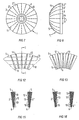
- a first embodiment of a collimator is illustrated, which is produced by the method according to the invention.
- the body 1 is produced in the form of a number of partial bodies 2, which are arranged close to each other and form the body 1.
- the partial bodies are fixedly attached to each other, for instance, by soldering and/or by means of a surrounding cover 3, which is indicated by broken lines in Fig. 4.
- Each partial body 2 is formed as an annular disc, which is rotationally symmetrical about the axis of symmetry 4 of the body 1, and each disc has a cone angle different from that of the other discs (see Fig. 2).
- each partial body 2 is defined by an outer surface 5, which is part of the outer surface of the entire body 1, an inner surface 6, which is part of the inner surface of the entire body 1, as well as a pair of conical boundary surfaces 7 and 8, which extend from the outer surface 5 to the inner surface 6.
- the boundary surfaces 7 and 8, by means of which the partial bodies 2 abut against each other, are substantially directed towards the centre 9 of the dome (towards the centre of the sphere which has given its shape to the semispherical shell), cf. Fig. 1.
- one half or groove 10 of the beam channel 11 is produced in the boundary surface 7 of one of the partial bodies 2', whereas the other half or groove 10 of the channel is produced in the adjoining boundary surface 8 of the adjacent partial body 2", opposite to the first-mentioned half or groove so that they define the channel 11 together (cf. Fig. 3).
- a groove 10 is produced only in the boundary surface 8 of one of the partial bodies 2", the channel 11 being defined by the groove 10 in one of the boundary surfaces 8 and the opposite, unmachined portion in the boundary surface 7 of the adjacent partial body 2', as shown in Fig. 6.
- the cross-sectional shape of the holes or the channels 11 can be designed as desired and have various profiles, for instance, circular, semicircular, oval, triangular, rectangular (see Figs 5 and 6), due to the fact that the grooves 10 are produced by machining the boundary surfaces 7, 8 of the partial bodies 2.
- the longitudinal profile of the channels 11, i.e. from the outer surface 5 to the inner surface 6, may be designed as desired, for instance, of uniform thickness, continuously or stepwise tapered.
- the channels 11 are shown with an increasing cross-section from the outer surface 5 towards the inner surface 6.
- the grooves 10 are thus made by machining the boundary surfaces 7 and/or 8 of the partial bodies 2.
- the machining may be carried out by milling, grinding, spark machining and/or planing.
- the collimator is made of lead, the lead must be encapsulated (cf. the cover 3 in Fig. 4).
- the collimator could also be made of iron.
- the grooves 10 in the partial bodies 2 are made larger, inserts of tungsten, uranium, cobalt, iridium or the like with beam channels machined as described above being arranged in a suitable manner in the grooves.
- the rotationally symmetrical discs have the best possible geometrical shape for the intended production (cutting) and can easily be assembled with maintained geometrical precision.
- the production method is comparatively inexpensive and easy, and the partial bodies can be made of materials out of which it would have been difficult to produce an entire massive body (a collimator of prior-art design with bored holes).
- Figs 7-11 an alternative embodiment of the invention is illustrated. It differs from the above-described embodiment primarily in that the partial bodies 2, 2', 2" are not made as conical, annular discs but as "semisegments of an orange", that is the partial bodies 2 of the body 1 are formed as identical sector segments with their boundary surfaces 7 and 8 directed towards the axis of symmetry 4 of the body 2 (cf. in particular Figs 7 and 11).
- the grooves 10 of the holes 11, which also in this case are machined in the boundary surfaces 7 and/or 8 of the partial bodies 2, 2', 2" are arranged in a common plane for each boundary surface 7, 8, each such plane extending through said axis of symmetry 4 (cf. Fig. 7).
- the holes 11 are produced and formed as stated in connection with the first-mentioned embodiment.
- the orange segment model comprises a greater number of partial bodies having dimensions which are more advantageous in terms of production-technique, and has the same accessibility to the open channels.
- the principle and basis of the collimator is thus to (systematically) divide the body of the collimator into a number of selected section planes, which all cut the focal point of the collimator, and to arrange a number of open channels in the boundary surfaces of the partial bodies, said channels being oriented towards the same focal point.
- the partial bodies When assembled, the partial bodies together form a closed collimator having focussed closed channels or grooves.
- the boundary surfaces may be identical with the focal planes or formed with small geometrical deviations from the focal planes to extinguish any radiation leaking in the lateral direction between the boundary surfaces (by inserting different seals).
- small deviations is meant (varying) distances to the focal planes in the order of the cross-section of the channels of the collimator at the (varying) focal distance in question.
- Figs 9 and 11-16 Different designs of leakage seals are schematically shown in Figs 9 and 11-16. As appears from Figs 9 and 11, the leakage sealing has been presented in connection with the "orange segment model", but a man skilled in the art will realise that it may also be applied to the "disc model”.
- the boundary surfaces 7 and 8 have a structure with circular, concentric pleats, comprising elevations 12 alternating with depressions 13 in the radial direction, since the elevations 12 and the depressions 13 are arranged as concentric circles about the axis of symmetry 4 of the body 1. All the elevations 12 of a partial body (e.g. 2') may thus be closely fit into the corresponding depressions 13 of the adjacent partial body (e.g. 2") and vice versa (cf. Figs 15 and 16).
- the boundary surfaces 7, 8 may also be corrugated, labyrinth-shaped, stepped or the like and comprise sealingly interacting elevations and depressions, respectively.
- the pleats instead of being formed as concentric circles, may thus be made, for instance, as straight, parallel lines.
- each pleat extends from the outer surface 5 of the associated partial body 2 to its inner surface 6, substantially oriented towards the axis of symmetry 4 of the partial body. This is illustrated in Fig. 13.
- Figs 15 and 16 show sections along the line C-C through a channel 11 in Fig. 12.
- the boundary surfaces are formed with triangular pleats.
- Each elevation 12 of a partial body 2' is intended to be fit into a matching depression 13 of the adjacent partial body 2" and vice versa.
- they can be rectangular, in which case the plane surface of the elevation 12 of a partial body 2', when assembling the collimator according to the invention, will abut against the plane surface of the matching depression 13 of an adjacent partial body 2" and vice versa, as shown in Fig. 16.
- the collimator may advantageously be made. If use is made of, for instance, lead or uranium, the final product should be encapsulated in a rust and corrosive resisting material because of its toxicity and for radiation safety reasons.
Landscapes
- Physics & Mathematics (AREA)
- Spectroscopy & Molecular Physics (AREA)
- Engineering & Computer Science (AREA)
- General Engineering & Computer Science (AREA)
- High Energy & Nuclear Physics (AREA)
- Measurement Of Radiation (AREA)
- Nuclear Medicine (AREA)
- Electrical Discharge Machining, Electrochemical Machining, And Combined Machining (AREA)
- Machine Tool Units (AREA)
- Turbine Rotor Nozzle Sealing (AREA)
- Radiation-Therapy Devices (AREA)
- Analysing Materials By The Use Of Radiation (AREA)
Abstract
Description
Claims (9)
- A method of providing with precision a number of long and narrow through holes (11) in a body (1) made of a high-density material, wherein the body (1) is made in the form of a number of partial bodies (2, 2', 2"), which are arranged close to each other and form said body (1), each partial body (2, 2', 2") is defined by an outer surface (5), which is part of the outer surface of the entire body (1), an inner surface (6), which is part of the inner surface of the entire body (1), as well as a pair of boundary surfaces (7, 8), which extend from the outer surface (5) to the inner surface (6), said holes (11) are produced by machining at least one of the boundary surfaces (7, 8) of adjacent partial bodies (2', 2"), each hole (11) extending from the outer surface (5) to the inner surface (6) along said at least one boundary surface (7, 8), and the thus machined partial bodies (2, 2', 2") are fixedly attached to each other.
- A method as claimed in claim 1, characterised in that each hole (11) is rectilinear and produced by milling, grinding, stamping etc a groove (10) in the boundary surface (7) of a partial body (2'), and that an interacting groove (10) is produced in the same manner in the boundary surface (8) of an adjacent partial body (2"), opposite to the first-mentioned groove, said grooves together defining the hole (11).
- A method as claimed in claim 1, characterised in that each hole (11) is produced by milling, grinding, stamping etc a groove (10) only in one of the boundary surfaces (8) of one (2") of two adjacent partial bodies (2', 2"), said hole (11) being defined by the groove (10) in one of the boundary surfaces (8) and the opposite unmachined portion of the other boundary surface (7).
- A method as claimed in claim 2 or 3, characterised in that each groove (10) is semicircular, triangular, rectangular or the like in cross-section.
- A method as claimed in claim 4, characterised in that the cross-section of the holes (11) decreases from the inner surface (6) towards the outer surface (5).
- A method as claimed in any one of the preceding claims, characterised in that the boundary surfaces (7, 8) are formed with a profile which has elevations (12) and depressions (13), an elevation (12) of a partial body (2') being closely fit into a depression (13) of an adjacent partial body (2") when assembling the body (1).
- A method as claimed in any one of the preceding claims, characterised in that the entire body (1) has substantially the form of a dome, and that each partial body (2) is formed as an annular disc with its boundary surfaces (7, 8) directed substantially towards the centre (9) of the dome.
- A method as claimed in any one of claims 1-6, characterised in that the entire body (1) has substantially the form of a dome, and that each partial body (2) is formed as an element shaped as a sector segment with its boundary surfaces (7, 8) directed towards the axis of symmetry (4) of the dome.
- A method as claimed in any one of the preceding claims, characterised in that the partial bodies (2, 2', 2") are fixedly attached to each other by soldering and/or by means of a surrounding cover.
Applications Claiming Priority (3)
| Application Number | Priority Date | Filing Date | Title |
|---|---|---|---|
| SE9803065 | 1998-09-10 | ||
| SE9803065A SE9803065L (en) | 1998-09-10 | 1998-09-10 | Process for making a jet knife collimator and using a jet knife collimator |
| PCT/SE1999/001553 WO2000018538A1 (en) | 1998-09-10 | 1999-09-07 | A gamma ray collimator build-up |
Publications (2)
| Publication Number | Publication Date |
|---|---|
| EP1119438A1 EP1119438A1 (en) | 2001-08-01 |
| EP1119438B1 true EP1119438B1 (en) | 2003-03-19 |
Family
ID=20412549
Family Applications (1)
| Application Number | Title | Priority Date | Filing Date |
|---|---|---|---|
| EP99949499A Expired - Lifetime EP1119438B1 (en) | 1998-09-10 | 1999-09-07 | A gamma ray collimator build-up |
Country Status (9)
| Country | Link |
|---|---|
| US (1) | US6763588B1 (en) |
| EP (1) | EP1119438B1 (en) |
| CN (1) | CN1134025C (en) |
| AT (1) | ATE234704T1 (en) |
| AU (1) | AU6235599A (en) |
| CA (1) | CA2341176A1 (en) |
| DE (1) | DE69906111T2 (en) |
| SE (1) | SE9803065L (en) |
| WO (1) | WO2000018538A1 (en) |
Families Citing this family (9)
| Publication number | Priority date | Publication date | Assignee | Title |
|---|---|---|---|---|
| RU2219980C2 (en) * | 2002-02-05 | 2003-12-27 | Хетеев Михаил Владимирович | Device for radiotherapy |
| US7659530B2 (en) * | 2006-08-03 | 2010-02-09 | Yanxiong Qiu | Focusing and shielding device for encephalic photon knife |
| US20080055755A1 (en) * | 2006-08-31 | 2008-03-06 | Searete Llc, A Limited Liability Corporation Of The State Of Delaware | Electromagnetic device and method |
| US20090171422A1 (en) * | 2007-12-31 | 2009-07-02 | Searete Llc , A Limited Liability Corporation Of The State Of Delaware | Radiation treatment device |
| CN102446571B (en) * | 2010-09-30 | 2014-03-05 | 上海世鹏实验室科技发展有限公司 | Self-focusing radioactive source device and radiation device thereof |
| CN107924730B (en) | 2015-06-10 | 2021-09-28 | 反射医疗公司 | High bandwidth binary multileaf collimator design |
| CN105854192B (en) * | 2016-05-31 | 2022-08-23 | 武汉瑞祥安精密制造有限责任公司 | High-precision combined gamma knife collimating body and processing method thereof |
| CN106271450B (en) * | 2016-08-31 | 2019-02-12 | 西北机器有限公司 | For processing the auxiliary mould and processing method of Type B gamma knife treatment head part |
| CN111631209B (en) * | 2020-04-29 | 2022-03-25 | 国网安徽省电力有限公司宣城供电公司 | Automatic laser calibration system for transformer substation |
Family Cites Families (10)
| Publication number | Priority date | Publication date | Assignee | Title |
|---|---|---|---|---|
| US2169937A (en) * | 1937-02-15 | 1939-08-15 | Wempe Bernhard | Method of producing perforated metal sheets |
| US3457619A (en) * | 1967-11-28 | 1969-07-29 | Gen Electric | Production of perforated metallic bodies |
| DE2351450A1 (en) * | 1973-10-11 | 1975-04-24 | Bandelin Electronic Kg | Gamma ray collimator for isotope in medical test - comprises several concentric frusto-conical heavy metal shells giving clear resolution |
| US4465540A (en) * | 1979-05-03 | 1984-08-14 | Albert Richard D | Method of manufacture of laminate radiation collimator |
| US4450706A (en) * | 1982-02-08 | 1984-05-29 | Siemens Gammasonics, Inc. | Method and apparatus for forming collimator strips |
| SE453156B (en) | 1986-04-30 | 1988-01-18 | Elekta Instr Sa | RADIATION KNIFE INCLUDING A LARGE NUMBER WITHIN A PROTECTION PROTECTED |
| US5212718A (en) * | 1991-08-06 | 1993-05-18 | The United States Of America As Represented By The Administrator Of The National Aeronautics And Space Administration | Gamma ray collimator |
| FR2694504B1 (en) | 1992-08-04 | 1994-09-16 | Joel Kerjean | Method and apparatus for the treatment of lesions by high energy radiation. |
| EP0662018B1 (en) * | 1992-09-25 | 2000-03-15 | Bhp Engineering Pty. Ltd | Hollow bars and method of manufacture |
| CN1028607C (en) | 1993-04-13 | 1995-05-31 | 宋世鹏 | Rotary cone focusing type gamma-ray radiation unit |
-
1998
- 1998-09-10 SE SE9803065A patent/SE9803065L/en not_active IP Right Cessation
-
1999
- 1999-09-07 WO PCT/SE1999/001553 patent/WO2000018538A1/en not_active Ceased
- 1999-09-07 AT AT99949499T patent/ATE234704T1/en not_active IP Right Cessation
- 1999-09-07 EP EP99949499A patent/EP1119438B1/en not_active Expired - Lifetime
- 1999-09-07 CN CNB998107921A patent/CN1134025C/en not_active Expired - Fee Related
- 1999-09-07 US US09/763,165 patent/US6763588B1/en not_active Expired - Lifetime
- 1999-09-07 CA CA002341176A patent/CA2341176A1/en not_active Abandoned
- 1999-09-07 DE DE69906111T patent/DE69906111T2/en not_active Expired - Lifetime
- 1999-09-07 AU AU62355/99A patent/AU6235599A/en not_active Abandoned
Also Published As
| Publication number | Publication date |
|---|---|
| DE69906111T2 (en) | 2003-11-06 |
| WO2000018538A1 (en) | 2000-04-06 |
| SE511538C2 (en) | 1999-10-11 |
| CN1134025C (en) | 2004-01-07 |
| US6763588B1 (en) | 2004-07-20 |
| ATE234704T1 (en) | 2003-04-15 |
| CA2341176A1 (en) | 2000-04-06 |
| DE69906111D1 (en) | 2003-04-24 |
| AU6235599A (en) | 2000-04-17 |
| SE9803065L (en) | 1999-10-11 |
| EP1119438A1 (en) | 2001-08-01 |
| SE9803065D0 (en) | 1998-09-10 |
| CN1316937A (en) | 2001-10-10 |
Similar Documents
| Publication | Publication Date | Title |
|---|---|---|
| KR100640140B1 (en) | Cutting tool assembly and its cutting inserts | |
| US4606678A (en) | Circular chip control insert | |
| KR101198052B1 (en) | Cutting insert for turning and milling | |
| US6763588B1 (en) | Gamma ray collimator build up | |
| US10036486B2 (en) | Tortuous path control valve trim | |
| US5626444A (en) | Rotary cutting tool | |
| US8500375B2 (en) | Cutting insert, in particular, for crankshaft machining | |
| US9981323B2 (en) | Double-sided tangential cutting insert and cutting tool system using the same | |
| KR20120099235A (en) | Multiteeth indexable insert with locating means and material removal tool with same | |
| BG65051B1 (en) | TANGNICAL INDEXABLE INDUCTIVE ADJUSTMENT AND CUTTING TOOL | |
| US7607867B2 (en) | Tooling insert with mating surface | |
| RU2009131309A (en) | MILLING HEAD AND CUTTING MILLING PLATE WITH COOLANT | |
| KR19990045724A (en) | Milling cutting inserts and milling tool holders | |
| JP2004515372A (en) | Metal cutting tool having vibration damping means | |
| JP2013022727A (en) | Cutting insert especially for tooth cutter | |
| RU2146986C1 (en) | Drill | |
| WO1995026246B1 (en) | Rail-wheel machining tool and method of machining sets of rail wheels | |
| IL260312A (en) | Circular cutting insert having non-circular peripheral edge | |
| KR20210059698A (en) | Method of manufacturing a block forged valve body with a fully encapsulated seat ring | |
| US5388484A (en) | Method of manufacturing diamond-impregnated drilling crowns | |
| IL144138A0 (en) | Milling cutter and cutting insert therefor | |
| JPH01103218A (en) | Ball-nose bottom milling and manufacture thereof | |
| WO2017045911A1 (en) | A cutting tool, a tool body and a method for producing a tool body | |
| RU2584625C1 (en) | Disc mill for processing narrow slots and plate therefor (versions) | |
| JPH04371374A (en) | Cutter for chip dresser and this manufacture |
Legal Events
| Date | Code | Title | Description |
|---|---|---|---|
| PUAI | Public reference made under article 153(3) epc to a published international application that has entered the european phase |
Free format text: ORIGINAL CODE: 0009012 |
|
| 17P | Request for examination filed |
Effective date: 20010210 |
|
| AK | Designated contracting states |
Kind code of ref document: A1 Designated state(s): AT BE CH CY DE DK ES FI FR GB GR IE IT LI LU MC NL PT SE |
|
| GRAH | Despatch of communication of intention to grant a patent |
Free format text: ORIGINAL CODE: EPIDOS IGRA |
|
| GRAH | Despatch of communication of intention to grant a patent |
Free format text: ORIGINAL CODE: EPIDOS IGRA |
|
| GRAA | (expected) grant |
Free format text: ORIGINAL CODE: 0009210 |
|
| AK | Designated contracting states |
Designated state(s): AT BE CH CY DE DK ES FI FR GB GR IE IT LI LU MC NL PT SE |
|
| PG25 | Lapsed in a contracting state [announced via postgrant information from national office to epo] |
Ref country code: NL Free format text: LAPSE BECAUSE OF FAILURE TO SUBMIT A TRANSLATION OF THE DESCRIPTION OR TO PAY THE FEE WITHIN THE PRESCRIBED TIME-LIMIT Effective date: 20030319 Ref country code: LI Free format text: LAPSE BECAUSE OF FAILURE TO SUBMIT A TRANSLATION OF THE DESCRIPTION OR TO PAY THE FEE WITHIN THE PRESCRIBED TIME-LIMIT Effective date: 20030319 Ref country code: IT Free format text: LAPSE BECAUSE OF FAILURE TO SUBMIT A TRANSLATION OF THE DESCRIPTION OR TO PAY THE FEE WITHIN THE PRESCRIBED TIME-LIMIT;WARNING: LAPSES OF ITALIAN PATENTS WITH EFFECTIVE DATE BEFORE 2007 MAY HAVE OCCURRED AT ANY TIME BEFORE 2007. THE CORRECT EFFECTIVE DATE MAY BE DIFFERENT FROM THE ONE RECORDED. Effective date: 20030319 Ref country code: GR Free format text: LAPSE BECAUSE OF FAILURE TO SUBMIT A TRANSLATION OF THE DESCRIPTION OR TO PAY THE FEE WITHIN THE PRESCRIBED TIME-LIMIT Effective date: 20030319 Ref country code: FI Free format text: LAPSE BECAUSE OF FAILURE TO SUBMIT A TRANSLATION OF THE DESCRIPTION OR TO PAY THE FEE WITHIN THE PRESCRIBED TIME-LIMIT Effective date: 20030319 Ref country code: CH Free format text: LAPSE BECAUSE OF FAILURE TO SUBMIT A TRANSLATION OF THE DESCRIPTION OR TO PAY THE FEE WITHIN THE PRESCRIBED TIME-LIMIT Effective date: 20030319 Ref country code: BE Free format text: LAPSE BECAUSE OF FAILURE TO SUBMIT A TRANSLATION OF THE DESCRIPTION OR TO PAY THE FEE WITHIN THE PRESCRIBED TIME-LIMIT Effective date: 20030319 Ref country code: AT Free format text: LAPSE BECAUSE OF FAILURE TO SUBMIT A TRANSLATION OF THE DESCRIPTION OR TO PAY THE FEE WITHIN THE PRESCRIBED TIME-LIMIT Effective date: 20030319 |
|
| REG | Reference to a national code |
Ref country code: GB Ref legal event code: FG4D |
|
| REG | Reference to a national code |
Ref country code: CH Ref legal event code: EP |
|
| REG | Reference to a national code |
Ref country code: IE Ref legal event code: FG4D |
|
| REF | Corresponds to: |
Ref document number: 69906111 Country of ref document: DE Date of ref document: 20030424 Kind code of ref document: P |
|
| REG | Reference to a national code |
Ref country code: SE Ref legal event code: TRGR |
|
| PG25 | Lapsed in a contracting state [announced via postgrant information from national office to epo] |
Ref country code: DK Free format text: LAPSE BECAUSE OF FAILURE TO SUBMIT A TRANSLATION OF THE DESCRIPTION OR TO PAY THE FEE WITHIN THE PRESCRIBED TIME-LIMIT Effective date: 20030619 |
|
| PG25 | Lapsed in a contracting state [announced via postgrant information from national office to epo] |
Ref country code: PT Free format text: LAPSE BECAUSE OF FAILURE TO SUBMIT A TRANSLATION OF THE DESCRIPTION OR TO PAY THE FEE WITHIN THE PRESCRIBED TIME-LIMIT Effective date: 20030620 |
|
| NLV1 | Nl: lapsed or annulled due to failure to fulfill the requirements of art. 29p and 29m of the patents act | ||
| PG25 | Lapsed in a contracting state [announced via postgrant information from national office to epo] |
Ref country code: LU Free format text: LAPSE BECAUSE OF NON-PAYMENT OF DUE FEES Effective date: 20030907 Ref country code: CY Free format text: LAPSE BECAUSE OF FAILURE TO SUBMIT A TRANSLATION OF THE DESCRIPTION OR TO PAY THE FEE WITHIN THE PRESCRIBED TIME-LIMIT Effective date: 20030907 |
|
| PG25 | Lapsed in a contracting state [announced via postgrant information from national office to epo] |
Ref country code: IE Free format text: LAPSE BECAUSE OF NON-PAYMENT OF DUE FEES Effective date: 20030908 |
|
| PG25 | Lapsed in a contracting state [announced via postgrant information from national office to epo] |
Ref country code: MC Free format text: LAPSE BECAUSE OF NON-PAYMENT OF DUE FEES Effective date: 20030930 Ref country code: ES Free format text: LAPSE BECAUSE OF FAILURE TO SUBMIT A TRANSLATION OF THE DESCRIPTION OR TO PAY THE FEE WITHIN THE PRESCRIBED TIME-LIMIT Effective date: 20030930 |
|
| REG | Reference to a national code |
Ref country code: CH Ref legal event code: PL |
|
| ET | Fr: translation filed | ||
| PLBE | No opposition filed within time limit |
Free format text: ORIGINAL CODE: 0009261 |
|
| STAA | Information on the status of an ep patent application or granted ep patent |
Free format text: STATUS: NO OPPOSITION FILED WITHIN TIME LIMIT |
|
| 26N | No opposition filed |
Effective date: 20031222 |
|
| REG | Reference to a national code |
Ref country code: IE Ref legal event code: MM4A |
|
| PGFP | Annual fee paid to national office [announced via postgrant information from national office to epo] |
Ref country code: SE Payment date: 20090916 Year of fee payment: 11 |
|
| REG | Reference to a national code |
Ref country code: SE Ref legal event code: EUG |
|
| REG | Reference to a national code |
Ref country code: FR Ref legal event code: ST Effective date: 20110531 |
|
| PG25 | Lapsed in a contracting state [announced via postgrant information from national office to epo] |
Ref country code: FR Free format text: LAPSE BECAUSE OF NON-PAYMENT OF DUE FEES Effective date: 20100930 |
|
| PGFP | Annual fee paid to national office [announced via postgrant information from national office to epo] |
Ref country code: FR Payment date: 20090921 Year of fee payment: 11 |
|
| PGFP | Annual fee paid to national office [announced via postgrant information from national office to epo] |
Ref country code: GB Payment date: 20110906 Year of fee payment: 13 |
|
| PG25 | Lapsed in a contracting state [announced via postgrant information from national office to epo] |
Ref country code: SE Free format text: LAPSE BECAUSE OF NON-PAYMENT OF DUE FEES Effective date: 20100908 |
|
| PGFP | Annual fee paid to national office [announced via postgrant information from national office to epo] |
Ref country code: DE Payment date: 20120904 Year of fee payment: 14 |
|
| GBPC | Gb: european patent ceased through non-payment of renewal fee |
Effective date: 20120907 |
|
| PG25 | Lapsed in a contracting state [announced via postgrant information from national office to epo] |
Ref country code: GB Free format text: LAPSE BECAUSE OF NON-PAYMENT OF DUE FEES Effective date: 20120907 |
|
| REG | Reference to a national code |
Ref country code: DE Ref legal event code: R119 Ref document number: 69906111 Country of ref document: DE Effective date: 20140401 |
|
| PG25 | Lapsed in a contracting state [announced via postgrant information from national office to epo] |
Ref country code: DE Free format text: LAPSE BECAUSE OF NON-PAYMENT OF DUE FEES Effective date: 20140401 |
|
| P01 | Opt-out of the competence of the unified patent court (upc) registered |
Effective date: 20230529 |