EP1119138A2 - System and method for combining Internet connections with point-to-point telephonic connections - Google Patents
System and method for combining Internet connections with point-to-point telephonic connections Download PDFInfo
- Publication number
- EP1119138A2 EP1119138A2 EP00301016A EP00301016A EP1119138A2 EP 1119138 A2 EP1119138 A2 EP 1119138A2 EP 00301016 A EP00301016 A EP 00301016A EP 00301016 A EP00301016 A EP 00301016A EP 1119138 A2 EP1119138 A2 EP 1119138A2
- Authority
- EP
- European Patent Office
- Prior art keywords
- network
- communication
- network site
- site
- telephonic
- Prior art date
- Legal status (The legal status is an assumption and is not a legal conclusion. Google has not performed a legal analysis and makes no representation as to the accuracy of the status listed.)
- Withdrawn
Links
Images
Classifications
-
- H—ELECTRICITY
- H04—ELECTRIC COMMUNICATION TECHNIQUE
- H04L—TRANSMISSION OF DIGITAL INFORMATION, e.g. TELEGRAPHIC COMMUNICATION
- H04L12/00—Data switching networks
- H04L12/54—Store-and-forward switching systems
- H04L12/56—Packet switching systems
- H04L12/5691—Access to open networks; Ingress point selection, e.g. ISP selection
- H04L12/5692—Selection among different networks
-
- H—ELECTRICITY
- H04—ELECTRIC COMMUNICATION TECHNIQUE
- H04Q—SELECTING
- H04Q3/00—Selecting arrangements
-
- H—ELECTRICITY
- H04—ELECTRIC COMMUNICATION TECHNIQUE
- H04Q—SELECTING
- H04Q2213/00—Indexing scheme relating to selecting arrangements in general and for multiplex systems
- H04Q2213/13039—Asymmetrical two-way transmission, e.g. ADSL, HDSL
-
- H—ELECTRICITY
- H04—ELECTRIC COMMUNICATION TECHNIQUE
- H04Q—SELECTING
- H04Q2213/00—Indexing scheme relating to selecting arrangements in general and for multiplex systems
- H04Q2213/13093—Personal computer, PC
-
- H—ELECTRICITY
- H04—ELECTRIC COMMUNICATION TECHNIQUE
- H04Q—SELECTING
- H04Q2213/00—Indexing scheme relating to selecting arrangements in general and for multiplex systems
- H04Q2213/13199—Modem, modulation
-
- H—ELECTRICITY
- H04—ELECTRIC COMMUNICATION TECHNIQUE
- H04Q—SELECTING
- H04Q2213/00—Indexing scheme relating to selecting arrangements in general and for multiplex systems
- H04Q2213/13298—Local loop systems, access network
-
- H—ELECTRICITY
- H04—ELECTRIC COMMUNICATION TECHNIQUE
- H04Q—SELECTING
- H04Q2213/00—Indexing scheme relating to selecting arrangements in general and for multiplex systems
- H04Q2213/13389—LAN, internet
Definitions
- This invention generally relates to telecommunication systems and methods, and more particularly, to systems and methods that communicate via a computer network such as the Internet.
- Computer networks such as the Internet are unsecure networks because they consist of a multitude of computers which are not controlled in any unified way.
- the networking technology employed by the Internet is very smart. Every time, a new computer is connected to the Internet, the Internet adopts that connection as its own and begins to route Internet traffic over that connection and through that new computer Additionally, the Internet traffic follows multiple paths through multiple computers to assure proper reception at a destination site. As more computers are connected to the Internet, the network grows exponentially.
- a method for transmitting communication signals from a elecommunication switch, via a communication network, to a network server having a network site for communication with a computer device coupled with the telecommunication system comprises the steps of connecting the telecommunication switch to the network site via the communication network and establishing a point to point path between the telecommunication switch and the network site.
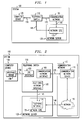
- Fig. 1 shows a functional block diagram for the communication system 100.
- the communication system 100 is shown having a computer device 105, telephonic switch 110, communication network 115, network server 120, and a network site 125.
- the computer device 105 is connected, via connection (communication link) 130, to the telephonic switch 110.
- the telephonic switch 110 is connected to the communication network 115 via connection 135
- the communication network 115 is also connected via connection 140, to the network site 125.
- the network site 125 is located on the network server 120 and is also connected to the telephonic switch 110 via connection 145.
- the telephonic switch 110 is preferably any switch that connects a central office of a telephone or cellular service provider to a computer device 105. Examples of a telephonic switch which may selectively be employed are the SESS Digital Switch and SESS Digital Cellular Switch that are both manufactured by Lucent Technologies, Inc.
- the communication network 115 is preferably any computer network such as a local area network, non-local area network, intranet network or the worldwide Internet. Transmission of communication signals between the switch 110 and the network site 125 at server 120 is often performed via a shared publically accessible communication network 115 such as the Internet.
- the computer device 105 is any device that allows communication with the communication network.
- the computer device 105 may be preferably a computer, web television set, or any other device that allows bi-directional communication to the communication network 115 such as the Internet.
- the network server 120 is preferably a computer controlled unit connected to the communication network 115, via connection 140, such as a web server on the Internet.
- the network site 125 is any computer site that contains information which can be accessed via the communication network 115. Examples are web sites (also known as web pages) and file transfer protocol (FTP) sites on the Internet.
- FTP file transfer protocol
- the communication link 130 is any communication link that allows the computer device 105 to communicate with the telephonic switch 110.
- the communication link 130 preferably includes conventional modem connections, transmission digital subscriber line (XDSL including ADSL, HDSL, VDSL, etc.) connections, cable modem connections, wireless modem connections, microwave and millimeter wave connections and optical connections.
- XDSL transmission digital subscriber line
- the telephonic switch 110 upon being signaled from the computer device 105, makes a signal connection with the network site (web site) 125 via the communication network 115.
- the system bypasses the intermediate communication network 115, and a point to point path across signaling connection 145 is established between the telephonic switch and the network site 125 at the network server 120.
- the point to point connection path is preferably established in response to a user indicating a desire to make the connection such as by actuating an icon at the computer device 105 prompting such action to the made.
- the point to point path across signaling connection 145 is established through one or more private switched based connections between the telephonic switch 110 and the network site 125.
- the connection between the switch 110 and the network site 125 across transmission media 135, 140 via the shared publically accessible communication network 115 is maintained upon the establishment of the private switched based connection between the switch 110 and the network site 125.
- the establishment of the point to point path across private media 145 may include one or more private switch based connections between the telephonic switch 110 and the network site 125.
- the private switch based connections preferably avoid appearing on shared publically accessible communication networks such as network 115.
- the point to point path between the switch 110 and the server 120 is preferably a standard telephonic communication path such as a private circuit switched dialed calling path.
- the private circuit is on a public or private network.
- An example of this is upon the telephonic switch 110 being signaled via the communication network 115 or the computer device 105 to place a dialed modem call to the network server 120 to transmit data between computer device 105, the telephonic switch, and the network server 120.
- the computer device interface circuit 150 communicates with the telephonic switch 110 and is preferably a modem.
- the telephonic switch 110 has a customer premises equipment (CPE) interface 155, a communication network interface 160 and a telephonic network interface 165.
- the CPE interface 155 connects and communicates with the computer interface circuit 150 via communication link 130.
- the communication network interface 160 connects and communicates, via connection 135, with a communication network server 170 located within the communication network 115.
- the telephonic network interface 165 connects and communicates, via connection 145, with the network site telephonic interface 175 located within the network site 125.
- the communication network 115 includes the communication network server 170 and a network 180.
- the network 180 may be preferably a local area network, non-local area network, intranet, or the Internet.
- the communication network server 170 is preferably an Internet service provider (ISP).
- the network telephonic interface 175 is located on the network site 125 separated by network server 120.
- the network telephonic interface 175 is connected and communicates, via connection 145, with the telephonic network interface 165 at the telephonic switch 110.
- the network telephonic interface 175 is preferably a modem
- the connection 145 preferably includes telephone system which consists of numerous computer networks and switching equipment for establishing a private circuit, on either a private or public network, having a plurality of switched based connections
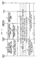
- Fig. 3 is a signal flow diagram showing the method of transmitting communication signals performed at the communication system 100 of Fig. 2.
- computer device 105 is described as a personal computer (PC)
- the computer interface circuit 150 is a standard computer modem
- the telephonic switch I 10 is a standard telephonic switch such as the SESS digital switch from Lucent Technologies, Inc.
- the communication network server 170 is an ISP
- the network 180 is the worldwide Internet
- the network server 120 is a computer system connected to the Internet
- the network site 125 is a web page
- the network site telephonic interface 175 is a standard modem
- the connection 145 is a standard telephonic network.
- step 185 the computer device 105 sends a signal to the telephonic switch 110 that instructs the telephonic switch 110 to establish a connection with the communication network server 170.
- step 190 the telephonic switch 110 sends a connection signal to the communication network server 170 to establish a connection with the network 180.
- the communication network server 170 in step 195, establishes a connection with the network 180.
- step 200 the communication network server 170 responds by sending a reply signal that the connection with the network 180 is established.
- step 205 the telephonic switch 110 informs the computer device 105 that a connection to the network 180 exists.
- the computer device 105 communicates with the network 180 and finds the network site 125.
- the computer device 105 communicates with the network site 125.
- the network site 125 sends a query signal to the computer device 105 which queries whether to initiate a point to point signal connection 145 between the network site 125 and the computer device 105.
- the computer device 105 responds to the query signal by requesting a point to point connection with the network site 125 by sending a response signal to the network site 125.
- the network site 125 in step 230. sends a data signal containing telephone identification data for the network site 125 to the computer device 105.
- the computer device 105 in step 235, then sends a control signal, via such interfaces as an application programming interface (API) or by using the telephony off hook flash followed by *signalling (e.g. *90) and the destination number. , to the telephonic switch 110 requesting a point to point connection with the network site 125.
- the telephonic switch 110 establishes a point to point connection with the network site 125.
- the computer device 105 and network site 125 communicate point to point.
- the point to point connection is a private circuit or switched-based connection that is routed from one site to another site across either "private facilities" which does not appear on shared public facilities or public networks.
- Illustrative of one form of the invention is a method for transmitting communication signals from the telephonic switch 110, via the communication network 115, to the network server 120 having the network site 125 for communication with the computer device 105 coupled with the telephonic switch 110.
- the steps of connecting the telephonic switch 110 to the network site 125 via the communication network 115. and establishing communication across the point to point path (signaling path 145) between the telephonic switch 110 and the network site 125 are performed.
- the step of establishing the point to point path 145 further includes the steps of creating, at the network site 125. the data signal containing the telephone identification number for the network site 125, and establishing a telephonic call from the telephonic switch 110 to the network site 125 using the data signal.
- the step of creating the data signal further includes the steps of creating a query signal at the network site 125, transmitting the query signal from the network site 125 to the computer device 105, creating a response signal at the computer device 105, and transmitting the response signal from the computer device 105 to the network site 125.
- the step of establishing the telephonic call further includes the steps of transmitting the data signal from the network site 125 to the computer device 105, transmitting a control signal, containing the telephone identification number of the network site 125, from the computer device 105 to the telephonic switch 110 and connecting the telephonic switch 110 to the network site 125 using the control signal.
- the computer device 105 and network site 125 may exchange secure information such as financial account data, credit card data. personal data, or voice two way communication.
- the computer device 105 possess software, similar to commonly available Internet telephone programs (some of which are embodiment in web browses produced by Netscape Communication, Inc. and Microsoft, Inc.), that allow the computer device 105 to simultaneously support a telephone connection with the network site 125. The difference is that these programs only allow the computer device 105 to connect the telephone call over the Internet.
- the system 100 of the present invention allows the telephone connection from the computer device 105 to the network site 125 to be via connection 145, Fig. 2. As such, the computer device 105 and network site 125 are connected simultaneously through the Internet, via the communication network 115, and the telephone network via a point to point telephone connection 145.
Landscapes
- Engineering & Computer Science (AREA)
- Computer Networks & Wireless Communication (AREA)
- Signal Processing (AREA)
- Telephonic Communication Services (AREA)
Abstract
Description
Claims (22)
- A method for transmitting communication signals from a telephonic switch, via a communication network, to a network server having a network site for communication with a computer device coupled with the telephonic switch comprising the steps of:connecting the telephonic switch to the network site via the communication network; andestablishing a point to point path between the telephonic switch and the network site.
- The method of claim I wherein the communication network is a shared public communication network.
- The method of claim 1 wherein the communication network is a worldwide Internet.
- The method of claim 1 wherein the network site is a web site.
- The method of claim 1 wherein the network site is a file transfer protocol site.
- The method of claim 1 wherein the point to point path is a standard telephonic communication path.
- The method of claim 6 wherein the standard telephonic communication path is a private circuit switched dialed calling path.
- The method of claim 1 wherein the point to point path is established in response to the establishment of a private switched based connection between the telephonic switch and the network site
- The method of claim 8 including the step of maintaining the connection between the telephonic switch and the network site via the communication site upon establishment of the private switched based connection between the telephonic switch and the network site.
- The method of claim 9 in which the communication network is a shared publically accessible communication network.
- The method of claim 10 wherein the shared publically accessible communication network is a worldwide Internet.
- The method of claim 11 wherein the step of establishing a point to point path includes the step of establishing a plurality of private switched based connections between the telephonic switch and the network site which avoid appearing on shared publically accessible communication networks.
- The method of claim 1 in which the step of establishing the point to point path further includes the steps of creating, at the network site, a data signal containing a telephone identification number for the network site, and
establishing a telephonic call from the telephonic switch to the network site using the data signal. - The method of claim 13 in which the step of creating the data signal further includes the steps of creating a query signal at the network site,transmitting the query signal from the network site to the computer device.creating a response signal at the computer device, andtransmitting the response signal from the computer device to the network site.
- The method of claim 13 in which the step of establishing the telephonic call further includes the steps of transmitting the data signal from the network site to the computer device;transmitting a control signal, containing telephone identification number of the network site, from the computer device to the telephonic switch, andconnecting the telephonic switch to the network site using the control signal.
- The method of claim 15 including the step of sending the control signal via an application programming interface.
- A communication system for transmitting communication signals from a telephonic switch to a network site on a network server comprising:a communication network connected in signal communication between the telephonic switch and the network server; anda point to point path connected between the telephonic switch and the network site.
- The system of claim 17 wherein the communication network is the Internet.
- The system of claim 17 wherein the network site is a web site
- The system of claim 17 wherein the network site is a file transfer protocol site.
- The system of claim 17 wherein the point to point path is a standard telephonic communication path.
- The system of claim 17 further including a network site telephonic interface which creates a query signal containing a telephone identification number for the network site and transmits the query signal to the computer device, and
a computer device interface circuit which creates a response signal in response to the query signal and transmits the response signal to network site.
Applications Claiming Priority (2)
| Application Number | Priority Date | Filing Date | Title |
|---|---|---|---|
| US24902799P | 1999-12-02 | 1999-12-02 | |
| US249027 | 1999-12-02 |
Publications (2)
| Publication Number | Publication Date |
|---|---|
| EP1119138A2 true EP1119138A2 (en) | 2001-07-25 |
| EP1119138A3 EP1119138A3 (en) | 2002-05-29 |
Family
ID=22941735
Family Applications (1)
| Application Number | Title | Priority Date | Filing Date |
|---|---|---|---|
| EP00301016A Withdrawn EP1119138A3 (en) | 1999-12-02 | 2000-02-09 | System and method for combining Internet connections with point-to-point telephonic connections |
Country Status (1)
| Country | Link |
|---|---|
| EP (1) | EP1119138A3 (en) |
Cited By (1)
| Publication number | Priority date | Publication date | Assignee | Title |
|---|---|---|---|---|
| US7342925B2 (en) | 2004-11-30 | 2008-03-11 | At&T Corp. | Technique for automated MAC address cloning |
Family Cites Families (1)
| Publication number | Priority date | Publication date | Assignee | Title |
|---|---|---|---|---|
| US6252869B1 (en) * | 1995-12-29 | 2001-06-26 | At&T Corp. | Data network security system and method |
-
2000
- 2000-02-09 EP EP00301016A patent/EP1119138A3/en not_active Withdrawn
Cited By (1)
| Publication number | Priority date | Publication date | Assignee | Title |
|---|---|---|---|---|
| US7342925B2 (en) | 2004-11-30 | 2008-03-11 | At&T Corp. | Technique for automated MAC address cloning |
Also Published As
| Publication number | Publication date |
|---|---|
| EP1119138A3 (en) | 2002-05-29 |
Similar Documents
| Publication | Publication Date | Title |
|---|---|---|
| US6738981B1 (en) | General access system | |
| JP3877782B2 (en) | Method and apparatus for secure data communication | |
| JP3357591B2 (en) | Communication device and communication path selection method | |
| US6167043A (en) | Method and system for small office and home office telephone private branch exchange allowing simultaneous data and voice communications | |
| US5781617A (en) | Communication server apparatus using frequency multiplexing and method | |
| US6738470B1 (en) | Distributed gateway system for telephone communications | |
| KR20010033293A (en) | Architecture independent application invocation over a telephony network | |
| JPH11136356A (en) | Call direction change system | |
| US8005112B2 (en) | Service connection method and architecture | |
| KR20100044203A (en) | Method, modem and server for bridging telephone calls into internet calls | |
| US6185225B1 (en) | Telecommunications equipment operable at two data rates | |
| AU760623B2 (en) | Local switch | |
| AU741103B2 (en) | A method and arrangement in communication networks for managing user related features through a user interface | |
| US6621859B1 (en) | Combined cable/DSL modem and method for high speed data communication | |
| US7130336B2 (en) | Apparatus and method for provision of a back-up connection in a telecommunication system | |
| US7065072B1 (en) | Method and system for providing telecommunication services by a plurality of service providers | |
| CA2298177A1 (en) | System and method for private switched based communication to a network site during network site communication through a communication network | |
| EP1190514B1 (en) | Broadband architecture using existing twisted pair | |
| WO1998026627A1 (en) | Enhanced services for atm switching using external control | |
| KR100247713B1 (en) | Method for control message format on voice message confirmation requirement in dpx | |
| JP4151291B2 (en) | Payment system, information processing apparatus and information processing method, recording medium, and program | |
| JP3517176B2 (en) | Connection method between telephone terminals | |
| KR100282059B1 (en) | IP Voice Terminal with Internet Fax | |
| WO2001093605A1 (en) | A method and system for managing communication traffic | |
| JPH118655A (en) | Communication system using OCN |
Legal Events
| Date | Code | Title | Description |
|---|---|---|---|
| PUAI | Public reference made under article 153(3) epc to a published international application that has entered the european phase |
Free format text: ORIGINAL CODE: 0009012 |
|
| AK | Designated contracting states |
Kind code of ref document: A2 Designated state(s): AT BE CH CY DE DK ES FI FR GB GR IE IT LI LU MC NL PT SE |
|
| AX | Request for extension of the european patent |
Free format text: AL;LT;LV;MK;RO;SI |
|
| PUAL | Search report despatched |
Free format text: ORIGINAL CODE: 0009013 |
|
| AK | Designated contracting states |
Kind code of ref document: A3 Designated state(s): AT BE CH CY DE DK ES FI FR GB GR IE IT LI LU MC NL PT SE |
|
| AX | Request for extension of the european patent |
Free format text: AL;LT;LV;MK;RO;SI |
|
| RIC1 | Information provided on ipc code assigned before grant |
Free format text: 7H 04L 12/28 A, 7H 04Q 3/00 B, 7H 04L 29/06 B |
|
| 17P | Request for examination filed |
Effective date: 20021116 |
|
| AKX | Designation fees paid |
Designated state(s): DE FR GB |
|
| 17Q | First examination report despatched |
Effective date: 20030224 |
|
| STAA | Information on the status of an ep patent application or granted ep patent |
Free format text: STATUS: THE APPLICATION IS DEEMED TO BE WITHDRAWN |
|
| 18D | Application deemed to be withdrawn |
Effective date: 20030909 |