EP1119075A2 - Electrical connection box - Google Patents
Electrical connection box Download PDFInfo
- Publication number
- EP1119075A2 EP1119075A2 EP01300326A EP01300326A EP1119075A2 EP 1119075 A2 EP1119075 A2 EP 1119075A2 EP 01300326 A EP01300326 A EP 01300326A EP 01300326 A EP01300326 A EP 01300326A EP 1119075 A2 EP1119075 A2 EP 1119075A2
- Authority
- EP
- European Patent Office
- Prior art keywords
- wiring substrate
- casing part
- casing
- electrical connection
- guide
- Prior art date
- Legal status (The legal status is an assumption and is not a legal conclusion. Google has not performed a legal analysis and makes no representation as to the accuracy of the status listed.)
- Granted
Links
Images




Classifications
-
- B—PERFORMING OPERATIONS; TRANSPORTING
- B60—VEHICLES IN GENERAL
- B60R—VEHICLES, VEHICLE FITTINGS, OR VEHICLE PARTS, NOT OTHERWISE PROVIDED FOR
- B60R16/00—Electric or fluid circuits specially adapted for vehicles and not otherwise provided for; Arrangement of elements of electric or fluid circuits specially adapted for vehicles and not otherwise provided for
- B60R16/02—Electric or fluid circuits specially adapted for vehicles and not otherwise provided for; Arrangement of elements of electric or fluid circuits specially adapted for vehicles and not otherwise provided for electric constitutive elements
- B60R16/023—Electric or fluid circuits specially adapted for vehicles and not otherwise provided for; Arrangement of elements of electric or fluid circuits specially adapted for vehicles and not otherwise provided for electric constitutive elements for transmission of signals between vehicle parts or subsystems
- B60R16/0238—Electrical distribution centers
-
- H—ELECTRICITY
- H01—ELECTRIC ELEMENTS
- H01R—ELECTRICALLY-CONDUCTIVE CONNECTIONS; STRUCTURAL ASSOCIATIONS OF A PLURALITY OF MUTUALLY-INSULATED ELECTRICAL CONNECTING ELEMENTS; COUPLING DEVICES; CURRENT COLLECTORS
- H01R13/00—Details of coupling devices of the kinds covered by groups H01R12/70 or H01R24/00 - H01R33/00
- H01R13/46—Bases; Cases
- H01R13/516—Means for holding or embracing insulating body, e.g. casing, hoods
- H01R13/518—Means for holding or embracing insulating body, e.g. casing, hoods for holding or embracing several coupling parts, e.g. frames
-
- H—ELECTRICITY
- H01—ELECTRIC ELEMENTS
- H01R—ELECTRICALLY-CONDUCTIVE CONNECTIONS; STRUCTURAL ASSOCIATIONS OF A PLURALITY OF MUTUALLY-INSULATED ELECTRICAL CONNECTING ELEMENTS; COUPLING DEVICES; CURRENT COLLECTORS
- H01R13/00—Details of coupling devices of the kinds covered by groups H01R12/70 or H01R24/00 - H01R33/00
- H01R13/62—Means for facilitating engagement or disengagement of coupling parts or for holding them in engagement
- H01R13/629—Additional means for facilitating engagement or disengagement of coupling parts, e.g. aligning or guiding means, levers, gas pressure electrical locking indicators, manufacturing tolerances
Definitions
- the invention relates to an electric connection box suitable to be mounted in, for example, a vehicle such as an automobile.
- the electric connection box aligns the casing parts by bringing the wiring substrate casing part in contact with guide pieces formed on the upper face of the laminate casing part.
- bus bars are aligned with the substrate connector indirectly by positioning of the wiring substrate through its casing part. Therefore, there have been problems that the deviation of the connection position of the bus bars with the connector occurs, and good connection cannot be achieved because of dimension tolerance of the respective casing parts, assembly error of the wiring substrate in its casing part, and the like.
- the object of the invention is to provide an electric connection box capable of satisfactorily connecting the bus bar laminate with a connector.
- an electrical connection box comprising a first casing part and a second casing part connectable with the first casing part.
- a bus bar laminate having at least one bus bar and at least one insulation layer laminated together, is mounted in the first casing part and has projecting terminals.
- a wiring substrate is mounted in the second casing part and has connectors carried on it adapted to engage and make connection to the projecting terminals of the bus bar laminate when the casing parts are connected.
- the first casing part and the wiring substrate have portions constituting mutually engageable guide conformations which, during connection of the casing parts, directly establish mutual alignment of the first casing part and the wiring substrate before the connectors engage the projecting terminals.
- the wiring substrate is directly positioned against the laminate casing part by the positioning procedure performed by the guide conformations.
- the positioning is carried out before the tab terminals of the bus bars are inserted in the connectors of the wiring substrate. Accordingly, it is assured that the connection position of the bus bars coincides with the connectors without being influenced by dimensional tolerance and the like of the first casing part. Therefore, good connection between the bus bars and the connectors can be achieved.
- the first casing part has a portion overlying the bus bar laminate and directly engaging the projecting terminals so as to determine the position of the projecting terminals relative to said first casing part.
- the wiring substrate is a planar board carrying wiring and a plurality of electrical components.
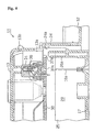
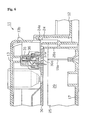
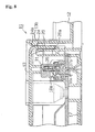
- the box 11 typically arranged the interior space of an automobile, has a first casing part for housing a bus bar laminate, here called laminate case 12, made by molding of a suitable synthetic resin, and a second casing part for housing a wiring substrate, here called substrate case 13, also made by molding of suitable synthetic resin and detachably mounted on the upper face of the laminate case 12.
- the laminate case 12 is composed of a lower case part 16 and an upper case part 17 which are detachably joined. An upper opening of the lower case part 16 is occupied by the upper case part 17.
- a bus bar laminate 20 obtained by alternatively laminating bus bars 18 made of a metal and insulation plates 19 made of a synthetic resin is accommodated.
- the bus terminals 18a formed on the bus bars 18 penetrate the upper case part 17 and protrude outward from the inside of the laminate case 12.
- Structures 21 for receiving exterior connectors protrude at the lower face of the lower case part 16.
- the laminate 20 is supported on the inside end faces of the respective structures 21.
- Guide walls 24 stand up on the upper face of the upper case part 17, and assist in positioning the substrate case 13, when the laminate case 12 and substrate case 13 are joined. Hooking claws 24a are formed on the upper inside faces of the guide walls 24. A recess 29 to receive the wiring substrate is defined on the upper face of the upper case part 17 inside the guide walls 24 by the approximately rectangular plan wall 25.
- Two guide projections 26a,26b are integrally formed (molded) with the wall 25 at opposite sides of the case 12 and project slightly higher than the upper end of the wall 25.
- the projecting guide parts 26a,26b oppose each other and are hollow inside to prevent the occurrence of mold sink on their surfaces in molding.
- connection structures 28 for a wire harness having terminals 27 inside are integrally formed on the upper part of the case.
- the wiring substrate 30 is a planar board having electrical wiring on its surface and carrying electrical components is installed and fixed by screws 33 on the substrate case 13, and nearly completely blocks the lower opening 13a. Through apertures 35 in the substrate 30, screws 34 are inserted into the fixing parts 22 of the laminate case 12 fixing the laminate 12 and the substrate 13 together. Hooking projections 13b are formed at places corresponding to the hooking claws 24a, on the outside face of the substrate case 13.
- connectors 31 are carried on the wiring substrate 30. One is shown in FIG. 2. Connecting terminals 36 connected to the wiring substrate 30 are provided in the connector 31. The tab terminals 18a make connection with the connecting terminals 36 through the holes 30a in the wiring substrate 30, when the cases 12,13 are joined.
- the assembly of the electrical connection box 11 is as follows:-
- the upper opening of the lower case 16 is confronted with the lower opening 13a of the substrate case 13.
- the laminate case 12 is approached to the substrate case 13.
- the rim part of the substrate case 13 is brought in contact with the inside face of the guide walls 24, and the position of the respective notches 37a,37b formed on the wiring substrate 30 is matched with the position of the guide projections 26a,26b provided at the edge of the recess 29.
- the respective notches 37a,37b engage with the respective guide projections 26a,26b.
- the wiring substrate 30 is thus directly aligned to the laminate case 12.
- the correct position of the tab terminals 18a of the bus bars 18 with the connecting terminals 36 of the connector 31 is achieved.
- the substrate 30 and the case 12 are aligned before the tab terminals 18a enter the apertures 30a.
- the wiring substrate 30 is received in the recess 29 while the notches 37a,37b slide along the two guide projections 26a,26b.
- the tab terminals 18a of the bus bars 18 are inserted in the connectors 31 through the insertion holes 30a.
- the hooking claws 24a provided on the guide walls 24 are hooked on the hooking projections 13b of the case 13, to lock the cases 12,13 together.
- the screws 34 are passed through holes 35, and engaged with the threaded parts 27.
- the guide projections 26a,26b were provided on the case 12, and the notches 37a,37b on the wiring substrate 30.
- This relation may be inverted. Namely, the notches may be on the case 12, and the guide projections on the wiring substrate 30.
- the positioning of the wiring substrate 30 against the case 12 was carried out by concave and convex parts.
- this positioning may be achieved by holes in the wiring substrate 30, and protrusions on the bottom face of the recess 29 engaging these holes.
Landscapes
- Engineering & Computer Science (AREA)
- Mechanical Engineering (AREA)
- Connection Or Junction Boxes (AREA)
- Insertion, Bundling And Securing Of Wires For Electric Apparatuses (AREA)
- Multi-Conductor Connections (AREA)
Abstract
Description
Claims (8)
- An electrical connection box comprising connectable first and second casing parts (12,13), a bus bar laminate (20) having at least one bus bar and at least one insulation layer laminated together mounted in said first casing part and having projecting terminals (18a), a wiring substrate (30) mounted in said second casing part, and connectors (31) carried on said wiring substrate adapted to engage and make connection to said projecting terminals (18a) of said bus bar laminate when said first and second casing parts are connected,
characterised in that at least one portion of said first casing part (12) and at least one portion of said wiring substrate (30) constitute respectively mutually engageable guide conformations (26a,26b,37a,37b) which, during connection of said first and second casing parts, directly establish mutual alignment of said first casing part and said wiring substrate before said connectors (31) engage said projecting terminals (18a). - An electrical connection box according to claim 1 wherein said mutually engageable guide conformations comprise at least one guide projection (26a,26b) on one of said first casing part and said wiring substrate and at least one guide recess (37a,37b) in the other thereof.
- An electrical connection box according to claim 2 wherein said first casing part (12) has a substrate-receiving recess (29) bounded by a surrounding wall (25) which receives said wiring substrate (30) when said first and second casing parts are connected together, said guide projection (26a,26b) being a protrusion on said surrounding wall (25) projecting inwardly to said substrate-receiving recess, and said guide recess being a notch (37A,37B) in a peripheral region of said wiring substrate.
- An electrical connection box according to claim 3, wherein said guide projection is in one-piece with said surrounding wall (25).
- An electrical connection box according to any one of claims 1 to 4, wherein said first casing part (12) has a portion (17) overlying said bus bar laminate and directly engaging said projecting terminals (18a) so as to determine the position of said projecting terminals relative to said first casing part.
- An electrical connection box according to any one of claims 1 to 5, wherein said projecting terminals (18a) of said bus bar laminate and said guide conformation (26a,26b) of said first casing part (12) are upstanding towards said second casing part (13) in the direction of mutual approach of said first and second casing parts (12,13) during connection thereof, said guide conformation (26a,26b) of said first casing part standing up higher than said projecting terminals so as to engage said wiring substrate before said projecting terminals during the connection of the casing parts.
- An electrical connection box according to any one of claims 1 to 6, wherein each of said first casing part (12) and said wiring substrate (30) has a pair of said portions (26a,26b,37a,37b) constituting mutually engageable guide conformations, located respectively at opposite sides of the electrical connection box.
- An electrical connection box according to any one of claims 1 to 7, wherein said wiring substrate is a planar board carrying wiring and a plurality of electrical components.
Applications Claiming Priority (2)
| Application Number | Priority Date | Filing Date | Title |
|---|---|---|---|
| JP2000011743A JP3543713B2 (en) | 2000-01-20 | 2000-01-20 | Electrical junction box |
| JP2000011743 | 2000-01-20 |
Publications (3)
| Publication Number | Publication Date |
|---|---|
| EP1119075A2 true EP1119075A2 (en) | 2001-07-25 |
| EP1119075A3 EP1119075A3 (en) | 2002-12-18 |
| EP1119075B1 EP1119075B1 (en) | 2005-07-20 |
Family
ID=18539568
Family Applications (1)
| Application Number | Title | Priority Date | Filing Date |
|---|---|---|---|
| EP01300326A Expired - Lifetime EP1119075B1 (en) | 2000-01-20 | 2001-01-16 | Electrical connection box |
Country Status (4)
| Country | Link |
|---|---|
| US (1) | US6430055B2 (en) |
| EP (1) | EP1119075B1 (en) |
| JP (1) | JP3543713B2 (en) |
| DE (1) | DE60111963T2 (en) |
Cited By (1)
| Publication number | Priority date | Publication date | Assignee | Title |
|---|---|---|---|---|
| EP1548883A1 (en) * | 2003-12-22 | 2005-06-29 | Yazaki Corporation | Electric connection box and bus bar-mounting structure thereof |
Families Citing this family (12)
| Publication number | Priority date | Publication date | Assignee | Title |
|---|---|---|---|---|
| EP1586488A1 (en) * | 2000-10-26 | 2005-10-19 | Sumitomo Wiring Systems, Ltd. | Electrical junction box for a vehicle |
| US6717051B2 (en) * | 2001-02-21 | 2004-04-06 | Denso Corporation | Electronic control unit for use in automotive vehicle |
| US6679708B1 (en) * | 2002-09-10 | 2004-01-20 | Sumitomo Wiring Systems, Ltd. | Vehicle junction box having power distribution center with terminal for jump-starting vehicle |
| JP2004328939A (en) * | 2003-04-25 | 2004-11-18 | Sumitomo Wiring Syst Ltd | Electrical junction box |
| US7134905B1 (en) | 2005-03-31 | 2006-11-14 | Yazaki North America, Inc. | Connection system with electronic circuit board |
| JP5200857B2 (en) * | 2008-10-28 | 2013-06-05 | 住友電装株式会社 | Electrical junction box |
| JP5055255B2 (en) * | 2008-12-19 | 2012-10-24 | 株式会社藤商事 | Game machine |
| US8441800B2 (en) * | 2009-03-26 | 2013-05-14 | Panasonic Corporation | Vehicle-mounted electronic device |
| JP5445009B2 (en) * | 2009-10-08 | 2014-03-19 | 富士通株式会社 | Electronics |
| CN105453712B (en) * | 2013-08-13 | 2017-03-29 | 三菱电机株式会社 | Electronic equipment |
| JP6404258B2 (en) * | 2016-04-26 | 2018-10-10 | 矢崎総業株式会社 | Electrical junction box and wire harness |
| JP7314190B2 (en) * | 2021-03-18 | 2023-07-25 | 矢崎総業株式会社 | electric junction box |
Family Cites Families (7)
| Publication number | Priority date | Publication date | Assignee | Title |
|---|---|---|---|---|
| CH656041A5 (en) * | 1982-06-23 | 1986-05-30 | Elektrowatt Ag | APPARATUS MOUNTED ON A COMMON RAIL. |
| JPH0614475B2 (en) * | 1989-06-09 | 1994-02-23 | 矢崎総業株式会社 | Connection structure of bus bar and insulation displacement terminal for branch in electric junction box |
| DE69529867T2 (en) * | 1994-07-15 | 2003-12-24 | Sumitomo Wiring Systems, Ltd. | Electrical junction box |
| US5822189A (en) * | 1995-12-14 | 1998-10-13 | Sumitomo Wiring Systems, Ltd. | Electrical connection box, a connection construction, a busbar fixing construction and a connection terminal |
| US5764487A (en) * | 1996-08-06 | 1998-06-09 | Yazaki Corporation | Junction block with integral printed circuit board and electrical connector for same |
| JP3405249B2 (en) * | 1999-02-01 | 2003-05-12 | 住友電装株式会社 | Electrical junction box |
| JP3808665B2 (en) * | 1999-07-01 | 2006-08-16 | 住友電装株式会社 | Electrical junction box |
-
2000
- 2000-01-20 JP JP2000011743A patent/JP3543713B2/en not_active Expired - Fee Related
-
2001
- 2001-01-16 DE DE60111963T patent/DE60111963T2/en not_active Expired - Lifetime
- 2001-01-16 EP EP01300326A patent/EP1119075B1/en not_active Expired - Lifetime
- 2001-01-19 US US09/764,437 patent/US6430055B2/en not_active Expired - Fee Related
Cited By (1)
| Publication number | Priority date | Publication date | Assignee | Title |
|---|---|---|---|---|
| EP1548883A1 (en) * | 2003-12-22 | 2005-06-29 | Yazaki Corporation | Electric connection box and bus bar-mounting structure thereof |
Also Published As
| Publication number | Publication date |
|---|---|
| DE60111963T2 (en) | 2006-05-24 |
| US20010009506A1 (en) | 2001-07-26 |
| JP3543713B2 (en) | 2004-07-21 |
| JP2001211527A (en) | 2001-08-03 |
| EP1119075A3 (en) | 2002-12-18 |
| EP1119075B1 (en) | 2005-07-20 |
| US6430055B2 (en) | 2002-08-06 |
| DE60111963D1 (en) | 2005-08-25 |
Similar Documents
| Publication | Publication Date | Title |
|---|---|---|
| US8002569B2 (en) | Electric connection box | |
| US8070534B2 (en) | Electric connection block | |
| EP1119075B1 (en) | Electrical connection box | |
| EP0782216B1 (en) | An electrical connection box, a connection construction, a bus bar fixing construction and a connection terminal | |
| US6496096B2 (en) | Fuse assembly | |
| JPH08185921A (en) | Electrical junction box | |
| US10247757B2 (en) | Electricity meter forms module | |
| US7771212B2 (en) | Electrical junction box | |
| US6540543B1 (en) | Electrical connection box | |
| US20040048520A1 (en) | Junction box | |
| JP2008117675A (en) | Method for forming printed circuit board with connector, and electric junction box for automobile provided with printed circuit board | |
| US6217377B1 (en) | Electric circuit connection container | |
| JP5488364B2 (en) | Electrical junction box assembly unit | |
| JP4152306B2 (en) | Electronic unit | |
| JP2001006792A (en) | Electric junction box and method of assembling the same | |
| JP2002305829A (en) | Fixing structure of electrical junction box and connector housing | |
| JP2001286030A (en) | Electrical junction box | |
| US6890209B2 (en) | Pressure welding terminal for plate connector | |
| JP2002064920A (en) | Junction box | |
| JP3139357B2 (en) | Busbar fixing structure in electrical junction box with electronic circuit | |
| JP3042391B2 (en) | Electrical connection box with electronic circuit | |
| JP2993416B2 (en) | Electrical connection box with electronic circuit | |
| JP2002058129A (en) | Electrical junction box and wiring board | |
| JP3685061B2 (en) | Junction box | |
| CN115693318A (en) | Connector with a locking member |
Legal Events
| Date | Code | Title | Description |
|---|---|---|---|
| PUAI | Public reference made under article 153(3) epc to a published international application that has entered the european phase |
Free format text: ORIGINAL CODE: 0009012 |
|
| 17P | Request for examination filed |
Effective date: 20010205 |
|
| AK | Designated contracting states |
Kind code of ref document: A2 Designated state(s): AT BE CH CY DE DK ES FI FR GB GR IE IT LI LU MC NL PT SE TR |
|
| AX | Request for extension of the european patent |
Free format text: AL;LT;LV;MK;RO;SI |
|
| PUAL | Search report despatched |
Free format text: ORIGINAL CODE: 0009013 |
|
| AK | Designated contracting states |
Kind code of ref document: A3 Designated state(s): AT BE CH CY DE DK ES FI FR GB GR IE IT LI LU MC NL PT SE TR |
|
| AX | Request for extension of the european patent |
Free format text: AL;LT;LV;MK;RO;SI |
|
| 17Q | First examination report despatched |
Effective date: 20030723 |
|
| AKX | Designation fees paid |
Designated state(s): DE FR GB |
|
| GRAP | Despatch of communication of intention to grant a patent |
Free format text: ORIGINAL CODE: EPIDOSNIGR1 |
|
| GRAS | Grant fee paid |
Free format text: ORIGINAL CODE: EPIDOSNIGR3 |
|
| RBV | Designated contracting states (corrected) |
Designated state(s): DE GB |
|
| GRAA | (expected) grant |
Free format text: ORIGINAL CODE: 0009210 |
|
| AK | Designated contracting states |
Kind code of ref document: B1 Designated state(s): DE GB |
|
| RBV | Designated contracting states (corrected) |
Designated state(s): DE GB |
|
| REG | Reference to a national code |
Ref country code: GB Ref legal event code: FG4D |
|
| REF | Corresponds to: |
Ref document number: 60111963 Country of ref document: DE Date of ref document: 20050825 Kind code of ref document: P |
|
| PLBE | No opposition filed within time limit |
Free format text: ORIGINAL CODE: 0009261 |
|
| STAA | Information on the status of an ep patent application or granted ep patent |
Free format text: STATUS: NO OPPOSITION FILED WITHIN TIME LIMIT |
|
| 26N | No opposition filed |
Effective date: 20060421 |
|
| PGFP | Annual fee paid to national office [announced via postgrant information from national office to epo] |
Ref country code: GB Payment date: 20130116 Year of fee payment: 13 Ref country code: DE Payment date: 20130109 Year of fee payment: 13 |
|
| REG | Reference to a national code |
Ref country code: DE Ref legal event code: R119 Ref document number: 60111963 Country of ref document: DE |
|
| GBPC | Gb: european patent ceased through non-payment of renewal fee |
Effective date: 20140116 |
|
| REG | Reference to a national code |
Ref country code: DE Ref legal event code: R119 Ref document number: 60111963 Country of ref document: DE Effective date: 20140801 |
|
| PG25 | Lapsed in a contracting state [announced via postgrant information from national office to epo] |
Ref country code: DE Free format text: LAPSE BECAUSE OF NON-PAYMENT OF DUE FEES Effective date: 20140801 |
|
| PG25 | Lapsed in a contracting state [announced via postgrant information from national office to epo] |
Ref country code: GB Free format text: LAPSE BECAUSE OF NON-PAYMENT OF DUE FEES Effective date: 20140116 |