The present invention relates generally to an optical device used in
a communication system in which optical fibers are utilized. More
particularly, the present invention relates to an optical device having rod
lenses.
Recently, due to the explosive growth of the internet, there is a
strong demand for increase in capacity of an optical fiber communications
network. For the purpose of increasing the capacity, the development of
WDM (Wavelength Division Multiplexing) communication has been
accelerated. In the WDM communication, since lights with slightly
different wavelengths convey individual pieces of information, an optical
function element such as a filter, an isolator, or the like with excellent
wavelength selectivity is required in an optical device.
The optical device often has a configuration such that light leaving
an end face of an optical fiber from which light outgoes (hereinafter referred
to as an "output fiber" throughout the present specification) is changed to a
parallel beam by a collimator, and the parallel beam then is allowed to pass
through a flat plate component with a filter or isolator function and is
condensed by a condenser lens again to enter an end face of an optical fiber
from which light enters (hereinafter referred to as an "input fiber"
throughout the present specification). A rod lens with a refractive index
distribution in its radial direction, a glass ball lens, a pressed aspherical lens,
or the like is used as the collimator or the condenser lens. In view of the
shape and aberration correction, the rod lens can be used most easily.
FIG. 1 is a schematic view showing an optical system of an optical
device having rod lenses. Generally, as shown in FIG. 1, end faces (facing
rod lenses) of an output fiber 1 and an input fiber 2 are processed to have
slopes with a tilt angle of 6° to 8° to prevent crosstalk caused by reflected
light (the tilt angle of the end face of the output fiber 1 is indicated as FA ,
and that of the end face of the input fiber 2 as FB ). For the same reason, the
end faces (facing the optical fibers) of a first rod lens 3 and a second rod lens
4 also are processed to have slopes (the tilt angle of the end face of the first
rod lens 3 is indicated as PA , and that of the end face of the second rod lens 4
as PB ). The output fiber 1 and the first rod lens 3 are positioned to oppose
each other with a suitable air space WA being provided therebetween, and
the second rod lens 4 and the input fiber 2 are positioned to oppose each
other with a suitable air space WB being provided therebetween. In order to
reduce the loss due to reflected light, the spaces between the output fiber 1
and the first rod lens 3 and between the second rod lens 4 and the input fiber
2 may be filled with a transparent liquid or solid with a refractive index close
to that of the optical fibers and the rod lenses in some cases. An optical
function element such as a filter, an isolator, or the like is placed between the
rod lenses 3 and 4 (i.e. in a space L).
Generally, a single-mode fiber is used as an optical fiber for
communication, and therefore a beam leaving the fiber is a Gaussian beam.
In the present specification, the light ray with a highest intensity at the
symmetrical center of the Gaussian beam is referred to as a "center light ray".
In order to increase the coupling efficiency between the optical fibers 1 and 2
shown in FIG. 1, the respective optical fibers 1 and 2 and rod lenses 3 and 4
are required to be positioned so that the following conditions (1) to (3) are
satisfied.
| | Ref. Ex. 1 | Ref. Ex. 2 |
| Outgoing-Side Fiber End Face Tilt FA | 8.00° | 8.00° |
| Outgoing-Side Space WA | 0.2351 mm | 0.2351 mm |
| Outgoing-Side Rod Lens End Face Tilt QA | 8.00° | 8.00° |
| Outgoing-Side Rod Lens Length ZA | 4.4329 mm | 4.4329 mm |
| Lens Interval L | 2.00 mm | 2.00 mm |
| Incident-Side Rod Lens Length ZB | 4.4329 mm | 4.4329 mm |
| Incident-Side Rod Lens End Face Tilt QB | 8.00° | 8.00° |
| Incident-Side Space WB | 0.2340 mm | 0.2340 mm |
| Incident-Side Fiber End Face Tilt FB | 8.00° | 8.00° |
| QA0 | 4.55° | 4.55° |
| QB0 | 4.55° | 4.55° |
| (QA + QB) - (QA0 + QB0) | -9.11° | -9.11° |
| 3A | 0.43° | 0.43° |
| 3B | 0.43° | 0.43° |
| 3A - 3B | 0.00° | 0.00° |
| Shift between Center Light Ray and Optical Axis ▵Y | 0.00005 mm | 0.00005 mm |
| Tilt of Center Light Ray with respect to Optical Axis TLA | -2.850° | By the tilting of the fibers, the tilt is set to be 0°. |
| Coupling Efficiency | 0.7730 (-1.118dB) | 0.9828 (-0.0753dB) |
| Ref. Ex. = Reference Example |
The same correction also can be made by the tilting or shifting of the
output fiber 1 and the respective rod lenses 3 and 4, individually.
However, it takes time to correct the positions (in the X and Y
directions) and the tilt angles of the optical fibers and the rod lenses, which
causes cost increase.
Therefore, in view of the assembly of an optical device, for instance,
as shown in FIG. 2, it is desirable to hold the output fiber 1 and the input
fiber 2 with ferrules 5 with the same outer diameter as those of the first and
second rod lenses 3 and 4 and to insert the input fiber 2, the second rod lens
4, the first rod lens 3, and the output fiber 1 into a single sleeve 6,
sequentially. In this case, it is not possible to carry out the "position shift"
and "tilt angle correction", but it is possible to adjust the positions of the
respective optical fibers 1 and 2 by pulling and inserting them in a Z axis
direction. In FIG. 2, numeral 8 indicates an optical function element.
In order to obtain high coupling efficiency in the configuration
shown in FIG. 2, an optical system is required, which is designed so that the
above-mentioned conditions are satisfied through the adjustment of the
respective optical fibers 1 and 2 in the Z axis direction alone.
With such a current situation in mind, the present invention is
intended to provide an optical device including optical fibers and rod lenses
with all their optical axes being allowed to coincide, particularly, through
optimization of the angles of faces of the rod lenses processed to have slopes,
wherein the path of a center light ray entering an input fiber is allowed to
coincide with the optical axes.
In order to achieve the above-mentioned object, an optical device
with a first configuration according to the present invention includes an
output fiber, a first rod lens, a second rod lens, an input fiber, and an optical
function element. The first rod lens converts a beam leaving an end face of
the output fiber into a substantially parallel light ray, and after passing
through the optical function element, the substantially parallel light ray is
condensed by the second rod lens and then enters the input fiber. Optical
axes of the output fiber, the first rod lens, the second rod lens, and the input
fiber all coincide. The refractive index distribution of the first rod lens is
expressed by
Eq. 1 nA(r)2 = n0A 2 · {1 - (gA • r)2 + h4A (gA • r)4
+ h6A (gA • r)6 + h8A (gA · r)8 +•••},
wherein r denotes a radial distance from the optical axis of the first rod lens,
n0A a refractive index on the optical axis of the first rod lens, and gA , h4A , h6A ,
and h8A refractive index distribution coefficients. The refractive index
distribution of the second rod lens is expressed by
Eq. 2 nB(r)2 = n0B 2 • {1- (gB • r)2 + h4B (gB • r)4 + h6B(gB • r)6 + h8B (gB • r)8 + •••},
wherein r denotes a radial distance from the optical axis of the second rod
lens, n0B a refractive index on the optical axis of the second rod lens, and gB,
h4B, h6B , and h8B refractive index distribution coefficients. A relationship of
Eq. 3 FA • FB > 0
is satisfied, wherein FA indicates an angle between a line normal to a face,
from which light outgoes, (hereinafter referred to as "an outgoing face") of
the output fiber and an optical axis of the optical device as a whole and FB
denotes an angle between a line normal to a face, from which light enters,
(hereinafter referred to as "an incident face") of the input fiber and the
optical axis of the optical device as a whole. When 3A and 3B are defined by
Eq. 4 3A = n0A • gA • WA • (nFA - nLA) FA / (nM • nLA) + (nM - n0A) • QA / nM
and
Eq. 5 3B = n0B • gB • WB • (nFB - nLB) FB / (nM • nLB) + (nM - n0B) • QB / nM,
wherein nFA indicates a core-center refractive index of the output fiber, nFB a
core-center refractive index of the input fiber, WA an interval between the
output fiber and the first rod lens, WB an interval between the second rod
lens and the input fiber, nLA a refractive index of a medium between the
output fiber and the first rod lens, nLB a refractive index of a medium
between the second rod lens and the input fiber, nM a refractive index of a
medium between the first rod lens and the second rod lens, QA an angle
between a line normal to an outgoing face of the first rod lens and the optical
axis of the optical device as a whole, and QB an angle between a line normal
to an incident face of the second rod lens and the optical axis of the optical
device as a whole, 3A and 3B satisfy
Eq. 6 0 ≤ | 3A - 3B | ≤ π / 180
and relationships of
Eq. 7 0 ≤ |PA | ≤ 15 • (π / 180)
and
Eq. 8 0 ≤ |PB | ≤ 15 • (π / 180)
are satisfied, wherein PA denotes an angle between a line normal to an
incident face of the first rod lens and the optical axis of the optical device as a
whole, and PB an angle between a line normal to an outgoing face of the
second rod lens and the optical axis of the optical device as a whole.
According to the optical device with the first configuration, the path
of a center light ray entering the input fiber is allowed to coincide with the
optical axis of the whole in the configuration in which the angles of the faces
of the first and second rod lenses processed to have slopes are optimized and
thus the optical axes of the output fiber, the first rod lens, the second rod lens,
and the input fiber all coincide. As a result, the assembly and adjustment of
the optical device can be simplified considerably, and thus the production
cost can be reduced.
An optical device with a second configuration of the present
invention includes an output fiber, a first rod lens, a second rod lens, an
input fiber, and an optical function element. The first rod lens converts a
beam leaving an end face of an output fiber into a substantially parallel light
ray, and after passing through the optical function element, the substantially
parallel light ray is condensed by the second rod lens and then enters the
input fiber. Optical axes of the output fiber, the first rod lens, the second
rod lens, and the input fiber all coincide. The refractive index distribution
of the first rod lens is expressed by
Eq. 9 nA(r)2 = n0A 2 • {1 - (gA • r)2 + h4A (gA • r)4 + h6A (gA • r)6 + h8A (gA • r)8 + •••},
wherein r denotes a radial distance from the optical axis of the first rod lens,
n0A a refractive index on the optical axis of the first rod lens, and gA , h4A , h6A ,
and h8A refractive index distribution coefficients. The refractive index
distribution of the second rod lens is expressed by
Eq. 10 nB(r)2 = n0B 2 • {1 - (gB • r)2 + h4B (gB • r)4 + h6B (gB • r)6 + h8B (gB • r)8 + •••},
wherein r denotes a radial distance from the optical axis of the second rod
lens, n0B a refractive index on the optical axis of the second rod lens, and gB ,
h4B , h6B , and h8B refractive index distribution coefficients. A relationship of
Eq. 11 FA • FB < 0
is satisfied, wherein FA indicates an angle between a line normal to an
outgoing face of the output fiber and an optical axis of the optical device as a
whole and FB denotes an angle between a line normal to an incident face of
the input fiber and the optical axis of the optical device as a whole. When
QA0 and QB0 are defined by
Eq. 12 QA0 = n0A • gA • WA • (n0A - nLA) • PA /{nLA • (n0A-nM)}
and
Eq. 13 QB0 = n0B • gB • WB • (n0B-nLB) • PB / {nLB • (n0B - nM)},
wherein if n0A - nM = 0, QA0 = 0, and if n0B - nM = 0, QB0 = 0, and nFA indicates
a core-center refractive index of the output fiber, nFB a core-center refractive
index of the input fiber, WA an interval between the output fiber and the first
rod lens, WB an interval between the second rod lens and the input fiber, nLA
a refractive index of a medium between the output fiber and the first rod lens,
nLB a refractive index of a medium between the second rod lens and the input
fiber, nM a refractive index of a medium between the first rod lens and the
second rod lens, PA an angle between a line normal to an incident face of the
first rod lens and the optical axis of the optical device as a whole, and PB an
angle between a line normal to an outgoing face of the second rod lens and
the optical axis of the optical device as a whole, relationships of
Eq. 14 - (π / 180) ≤ QA - QA0 ≤ (π / 180)
and
Eq. 15 - (π / 180) ≤ QB - QB0 ≤ (π / 180)
are satisfied, wherein QA denotes an angle between a line normal to an
outgoing face of the first rod lens and the optical axis of the optical device as
a whole, and QB indicates an angle between a line normal to an incident face
of the second rod lens and the optical axis of the optical device as a whole,
and
PA and PB satisfy
Eq. 16 0 ≤ | PA | ≤ 15 • (π / 180)
and
Eq. 17 0 ≤ | PB | ≤ 15 • (π / 180).
According to the optical device with the second configuration, the
path of a center light ray entering the input fiber is allowed to coincide with
the optical axis of the whole in the configuration in which the angles of the
faces of the first and second rod lenses processed to have slopes are optimized
and thus the optical axes of the output fiber, the first rod lens, the second rod
lens, and the input fiber all coincide. As a result, the assembly and
adjustment of the optical device can be simplified considerably, and thus the
production cost can be reduced.
In the optical device with the first configuration of the present
invention, it is preferable that when QA0 and QB0 are defined by
Eq. 18 QA0 = {(0.5 • n0A 2 • gA 2 • L • WA - nLA • nM) • (nFA - nLA) FA + nLA • nM (n0A - nLA) • PA} / {0.5 • n0A • nLA • gA • L • (n0A - nM)}
in the case of L > 0 and
QA0 = 0 in the case of L = 0, and
Eq. 19 QB0 = {(0.5 • n0B 2 • gB 2 • L • WB - nLB • nM) •
(nFB - nLB) FB + nLB • nM (n0B - nLB) • PB} / {0.5 • n0B • nLB • gB • L • (n0B - nM)}
in the case of L > 0 and
QB0 = 0 in the case of L = 0,
wherein L denotes an interval between the first rod lens and the second rod
lens on the optical axis of the optical device as a whole, a relationship of
Eq. 20 -2.5 • (π / 180) ≤ (QA + QB) - (QA0 + QB0) ≤ + 2 5 • (π / 180)
is satisfied, wherein QA denotes an angle between a line normal to an
outgoing face of the first rod lens and the optical axis of the optical device as
a whole, and QB indicates an angle between a line normal to an incident face
of the second rod lens and the optical axis of the optical device as a whole.
In the optical devices with the first and second configurations of the
present invention, it is preferable that a path of a light ray at a symmetrical
center of light intensity distribution of a beam leaving the output fiber
coincides with the optical axis of the optical device as a whole after the light
ray enters the input fiber.
In the optical devices with the first and second configurations of the
present invention, it is preferable that a relationship of 1.4 ≤ n0A ≤ 2.0 is
satisfied.
In the optical devices with the first and second configurations of the
present invention, it is preferable that a relationship of 1.4 ≤ n0B ≤ 2.0 is
satisfied.
In the optical devices with the first and second configurations of the
present invention, it is preferable that a relationship of 0.125 mm ≤ 2 r0A ≤ 5
mm is satisfied, wherein r0A indicates a radius of the first rod lens.
In the optical devices with the first and second configurations of the
present invention, it is preferable that a relationship of 0.125 mm ≤ 2 r0B ≤ 5
mm is satisfied, wherein r0B indicates a radius of the second rod lens.
In the optical devices with the first and second configurations of the
present invention, it is preferable that a relationship of 0.1 ≤ n0A · gA · r0A ≤ 1
is satisfied.
In the optical devices with the first and second configurations of the
present invention, it is preferable that a relationship of 0.1 ≤ n0B · gB · r0B ≤ 1
is satisfied.
In the optical devices with the first and second configurations of the
present invention, it is preferable that a relationship of 4 · (π / 180) ≤ |FA | ≤
15 · (π / 180) is satisfied, and further preferably, a relationship of 6 · (π / 180)
≤ |FA | ≤ 8 · (π / 180) is satisfied.
In the optical devices with the first and second configurations of the
present invention, it is preferable that a relationship of 4 · (π / 180) ≤ | FB | ≤
15 · (π / 180) is satisfied, and further preferably, a relationship of 6 · (π / 180)
≤ |FB | ≤ 8 · (π / 180) is satisfied.
In the optical devices with the first and second configurations of the
present invention, it is preferable that a relationship of gA · WA ≤ 0.2 is
satisfied.
In the optical devices with the first and second configurations of the
present invention, it is preferable that a relationship of gB · WB ≤ 0.2 is
satisfied.
In the optical devices with the first and second configurations of the
present invention, it is preferable that a relationship of | FA | = |FB | is
satisfied.
In the optical devices with the first and second configurations of the
present invention, it is preferable that a relationship of nLA = nLB is satisfied,
and further preferably, a relationship of nLA = nLB = 1 is satisfied.
In the optical devices with the first and second configurations of the
present invention, it is preferable that relationships of n0A = n0B , gA = gB, and
r0A = r0B are satisfied.
In the optical device with the first configuration of the present
invention, it is preferable that a relationship of PA = PB is satisfied.
In the optical device with the second configuration of the present
invention, it is preferable that a relationship of PA = - PB is satisfied.
In the optical devices with the first and second configurations of the
present invention, it is preferable that a relationship of nFA = nFB is satisfied.
In the optical device with the second configuration of the present
invention, it is preferable that a relationship of PA = PB = 0 is satisfied.
In the optical device with the second configuration of the present
invention, it is preferable that relationships of FA = PA and FB = PB are
satisfied.
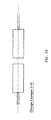
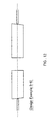
FIG. 1 is a schematic side view showing an optical system of an
optical device according to the present invention.
FIG. 2 is a schematic sectional view showing an embodiment of the
optical device according to the present invention.
FIG. 3 is a perspective view showing a rod lens used in the optical
device according to the present invention.
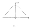
FIG. 4 is a schematic graph showing a refractive index distribution
curve of the rod lens used in the optical device according to the present
invention.
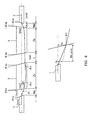
FIG. 5 is a schematic view for explaining the path of a center light
ray in an embodiment according to the present invention.
FIG. 6 is a schematic view for explaining the path of a center light
ray in another embodiment according to the present invention.
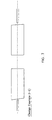
FIG. 7 is a schematic side view showing an optical system according
to Design Example 3-1 of the present invention.
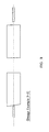
FIG. 8 is a schematic side view showing an optical system according
to Design Example 3-2 of the present invention.
FIG. 9 is a schematic side view showing an optical system according
to Design Example 3-3 of the present invention.
FIG. 10 is a schematic side view showing an optical system
according to Design Example 3-4 of the present invention.
FIG. 11 is a schematic side view showing an optical system
according to Design Example 3-5 of the present invention.
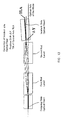
FIG. 12 is a schematic side view showing an optical system
according to Design Example 3-6 of the present invention.
FIG. 13 is a schematic side view showing an optical system of a
conventional optical device.
The present invention is described more specifically using
embodiments as follows.
FIG. 1 is a schematic side view showing an optical system of an
optical device according to an embodiment of the present invention. As
shown in FIG. 1, the optical device according to the present embodiment
includes an output fiber 1, a first rod lens 3, a second rod lens 4, and an input
fiber 2, which are arranged sequentially, and their optical axes all coincide.
The optical fibers (the output fiber 1 and the input fiber 2) of the
present invention are described on the premise that they are single-mode
fibers (whose working wavelength region is in the range of about 900 nm to
1600 nm) for optical communication. However, it should be appreciated
that they can be step-index type or refractive index distribution type
multimode fibers used in other wavelength regions.
The end faces (facing the rod lenses) of the output fiber 1 and the
input fiber 2 are processed to have slopes so that crosstalk caused by
reflected light can be prevented. In this case, it is desirable that the angle
between a line normal to each end face and an optical axis of each optical
fiber is in the range of 4° to 15°. In other words, when the angle between
the line normal to an outgoing face of the output fiber 1 and an optical axis (a
Z axis) of the optical device as a whole is indicated as FA and the angle
between the line normal to an incident face of the input fiber 2 and the
optical axis (the Z axis) as FB , preferably the angles FA and FB satisfy
Eq. 21 4 • (π/180) ≤ | FA | ≤ 15 • (π/180)
and
Eq. 22 4 • (π/180) ≤ |FB | ≤ 15 • (π/180).
When the angles are smaller than 4°, a sufficient crosstalk
prevention effect cannot be obtained. On the other hand, when the angles
exceed 15°, there is a possibility that coma aberration may occur and
therefore coupling efficiency may decrease.
Generally, these angles are set to be in the range of 6° to 8°, which is
a more desirable range.
For the same reason, the end faces (facing the optical fibers) of the
first rod lens 3 and the second rod lens 4 also are processed to have slopes.
In this case, the angle between the line normal to an incident face of the first
rod lens 3 and the optical axis (the Z axis) of the optical device as a whole is
indicated as PA, and the angle between the line normal to an outgoing face
of the second rod lens 4 and the optical axis (the Z axis) as PB .
Most of the single-mode fibers for optical communication have core-center
refractive indices of about 1.44 (values in the case of quartz) and NA
(a numeral aperture) values of about 0.1 (according to the definition at an
intensity of 1/e2). However, it should be appreciated that optical fibers with
other core-center refractive indices and NA values also can be used. The
core-center refractive index of the output fiber 1 is indicated as nFA , and that
of the input fiber 2 as nFB . Furthermore, the interval between the output
fiber 1 and the first rod lens 3 is indicated as WA , that between the second
rod lens 4 and the input fiber 2 as WB , that between the first rod lens 3 and
the second rod lens 4 as L, the refractive index of a medium between the
output fiber 1 and the first rod lens 3 as nLA , that of a medium between the
second rod lens 4 and the input fiber 2 as nLB , and that of a medium between
the first rod lens 3 and the second rod lens 4 as nM .
As shown in FIGs. 3 and 4, the refractive index n of the rod lens 7
used in the present invention distributes in its radial direction, and the
refractive index distribution in the working wavelength region is expressed
by
Eq. 23 n(r)2 = n0 2 • {1 - (g • r)2 + h4 • (g • r)4 + h6 • (g • r)6 + h8 • (g • r)8 + •••},
wherein r denotes a radial distance from an optical axis 7a of the rod lens 7,
n(r) a refractive index at the radial distance r from the optical axis 7a of the
rod lens 7, n0 a refractive index on the optical axis 7a of the rod lens 7 (center
refractive index), and g, h4, h6, and h8 refractive index distribution
coefficients. In FIG. 3, r0 indicates the radius of the rod lens 7.
Preferably, the outer diameter 2r0 of the rod lens 7 is in the range of
0.125 mm to 5 mm. Since the standard of the clad outer diameter in an
optical fiber is 0.125 mm, it is preferable that the outer diameter of the rod
lens 7 is larger than this. When the outer diameter of the rod lens 7 exceeds
5 mm, it becomes difficult to reduce the size and weight of the optical device
as a whole. An outer diameter of 1.8 mm is a practical international
standard and therefore, is particularly preferable.
The lower limit of the center refractive index n0 of the rod lens 7 is
about 1.4 when glass or plastic is used as the material of the rod lens 7.
When glass is used as the material of the rod lens 7 and a larger amount of
component contributing to increase in refractive index, such as lead oxide,
lanthanum oxide, or the like, is used so that the center refractive index n0
increases to exceed 2.0, there arise problems in that the ion-exchange rate is
reduced considerably and devitrification tends to occur easily.
The brightness of the rod lens 7 is defined by an angular aperture
= n0 · g · r0 (rad) indicating the range over which the lens can accept light.
Preferably, this angular aperture = n0 · g · r0 is in the range of 0.1 ≤ n0 · g
· r0 ≤ 1.0. A value of n0 · g · r0 smaller than 0.1 results in a smaller
numerical aperture NA. Therefore, it becomes difficult to collect all of the
light leaving from the optical fiber and thus an eclipse loss increases. On
the other hand, it is difficult to manufacture a rod lens having a large
difference in refractive index and a value of n0 · g · r0 exceeding 1.0. A
further preferable range of n0 · g · r0 is 0.15 ≤ n0 · g · r0 ≤ 0.60, wherein the
rod lens 7 can be manufactured easily.
An aberration in the rod lens 7 is determined by the refractive index
distribution coefficients h4 , h6 , h8 ···. Under the application conditions in
the present invention, if h4 = +0.67, the spherical aberration is substantially
within the diffraction limit when the numerical aperture NA is 0.2 or less,
and therefore, a sufficient performance can be obtained. In order to reduce
the aberration further, the values of h6 , h8 ··· may be optimized.
When the one-pitch length P of the rod lens 7 is defined as P = 2π / g
and the length Z on the optical axis of the rod lens 7 is set to be equal to
0.25P, parallel light rays entering from the end face on one side are allowed
to form an image on the end face on the other side. In actual use, preferably
the value of Z is set to be 0.23 P to 0.25 P so that the interval between the rod
lens 7 and an optical fiber is provided in some degree. However, it also is
possible to set the value of Z to be less than 0.23 P to increase the interval or
to be slightly larger than 0.25 P so as to compensate for beam spread due to
the Gaussian beam.
The length of the first rod lens 3 in its optical axis (the Z axis)
direction is indicated as ZA. The refractive index nA of the first rod lens 3
has a radial distribution as described above, and the refractive index
distribution in the working wavelength region is expressed by
Eq. 24 nA(r)2 = n0A 2 • {1 - (gA • r)2 + h4A (gA • r)4
+ h6A (gA • r)6 + h8A (gA •r)8 + •••},
wherein r denotes a radial distance from the optical axis of the first rod lens
3, nA(r) the refractive index at the radial distance r from the optical axis of
the first rod lens 3, n0A the refractive index on the optical axis of the first rod
lens 3 (center refractive index), and gA , h4A, h6A, and h8A refractive index
distribution coefficients.
The length of the second rod lens 4 in its optical axis (the Z axis)
direction is indicated as ZB . The refractive index nB of the second rod lens 4
also has a radial distribution and the refractive index distribution in the
working wavelength region is expressed by
Eq. 25 nB(r)2 = n0B 2 • {1 - (gB • r)2 + h4B (gB • r)4
+ h6B (gB • r)6 + h8B (gB • r)8 + •••},
wherein r denotes a radial distance from the optical axis of the second rod
lens 4, nB(r) the refractive index at the radial distance r from the optical axis
of the second rod lens 4, n0B the refractive index on the optical axis of the
second rod lens 4 (center refractive index), and gB , h4B, h6B, and h8B refractive
index distribution coefficients.
FIG. 5 is a schematic view showing the path of a center light ray
leaving the output fiber. In this case, FA > 0 and FB > 0, and the
relationship of
Eq. 26 FA • FB > 0
is satisfied.
After the center light ray of a beam leaving the output fiber 1 enters
the input fiber 2, its path coincides with the optical axis of the whole.
With respect to the output fiber 1 and the first rod lens 3 in the left
half shown in FIG. 5, when the small angle approximation (sin = ) is
applied to Snell's law, equations of
Eq. 27 nFA • FA = nLA • (FA + 1),
Eq. 28 h1 = WA • 1,
Eq. 29 nLA • (1 + PA) = n0A • (PA + 2),
Eq. 30 h2 = LA • 3A ,
and
Eq. 31 nM • (3 - QA) = n0A • (4 - QA)
are obtained, wherein both h1 and h2 are least values and therefore the
refractive index of the first rod lens 3 is taken as n0A . In this case, the
intersection F of the center light ray and the optical axis of the whole is
located at the midpoint between the rod lenses 3 and 4 (i.e. LA = LB = 0.5L).
The length of the rod lenses is substantially equal to a 1/4 pitch
length of the rod lenses and WA and WB are least values. Therefore,
relationships of
Eq. 32 gA • h1 = 4
and
Eq. 33 gA • h2 = 2
are obtained in an approximate manner.
At the point F, the relationship of 3A = 3B is required to be satisfied.
From the above relative equations, 3A and 3B are defined by
Eq. 34 3A = n0A • gA • WA • (nFA - nLA) FA / (nM • nLA) + (nM - n0A) • QA /nM
and
Eq. 35 3B = n0B • gB • WB • (nFB - nLB) FB / (nM • nLB)
+ (nM - n0B) • QB / nM.
The relative equations 34 and 35 contain errors due to the small
angle approximation. When consideration is given to the errors, the
condition substantially to be satisfied is expressed as
Eq. 36 0 ≤ |3A - 3B | ≤ π / 180.
With respect to QA and QB that are not included in the above
equations 34 and 35, when 1, 2, 3A , 4, h1 , and h2 are eliminated from the
above relative equations, a relationship of
Eq. 37 QA = {(0.5 • n0A 2 • g A 2 • L • WA - nLA • nM) •
(nFA - nLA) FA + nLA • nM (n0A - nLA) • PA }
/ {0.5 • n0A • nLA • gA • L • (n0A - nM)}
is obtained.
The value defined in the right side of the above equation 37 is
redefined as QA0.
Similarly, regarding the second rod lens 4 and the input fiber 2, a
relationship of
Eq. 38 QB = {(0.5 • n0B 2 • gB 2 • L • WB - nLB • nM) • (nFB - nLB) FB + nLB • nM (n0B - nLB) • PB} / {0.5 • n0B • nLB • gB • L • (n0B - nM)}
is obtained.
The value defined in the right side of the above equation 38 is
redefined as QB0 .
In the equations 37 and 38, when L = 0, QA0 = QB0 = 0.
The relative equations 37 and 38 contain errors due to the small
angle approximation. When consideration is given to the errors, actual QA
and QB are different from QA0 and QB0 , and the conditions substantially to
be satisfied are expressed by
Eq. 39 - 2.5 • (π / 180) ≤ QA - QA0 ≤ + 2.5 • (π / 180)
and
- 2.5 • (π / 180) ≤ QB - QB0 ≤ + 2.5 • (π / 180).
When LA = LB = 0.5L, the conditions of the equation 39 substantially
are satisfied and an excellent symmetry of the whole optical system is
obtained, which enables the respective rod lenses to have the same shape
and therefore, is preferable. However, when the point F is shifted
considerably from the midpoint of both rod lenses, the equation 39 is not
satisfied and the condition to be satisfied is expressed as
Eq. 40 - 2.5 • (π / 180) ≤ (QA + QB) - (QA0 + QB0) ≤ + 2.5 • (π / 180).
When either the equation 36 or the equations 36 and 40 is satisfied,
the angles of the faces of the first and second rod lenses 3 and 4 processed to
have slopes are optimized and in the configuration including the output fiber
1, the first rod lens 3, the second rod lens 4, and the input fiber 2 with their
optical axes all being allowed to coincide, the path of a center light ray
entering the input fiber 2 is allowed to coincide with the optical axis of the
whole. As a result, the assembly and adjustment of the optical device can be
simplified considerably, and thus the production cost can be reduced. In
other words, as shown in FIG. 2, the optical device can be assembled by a
simple process including maintaining the output fiber 1 and the input fiber 2
with the ferrules 5 with the same outer diameter as those of the first and
second rod lenses 3 and 4 and sequentially inserting the input fiber 2, the
second rod lens 4, the first rod lens 3, and the output fiber 1 into the single
sleeve 6.
FIG. 6 is a schematic view showing a path of a center light ray
leaving an output fiber in another example of optical devices according to the
present invention.
In the optical device of the present invention, as shown in FIG. 6, an
output fiber 1, a first rod lens 3, a second rod lens 4, and an input fiber 2 may
be arranged so that a face of the output fiber 1 facing the first rod lens 3 and
a face of the input fiber 2 facing the second rod lens 4 have substantial plane
symmetry, i.e. so that a relationship of
Eq. 41 FA • FB < 0
is satisfied.
After the center light ray of a beam leaving the output fiber 1 enters
the input fiber 2, its path coincides with the optical axis of the whole.
In this case, the center light ray may be allowed to be parallel to the
optical axis of the whole regardless of the interval L.
With respect to the output fiber 1 and the first rod lens 3 in the left
half shown in FIG. 6, when the small angle approximation (sin = ) is
applied to Snell's law, equations of
Eq. 42 nFA • FA = nLA • (FA + 1),
Eq. 43 h1 = WA • 1 ,
Eq. 44 nL • (1 + PA) = n0A • (PA + 2),
and
Eq. 45 - nM • QA = n0A • (4 - QA)
are obtained.
When the length of the rod lenses is a 1/4 pitch length of the rod
lenses, the approximation of
Eq. 46 4 = gA • h1
is obtained. However, when the interval WA is corrected, relationships of
Eq. 47 4 = gA • h1'
and
Eq. 48 h1' = h1 - n0 • WA • 2 / nL
are obtained.
When 1, 2, 4 , h1 , and h1 , are eliminated from the above relative
equations (except for the equation 46), a relationship of
Eq. 49 QA = n0A • gA • WA • (n0A - DLA) • PA / {nLA • (n0A - nM)}
is obtained.
The value defined in the right side of the above equation 49 is
redefined as QA0 (when n0A - nM = 0, QA0 = 0).
Similarly, regarding the second rod lens 4 and the input fiber 2, a
relationship of
Eq. 50 QB = n0B • gB • WB • (n0B-nLB) • PB/{nLB · (n0B-nM)}
is obtained.
The value defined in the right side of the above equation 50 is
redefined as QB0 (when n0B - nM = 0, QB0 = 0).
The relative equations 49 and 50 contain errors due to the small
angle approximation. When consideration is given to the errors, the
conditions substantially to be satisfied are expressed by
Eq. 51 - (π / 180) ≤ QA - QA0 ≤ (π / 180)
and
Eq. 52 - (π / 180) ≤ QB - QB0 ≤ (π / 180).
When the equations 51 and 52 are satisfied, the angles of the faces
of the first and second rod lenses 3 and 4 processed to have slopes are
optimized, and in the configuration including the output fiber 1, the first rod
lens 3, the second rod lens 4, and the input fiber 2 with their optical axes all
being allowed to coincide, the path of a center light ray entering the input
fiber 2 is allowed to coincide with the optical axis of the whole. As a result,
the assembly and adjustment of the optical device can be simplified
considerably, and thus the production cost can be reduced.
In an actual optical device, in both cases of positive and negative
values of
FA ·
FB , it is desirable to add the following conditions (6) to (12) to
reduce the kinds of components to improve productivity.
Since longer intervals WA and WB tend to cause coma aberrations, it
is desirable that relationships of
Eq. 53 gA • WA ≤ 0.2
and
Eq. 54 gB • WB ≤ 0.2
are satisfied.
Examples
The present invention is described further in detail with specific
examples.
The designs and coupling efficiency of optical systems were
calculated using an optical design software program "OSLO SIX"
manufactured by Sinclair Optics, U.S.A.
Design Examples 1-1 to 1-128 shown in Tables 2-1 to 5-3 below are
designed using a diameter 2r0 of rod lenses normalized as 1 in optical devices
with the configuration shown in FIG. 5. Every design example satisfies the
above-mentioned respective conditions. In every design example, after a
center light ray enters an input fiber, its path coincides with the optical axis
of the whole.
Design Examples 2-1 to 2-6 shown in Tables 6-1 to 6-3 below are
designed using a diameter 2r0 of the rod lenses normalized as 1 in optical
devices with the configuration shown in FIG. 6. In the design examples in
Tables 2-1 to 6-3, a fourth-order refractive index distribution coefficient h4 is
set to be +0.67, and sixth-order or higher-order refractive index distribution
coefficients all are set to be 0.
When specific values from the range of 0.125 mm ≤ 2
r0 ≤ 5 mm are
selected as
r0 in Tables 2-1 to 6-3, values of
W,
Z, and
L with a unit of length
may be set to be proportional to
r0 , and a value of
g with a unit of (length)
-1
may be set to be inversely proportional to
r0 . The refractive index
n and the
refractive index distribution coefficients
h4, h6, h8 ··· are dimensionless. In
addition, the unit of angle in Tables 2-1 to 6-3 is " ° (degrees) ".
| Des. Ex. No. | nFA | nFB | FA | FB | nLA | nLB | WA | WB | n0A | n0B |
| | | | ° | ° |
| 1-1 | 1.444 | 1.444 | 8.0 | 8.0 | 1.000 | 1.000 | 0.030 | 0.030 | 1.400 | 1.400 |
| 1-2 | 1.444 | 1.444 | 8.0 | 8.0 | 1.000 | 1.000 | 0.030 | 0.030 | 1.444 | 1.444 |
| 1-3 | 1.444 | 1.444 | 8.0 | 8.0 | 1.000 | 1.000 | 0.030 | 0.030 | 1.500 | 1.500 |
| 1-4 | 1.444 | 1.444 | 8.0 | 8.0 | 1.000 | 1.000 | 0.030 | 0.030 | 1.600 | 1.600 |
| 1-5 | 1.444 | 1.444 | 8.0 | 8.0 | 1.000 | 1.000 | 0.030 | 0.030 | 1.700 | 1.700 |
| 1-6 | 1.444 | 1.444 | 8.0 | 8.0 | 1.000 | 1.000 | 0.030 | 0.030 | 1.800 | 1.800 |
| 1-7 | 1.444 | 1.444 | 8.0 | 8.0 | 1.000 | 1.000 | 0.030 | 0.030 | 2.000 | 2.000 |
| 1-8 | 1.444 | 1.444 | 8.0 | 8.0 | 1.000 | 1.000 | 0.003 | 0.003 | 1.444 | 1.444 |
| 1-9 | 1.444 | 1.444 | 8.0 | 8.0 | 1.000 | 1.000 | 0.300 | 0.300 | 1.444 | 1.444 |
| 1-10 | 1.444 | 1.444 | 8.0 | 8.0 | 1.000 | 1.000 | 0.030 | 0.030 | 1.444 | 1.444 |
| 1-11 | 1.444 | 1.444 | 8.0 | 8.0 | 1.000 | 1.000 | 0.030 | 0.030 | 1.444 | 1.444 |
| 1-12 | 1.444 | 1.444 | 8.0 | 8.0 | 1.000 | 1.000 | 0.030 | 0.030 | 1.444 | 1.444 |
| 1-13 | 1.444 | 1.444 | 8.0 | 8.0 | 1.000 | 1.000 | 0.030 | 0.030 | 1.444 | 1.444 |
| 1-14 | 1.444 | 1.444 | 8.0 | 8.0 | 1.000 | 1.000 | 0.030 | 0.030 | 1.444 | 1.444 |
| 1-15 | 1.444 | 1.444 | 8.0 | 8.0 | 1.000 | 1.000 | 0.003 | 0.003 | 1.600 | 1.600 |
| 1-16 | 1.444 | 1.444 | 8.0 | 8.0 | 1.000 | 1.000 | 0.010 | 0.010 | 1.600 | 1.600 |
| 1-17 | 1.444 | 1.444 | 8.0 | 8.0 | 1.000 | 1.000 | 0.100 | 0.100 | 1.600 | 1.600 |
| 1-18 | 1.444 | 1.444 | 8.0 | 8.0 | 1.000 | 1.000 | 0.300 | 0.300 | 1.600 | 1.600 |
| 1-19 | 1.444 | 1.444 | 8.0 | 8.0 | 1.000 | 1.000 | 0.030 | 0.030 | 1.600 | 1.600 |
| 1-20 | 1.444 | 1.444 | 8.0 | 8.0 | 1.000 | 1.000 | 0.030 | 0.030 | 1.600 | 1.600 |
| 1-21 | 1.444 | 1.444 | 8.0 | 8.0 | 1.000 | 1.000 | 0.030 | 0.030 | 1.600 | 1.600 |
| 1-22 | 1.444 | 1.444 | 8.0 | 8.0 | 1.000 | 1.000 | 0.030 | 0.030 | 1.600 | 1.600 |
| 1-23 | 1.444 | 1.444 | 8.0 | 8.0 | 1.000 | 1.000 | 0.030 | 0.030 | 1.600 | 1.600 |
| 1-24 | 1.444 | 1.444 | 8.0 | 8.0 | 1.000 | 1.000 | 0.030 | 0.030 | 1.600 | 1.600 |
| 1-25 | 1.444 | 1.444 | 8.0 | 8.0 | 1.000 | 1.000 | 0.001 | 0.001 | 2.000 | 2.000 |
| 1-26 | 1.444 | 1.444 | 8.0 | 8.0 | 1.000 | 1.000 | 0.300 | 0.300 | 2.000 | 2.000 |
| 1-27 | 1.444 | 1.444 | 8.0 | 8.0 | 1.000 | 1.000 | 0.030 | 0.030 | 2.000 | 2.000 |
| 1-28 | 1.444 | 1.444 | 8.0 | 8.0 | 1.000 | 1.000 | 0.030 | 0.030 | 2.000 | 2.000 |
| 1-29 | 1.444 | 1.444 | 8.0 | 8.0 | 1.000 | 1.000 | 0.030 | 0.030 | 2.000 | 2.000 |
| 1-30 | 1.444 | 1.444 | 8.0 | 8.0 | 1.000 | 1.000 | 0.030 | 0.030 | 2.000 | 2.000 |
| 1-31 | 1.444 | 1.444 | 8.0 | 8.0 | 1.000 | 1.000 | 0.030 | 0.030 | 2.000 | 2.000 |
| 1-32 | 1.444 | 1.444 | 6.0 | 6.0 | 1.000 | 1.000 | 0.030 | 0.030 | 1.400 | 1.400 |
| Des. Ex. No. = Design Example Number |
| Des. Ex. No. | gA | gB | ZA | ZB | L | nM | PA | QA | QB | PB |
| | | | | | | | ° | ° | ° | ° |
| 1-1 | 0.600 | 0.600 | 2.575 | 2.575 | 1.0 | 1.0 | 8.78 | 0.00 | 0.00 | 8.78 |
| 1-2 | 0.600 | 0.600 | 2.573 | 2.573 | 1.0 | 1.0 | 7.92 | 0.00 | 0.00 | 7.92 |
| 1-3 | 0.600 | 0.600 | 2.572 | 2.572 | 1.0 | 1.0 | 7.04 | 0.00 | 0.00 | 7.04 |
| 1-4 | 0.600 | 0.600 | 2.569 | 2.569 | 1.0 | 1.0 | 5.87 | 0.00 | 0.00 | 5.87 |
| 1-5 | 0.600 | 0.600 | 2.566 | 2.566 | 1.0 | 1.0 | 5.03 | 0.00 | 0.00 | 5.03 |
| 1-6 | 0.600 | 0.600 | 2.563 | 2.563 | 1.0 | 1.0 | 4.40 | 0.00 | 0.00 | 4.40 |
| 1-7 | 0.600 | 0.600 | 2.556 | 2.556 | 1.0 | 1.0 | 3.51 | 0.00 | 0.00 | 3.51 |
| 1-8 | 0.600 | 0.600 | 2.614 | 2.614 | 1.0 | 1.0 | 7.98 | 0.00 | 0.00 | 8.06 |
| 1-9 | 0.600 | 0.600 | 2.183 | 2.183 | 1.0 | 1.0 | 7.64 | 0.00 | 0.00 | 7.46 |
| 1-10 | 0.600 | 0.600 | 2.574 | 2.574 | 0.0 | 1.0 | 8.01 | 0.00 | 0.00 | 8.01 |
| 1-11 | 0.600 | 0.600 | 2.574 | 2.574 | 10.0 | 1.0 | 7.20 | 0.00 | 0.00 | 7.20 |
| 1-12 | 0.600 | 0.600 | 2.574 | 2.574 | 30.0 | 1.0 | 6.00 | 0.00 | 0.00 | 5.99 |
| 1-13 | 0.200 | 0.200 | 7.81 | 7.81 | 1.0 | 1.0 | 7.99 | 0.00 | 0.00 | 7.99 |
| 1-14 | 1.000 | 1.000 | 1.526 | 1.526 | 1.0 | 1.0 | 7.77 | 0.00 | 0.00 | 7.77 |
| 1-15 | 0.600 | 0.600 | 2.614 | 2.614 | 1.0 | 1.0 | 5.94 | 0.00 | 0.00 | 5.95 |
| 1-16 | 0.600 | 0.600 | 2.601 | 2.601 | 1.0 | 1.0 | 5.92 | 0.00 | 0.00 | 5.92 |
| 1-17 | 0.600 | 0.600 | 2.455 | 2.455 | 1.0 | 1.0 | 5.74 | 0.00 | 0.00 | 5.74 |
| 1-18 | 0.600 | 0.600 | 2.141 | 2.141 | 1.0 | 1.0 | 5.67 | 0.00 | 0.00 | 5.67 |
| 1-19 | 0.600 | 0.600 | 2.569 | 2.569 | 0.0 | 1.0 | 5.95 | 0.00 | 0.00 | 5.95 |
| 1-20 | 0.600 | 0.600 | 2.569 | 2.569 | 3.0 | 1.0 | 5.71 | 0.00 | 0.00 | 5.71 |
| 1-21 | 0.600 | 0.600 | 2.569 | 2.569 | 10.0 | 1.0 | 5.23 | 0.00 | 0.00 | 5.28 |
| 1-22 | 0.600 | 0.600 | 2.569 | 2.569 | 30.0 | 1.0 | 4.21 | 0.00 | 0.00 | 4.21 |
| 1-23 | 0.200 | 0.200 | 7.805 | 7.805 | 1.0 | 1.0 | 5.94 | 0.00 | 0.00 | 5.94 |
| 1-24 | 1.000 | 1.000 | 1.522 | 1.522 | 1.0 | 1.0 | 5.74 | 0.00 | 0.00 | 5.74 |
| 1-25 | 0.600 | 0.600 | 2.615 | 2.615 | 1.0 | 1.0 | 3.57 | 0.00 | 0.00 | 3.57 |
| 1-26 | 0.600 | 0.600 | 2.031 | 2.031 | 1.0 | 1.0 | 3.33 | 0.00 | 0.00 | 3.34 |
| 1-27 | 0.600 | 0.600 | 2.556 | 2.556 | 0.0 | 1.0 | 3.58 | 0.00 | 0.00 | 3.58 |
| 1-28 | 0.600 | 0.600 | 2.557 | 2.557 | 10.0 | 1.0 | 2.95 | 0.00 | 0.00 | 2.95 |
| 1-29 | 0.600 | 0.600 | 2.557 | 2.557 | 30.0 | 1.0 | 2.18 | 0.00 | 0.00 | 2.19 |
| 1-30 | 0.200 | 0.200 | 7.793 | 7.793 | 1.0 | 1.0 | 3.57 | 0.00 | 0.00 | 3.57 |
| 1-31 | 1.000 | 1.000 | 1.509 | 1.509 | 1.0 | 1.0 | 3.39 | 0.00 | 0.00 | 3.39 |
| 1-32 | 0.600 | 0.600 | 2.575 | 2.575 | 1.0 | 1.0 | 6.59 | 0.00 | 0.00 | 6.59 |
| Des. Ex. No. = Design Example Number |
| Des. Ex. No. | QA0 | QB0 | QA-QA0 | QB-QB0 | (QA+QB) -(QA0+ QB0) | 3A | 3B | 3A-3B |
| | ° | ° | ° | ° | ° | ° | ° | ° |
| 1-1 | -0.02 | -0.03 | 0.024 | 0.026 | 0.05 | 0.090 | 0.090 | 0.000 |
| 1-2 | 0.02 | 0.01 | -0.016 | -0.014 | -0.03 | 0.092 | 0.092 | 0.000 |
| 1-3 | 0.04 | 0.04 | -0.043 | -0.043 | -0.09 | 0.096 | 0.096 | 0.000 |
| 1-4 | 0.06 | 0.06 | -0.062 | -0.062 | -0.12 | 0.102 | 0.102 | 0.000 |
| 1-5 | 0.06 | 0.07 | -0.063 | -0.066 | -0.13 | 0.109 | 0.109 | 0.000 |
| 1-6 | 0.06 | 0.06 | -0.062 | -0.062 | -0.12 | 0.115 | 0.115 | 0.000 |
| 1-7 | 0.05 | 0.05 | -0.055 | -0.055 | -0.11 | 0.128 | 0.128 | 0.000 |
| 1-8 | -0.03 | 0.16 | 0.027 | -0.160 | -0.13 | 0.009 | 0.009 | 0.000 |
| 1-9 | 1.25 | 0.82 | -1.251 | -0.824 | -2.07 | 0.923 | 0.923 | 0.000 |
| 1-10 | 0.00 | 0.00 | 0.000 | 0.000 | 0.00 | 0.092 | 0.092 | 0.000 |
| 1-11 | 0.02 | 0.02 | -0.023 | -0.022 | -0.05 | 0.092 | 0.092 | 0.000 |
| 1-12 | 0.05 | 0.05 | -0.054 | -0.053 | -0.11 | 0.092 | 0.092 | 0.000 |
| 1-13 | 0.01 | 0.00 | -0.007 | 0.000 | -0.01 | 0.031 | 0.031 | 0.000 |
| 1-14 | 0.03 | 0.03 | -0.034 | -0.031 | -0.06 | 0.154 | 0.154 | 0.000 |
| 1-15 | 0.05 | 0.07 | -0.052 | -0.073 | -0.12 | 0.009 | 0.009 | 0.000 |
| 1-16 | 0.05 | 0.05 | -0.053 | -0.048 | -0.10 | 0.034 | 0.034 | 0.000 |
| 1-17 | 0.18 | 0.18 | -0.185 | -0.185 | -0.37 | 0.341 | 0.341 | 0.000 |
| 1-18 | 1.18 | 1.18 | -1.180 | -1.178 | -2.36 | 1.023 | 1.023 | 0.000 |
| 1-19 | 0.00 | 0.00 | 0.000 | 0.000 | 0.00 | 0.102 | 0.102 | 0.000 |
| 1-20 | 0.03 | 0.03 | -0.027 | -0.026 | -0.05 | 0.102 | 0.102 | 0.000 |
| 1-21 | 0.03 | 0.04 | -0.027 | -0.037 | -0.06 | 0.102 | 0.102 | 0.000 |
| 1-22 | 0.05 | 0.05 | -0.052 | -0.052 | -0.10 | 0.102 | 0.102 | 0.000 |
| 1-23 | 0.16 | 0.15 | -0.157 | -0.151 | -0.31 | 0.034 | 0.034 | 0.000 |
| 1-24 | 0.06 | 0.06 | -0.057 | -0.057 | -0.11 | 0.170 | 0.170 | 0.000 |
| 1-25 | 0.04 | 0.04 | -0.036 | -0.041 | -0.08 | 0.006 | 0.006 | 0.000 |
| 1-26 | 0.91 | 0.92 | -0.910 | -0.917 | -1.83 | 1.279 | 1.279 | 0.000 |
| 1-27 | 0.00 | 0.00 | 0.000 | 0.000 | 0.00 | 0.128 | 0.128 | 0.000 |
| 1-28 | 0.03 | 0.03 | -0.027 | -0.028 | -0.05 | 0.128 | 0.128 | 0.000 |
| 1-29 | 0.05 | 0.05 | -0.051 | -0.052 | -0.10 | 0.128 | 0.128 | 0.000 |
| 1-30 | 0.14 | 0.14 | -0.138 | -0.138 | -0.28 | 0.043 | 0.043 | 0.000 |
| 1-31 | 0.05 | 0.05 | -0.049 | -0.050 | -0.10 | 0.213 | 0.213 | 0.000 |
| 1-32 | -0.01 | -0.01 | 0.006 | 0.006 | 0.01 | 0.067 | 0.067 | 0.000 |
| Des. Ex. No. = Design Example Number |
| Des. Ex. No. | nFA | nFB | FA | FB | nLA | nLB | WA | WB | n0A | n0B |
| | | | ° | ° |
| 1-33 | 1.444 | 1.444 | 6.0 | 6.0 | 1.000 | 1.000 | 0.030 | 0.030 | 1.444 | 1.444 |
| 1-34 | 1.444 | 1.444 | 6.0 | 6.0 | 1.000 | 1.000 | 0.030 | 0.030 | 1.500 | 1.500 |
| 1-35 | 1.444 | 1.444 | 6.0 | 6.0 | 1.000 | 1.000 | 0.030 | 0.030 | 1.600 | 1.600 |
| 1-36 | 1.444 | 1.444 | 6.0 | 6.0 | 1.000 | 1.000 | 0.030 | 0.030 | 1.700 | 1.700 |
| 1-37 | 1.444 | 1.444 | 6.0 | 6.0 | 1.000 | 1.000 | 0.030 | 0.030 | 1.800 | 1.800 |
| 1-38 | 1.444 | 1.444 | 6.0 | 6.0 | 1.000 | 1.000 | 0.030 | 0.030 | 2.000 | 2.000 |
| 1-39 | 1.444 | 1.444 | 6.0 | 6.0 | 1.000 | 1.000 | 0.006 | 0.006 | 1.444 | 1.444 |
| 1-40 | 1.444 | 1.444 | 6.0 | 6.0 | 1.000 | 1.000 | 0.300 | 0.300 | 1.444 | 1.444 |
| 1-41 | 1.444 | 1.444 | 6.0 | 6.0 | 1.000 | 1.000 | 0.030 | 0.030 | 1.444 | 1.444 |
| 1-42 | 1.444 | 1.444 | 6.0 | 6.0 | 1.000 | 1.000 | 0.030 | 0.030 | 1.444 | 1.444 |
| 1-43 | 1.444 | 1.444 | 6.0 | 6.0 | 1.000 | 1.000 | 0.030 | 0.030 | 1.444 | 1.444 |
| 1-44 | 1.444 | 1.444 | 6.0 | 6.0 | 1.000 | 1.000 | 0.030 | 0.030 | 1.444 | 1.444 |
| 1-45 | 1.444 | 1.444 | 6.0 | 6.0 | 1.000 | 1.000 | 0.030 | 0.030 | 1.444 | 1.444 |
| 1-46 | 1.444 | 1.444 | 6.0 | 6.0 | 1.000 | 1.000 | 0.005 | 0.005 | 1.600 | 1.600 |
| 1-47 | 1.444 | 1.444 | 6.0 | 6.0 | 1.000 | 1.000 | 0.300 | 0.300 | 1.600 | 1.600 |
| 1-48 | 1.444 | 1.444 | 6.0 | 6.0 | 1.000 | 1.000 | 0.030 | 0.030 | 1.600 | 1.600 |
| 1-49 | 1.444 | 1.444 | 6.0 | 6.0 | 1.000 | 1.000 | 0.030 | 0.030 | 1.600 | 1.600 |
| 1-50 | 1.444 | 1.444 | 6.0 | 6.0 | 1.000 | 1.000 | 0.030 | 0.030 | 1.600 | 1.600 |
| 1-51 | 1.444 | 1.444 | 6.0 | 6.0 | 1.000 | 1.000 | 0.030 | 0.030 | 1.600 | 1.600 |
| 1-52 | 1.444 | 1.444 | 6.0 | 6.0 | 1.000 | 1.000 | 0.030 | 0.030 | 1.600 | 1.600 |
| 1-53 | 1.444 | 1.444 | 6.0 | 6.0 | 1.000 | 1.000 | 0.002 | 0.002 | 2.000 | 2.000 |
| 1-54 | 1.444 | 1.444 | 6.0 | 6.0 | 1.000 | 1.000 | 0.300 | 0.300 | 2.000 | 2.000 |
| 1-55 | 1.444 | 1.444 | 6.0 | 6.0 | 1.000 | 1.000 | 0.030 | 0.030 | 2.000 | 2.000 |
| 1-56 | 1.444 | 1.444 | 6.0 | 6.0 | 1.000 | 1.000 | 0.030 | 0.030 | 2.000 | 2.000 |
| 1-57 | 1.444 | 1.444 | 6.0 | 6.0 | 1.000 | 1.000 | 0.030 | 0.030 | 2.000 | 2.000 |
| 1-58 | 1.444 | 1.444 | 6.0 | 6.0 | 1.000 | 1.000 | 0.030 | 0.030 | 2.000 | 2.000 |
| 1-59 | 1.444 | 1.444 | 6.0 | 6.0 | 1.000 | 1.000 | 0.030 | 0.030 | 2.000 | 2.000 |
| 1-60 | 1.444 | 1.444 | 4.0 | 4.0 | 1.000 | 1.000 | 0.030 | 0.030 | 1.400 | 1.400 |
| 1-61 | 1.444 | 1.444 | 4.0 | 4.0 | 1.000 | 1.000 | 0.030 | 0.030 | 1.444 | 1.444 |
| 1-62 | 1.444 | 1.444 | 4.0 | 4.0 | 1.000 | 1.000 | 0.030 | 0.030 | 1.500 | 1.500 |
| 1-63 | 1.444 | 1.444 | 4.0 | 4.0 | 1.000 | 1.000 | 0.030 | 0.030 | 1.600 | 1.600 |
| 1-64 | 1.444 | 1.444 | 4.0 | 4.0 | 1.000 | 1.000 | 0.030 | 0.030 | 1.700 | 1.700 |
| Des. Ex. No. = Design Example Number |
| Des. Ex. No. | gA | gB | ZA | ZB | L | nM | PA | QA | QB | PB |
| | | | | | | | ° | ° | ° | ° |
| 1-33 | 0.600 | 0.600 | 2.574 | 2.574 | 1.0 | 1.0 | 5.94 | 0.00 | 0.00 | 5.94 |
| 1-34 | 0.600 | 0.600 | 2.572 | 2.572 | 1.0 | 1.0 | 5.27 | 0.00 | 0.00 | 5.27 |
| 1-35 | 0.600 | 0.600 | 2.569 | 2.569 | 1.0 | 1.0 | 4.39 | 0.00 | 0.00 | 4.39 |
| 1-36 | 0.600 | 0.600 | 2.566 | 2.566 | 1.0 | 1.0 | 3.76 | 0.00 | 0.00 - | 3.76 |
| 1-37 | 0.600 | 0.600 | 2.563 | 2.563 | 1.0 | 1.0 | 3.29 | 0.00 | 0.00 | 3.29 |
| 1-38 | 0.600 | 0.600 | 2.557 | 2.557 | 1.0 | 1.0 | 2.62 | 0.00 | 0.00 | 2.62 |
| 1-39 | 0.600 | 0.600 | 2.61 | 2.61 | 1.0 | 1.0 | 6.00 | 0.00 | 0.00 | 5.98 |
| 1-40 | 0.600 | 0.600 | 2.188 | 2.188 | 1.0 | 1.0 | 5.77 | 0.00 | 0.00 | 5.77 |
| 1-41 | 0.600 | 0.600 | 2.574 | 2.574 | 0.0 | 1.0 | 6.00 | 0.00 | 0.00 | 6.00 |
| 1-42 | 0.600 | 0.600 | 2.574 | 2.574 | 10.0 | 1.0 | 5.40 | 0.00 | 0.00 | 5.40 |
| 1-43 | 0.600 | 0.600 | 2.574 | 2.574 | 30.0 | 1.0 | 4.50 | 0.00 | 0.00 | 4.50 |
| 1-44 | 0.200 | 0.200 | 7.81 | 7.81 | 1.0 | 1.0 | 5.99 | 0.00 | 0.00 | 5.99 |
| 1-45 | 1.000 | 1.000 | 1.527 | 1.527 | 1.0 | 1.0 | 5.83 | 0.00 | 0.00 | 5.83 |
| 1-46 | 0.600 | 0.600 | 2.61 | 2.61 | 1.0 | 1.0 | 4.45 | 0.00 | 0.00 | 4.43 |
| 1-47 | 0.600 | 0.600 | 2.144 | 2.144 | 1.0 | 1.0 | 4.24 | 0.00 | 0.00 | 4.24 |
| 1-48 | 0.600 | 0.600 | 2.569 | 2.569 | 0.0 | 1.0 | 4.45 | 0.00 | 0.00 | 4.45 |
| 1-49 | 0.600 | 0.600 | 2.569 | 2.569 | 10.0 | 1.0 | 3.91 | 0.00 | 0.00 | 3.91 |
| 1-50 | 0.600 | 0.600 | 2.569 | 2.569 | 30.0 | 1.0 | 3.15 | 0.00 | 0.00 | 3.16 |
| 1-51 | 0.200 | 0.200 | 7.806 | 7.806 | 1.0 | 1.0 | 4.44 | 0.00 | 0.00 | 4.44 |
| 1-52 | 1.000 | 1.000 | 1.522 | 1.522 | 1.0 | 1.0 | 4.30 | 0.00 | 0.00 | 4.30 |
| 1-53 | 0.600 | 0.600 | 2.613 | 2.613 | 1.0 | 1.0 | 2.69 | 0.00 | 0.00 | 2.66 |
| 1-54 | 0.600 | 0.600 | 2.033 | 2.033 | 1.0 | 1.0 | 2.49 | 0.00 | 0.00 | 2.49 |
| 1-55 | 0.600 | 0.600 | 2.557 | 2.557 | 0.0 | 1.0 | 2.68 | 0.00 | 0.00 | 2.68 |
| 1-56 | 0.600 | 0.600 | 2.557 | 2.557 | 10.0 | 1.0 | 2.20 | 0.00 | 0.00 | 2.21 |
| 1-57 | 0.600 | 0.600 | 2.557 | 2.557 | 30.0 | 1.0 | 1.63 | 0.00 | 0.00 | 1.64 |
| 1-58 | 0.200 | 0.200 | 7.793 | 7.793 | 1.0 | 1.0 | 2.67 | 0.00 | 0.00 | 2.67 |
| 1-59 | 1.000 | 1.000 | 1.51 | 1.51 | 1.0 | 1.0 | 2.53 | 0.00 | 0.00 | 2.53 |
| 1-60 | 0.600 | 0.600 | 2.575 | 2.575 | 1.0 | 1.0 | 4.39 | 0.00 | 0.00 | 4.39 |
| 1-61 | 0.600 | 0.600 | 2.574 | 2.574 | 1.0 | 1.0 | 3.96 | 0.00 | 0.00 | 3.96 |
| 1-62 | 0.600 | 0.600 | 2.572 | 2.572 | 1.0 | 1.0 | 3.51 | 0.00 | 0.00 | 3.51 |
| 1-63 | 0.600 | 0.600 | 2.568 | 2.568 | 1.0 | 1.0 | 2.93 | 0.00 | 0.00 | 2.93 |
| 1-64 | 0.600 | 0.600 | 2.566 | 2.566 | 1.0 | 1.0 | 2.50 | 0.00 | 0.00 | 2.50 |
| Des. Ex. No. = Design Example Number |
| Des. Ex. No. | QA0 | QB0 | QA- QA0 | QB- QB0 | (QA + QB) -(QA0+ QB0) | 3A | 3B | 3A-3B |
| | ° | ° | ° | ° | ° | ° | ° | ° |
| 1-33 | 0.01 | 0.01 | -0.011 | -0.011 | -0.02 | 0.069 | 0.069 | 0.000 |
| 1-34 | 0.02 | 0.02 | -0.024 | -0.019 | -0.04 | 0.072 | 0.072 | 0.000 |
| 1-35 | 0.03 | 0.03 | -0.030 | -0.030 | -0.06 | 0.077 | 0.077 | 0.000 |
| 1-36 | 0.03 | 0.03 | -0.031 | -0.031 | -0.06 | 0.082 | 0.082 | 0.000 |
| 1-37 | 0.03 | 0.03 | -0.030 | -0.030 | -0.06 | 0.086 | 0.086 | 0.000 |
| 1-38 | 0.03 | 0.03 | -0.026 | -0.026 | -0.05 | 0.096 | 0.096 | 0.000 |
| 1-39 | 0.03 | -0.03 | -0.026 | 0.027 | 0.00 | 0.013 | 0.013 | 0.000 |
| 1-40 | 1.02 | 1.02 | -1.017 | -1.017 | -2.03 | 0.692 | 0.692 | 0.000 |
| 1-41 | 0.00 | 0.00 | 0.000 | 0.000 | 0.00 | 0.069 | 0.069 | 0.000 |
| 1-42 | 0.02 | 0.02 | -0.017 | -0.017 | -0.03 | 0.069 | 0.069 | 0.000 |
| 1-43 | 0.04 | 0.04 | -0.040 | -0.040 | -0.08 | 0.069 | 0.069 | 0.000 |
| 1-44 | 0.00 | 0.00 | -0.004 | -0.004 | -0.01 | 0.023 | 0.023 | 0.000 |
| 1-45 | 0.03 | 0.02 | -0.029 | -0.018 | -0.05 | 0.115 | 0.115 | 0.000 |
| 1-46 | 0.04 | 0.00 | -0.040 | -0.001 | -0.04 | 0.012 | 0.012 | 0.000 |
| 1-47 | 0.86 | 0.86 | -0.860 | -0.864 | -1.72 | 0.767 | 0.767 | 0.000 |
| 1-48 | 0.00 | 0.00 | 0.000 | 0.000 | 0.00 | 0.077 | 0.077 | 0.000 |
| 1-49 | 0.02 | 0.02 | -0.018 | -0.018 | -0.04 | 0.077 | 0.077 | 0.000 |
| 1-50 | 0.04 | 0.04 | -0.038 | -0.039 | -0.08 | 0.077 | 0.077 | 0.000 |
| 1-51 | 0.07 | 0.07 | -0.068 | -0.068 | -0.14 | 0.026 | 0.026 | 0.000 |
| 1-52 | 0.03 | 0.03 | -0.032 | -0.033 | -0.06 | 0.128 | 0.128 | 0.000 |
| 1-53 | 0.04 | -0.01 | -0.043 | 0.006 | -0.04 | 0.008 | 0.008 | 0.000 |
| 1-54 | 0.66 | 0.66 | -0.664 | -0.664 | -1.33 | 0.959 | 0.959 | 0.000 |
| 1-55 | 0.00 | 0.00 | 0.000 | 0.000 | 0.00 | 0.096 | 0.096 | 0.000 |
| 1-56 | 0.02 | 0.02 | -0.019 | -0.020 | -0.04 | 0.096 | 0.096 | 0.000 |
| 1-57 | 0.04 | 0.04 | -0.038 | -0.039 | -0.08 | 0.096 | 0.096 | 0.000 |
| 1-58 | 0.06 | 0.06 | -0.057 | -0.057 | -0.11 | 0.032 | 0.032 | 0.000 |
| 1-59 | 0.03 | 0.03 | -0.028 | -0.030 | -0.06 | 0.160 | 0.160 | 0.000 |
| 1-60 | 0.00 | 0.00 | -0.004 | -0.003 | -0.01 | 0.045 | 0.045 | 0.000 |
| 1-61 | 0.01 | 0.01 | -0.007 | -0.007 | -0.01 | 0.046 | 0.046 | 0.000 |
| 1-62 | 0.01 | 0.01 | -0.009 | -0.009 | -0.02 | 0.048 | 0.048 | 0.000 |
| 1-63 | 0.01 | 0.01 | -0.012 | -0.012 | -0.02 | 0.051 | 0.051 | 0.000 |
| 1-64 | 0.01 | 0.01 | -0.013 | -0.013 | -0.03 | 0.054 | 0.054 | 0.000 |
| Des. Ex. No. = Design Example Number |
| Des. Ex. No. | nFA | nFB | FA | FB | nLA | nLB | WA | WB | n0A | n0B |
| | | | ° | ° |
| 1-65 | 1.444 | 1.444 | 4.0 | 4.0 | 1.000 | 1.000 | 0.030 | 0.030 | 1.800 | 1.800 |
| 1-66 | 1.444 | 1.444 | 4.0 | 4.0 | 1.000 | 1.000 | 0.030 | 0.030 | 2.000 | 2.000 |
| 1-67 | 1.444 | 1.444 | 4.0 | 4.0 | 1.000 | 1.000 | 0.013 | 0.013 | 1.444 | 1.444 |
| 1-68 | 1.444 | 1.444 | 4.0 | 4.0 | 1.000 | 1.000 | 0.300 | 0.300 | 1.444 | 1.444 |
| 1-69 | 1.444 | 1.444 | 4.0 | 4.0 | 1.000 | 1.000 | 0.030 | 0.030 | 1.444 | 1.444 |
| 1-70 | 1.444 | 1.444 | 4.0 | 4.0 | 1.000 | 1.000 | 0.030 | 0.030 | 1.444 | 1.444 |
| 1-71 | 1.444 | 1.444 | 4.0 | 4.0 | 1.000 | 1.000 | 0.030 | 0.030 | 1.444 | 1.444 |
| 1-72 | 1.444 | 1.444 | 4.0 | 4.0 | 1.000 | 1.000 | 0.030 | 0.030 | 1.444 | 1.444 |
| 1-73 | 1.444 | 1.444 | 4.0 | 4.0 | 1.000 | 1.000 | 0.030 | 0.030 | 1.444 | 1.444 |
| 1-74 | 1.444 | 1.444 | 4.0 | 4.0 | 1.000 | 1.000 | 0.008 | 0.008 | 1.700 | 1.700 |
| 1-75 | 1.444 | 1.444 | 4.0 | 4.0 | 1.000 | 1.000 | 0.300 | 0.300 | 1.700 | 1.700 |
| 1-76 | 1.444 | 1.444 | 4.0 | 4.0 | 1.000 | 1.000 | 0.030 | 0.030 | 1.700 | 1.700 |
| 1-77 | 1.444 | 1.444 | 4.0 | 4.0 | 1.000 | 1.000 | 0.030 | 0.030 | 1.700 | 1.700 |
| 1-78 | 1.444 | 1.444 | 4.0 | 4.0 | 1.000 | 1.000 | 0.030 | 0.030 | 1.700 | 1.700 |
| 1-79 | 1.444 | 1.444 | 4.0 | 4.0 | 1.000 | 1.000 | 0.030 | 0.030 | 1.700 | 1.700 |
| 1-80 | 1.444 | 1.444 | 4.0 | 4.0 | 1.000 | 1.000 | 0.030 | 0.030 | 1.700 | 1.700 |
| 1-81 | 1.444 | 1.444 | 4.0 | 4.0 | 1.000 | 1.000 | 0.010 | 0.010 | 2.000 | 2.000 |
| 1-82 | 1.444 | 1.444 | 4.0 | 4.0 | 1.000 | 1.000 | 0.300 | 0.300 | 2.000 | 2.000 |
| 1-83 | 1.444 | 1.444 | 4.0 | 4.0 | 1.000 | 1.000 | 0.030 | 0.030 | 2.000 | 2.000 |
| 1-84 | 1.444 | 1.444 | 4.0 | 4.0 | 1.000 | 1.000 | 0.030 | 0.030 | 2.000 | 2.000 |
| 1-85 | 1.444 | 1.444 | 4.0 | 4.0 | 1.000 | 1.000 | 0.030 | 0.030 | 2.000 | 2.000 |
| 1-86 | 1.444 | 1.444 | 4.0 | 4.0 | 1.000 | 1.000 | 0.030 | 0.030 | 2.000 | 2.000 |
| 1-87 | 1.444 | 1.444 | 4.0 | 4.0 | 1.000 | 1.000 | 0.030 | 0.030 | 2.000 | 2.000 |
| 1-88 | 1.444 | 1.444 | 15.0 | 15.0 | 1.000 | 1.000 | 0.030 | 0.030 | 1.400 | 1.400 |
| 1-89 | 1.444 | 1.444 | 15.0 | 15.0 | 1.000 | 1.000 | 0.030 | 0.030 | 1.444 | 1.444 |
| 1-90 | 1.444 | 1.444 | 15.0 | 15.0 | 1.000 | 1.000 | 0.030 | 0.030 | 1.500 | 1.500 |
| 1-91 | 1.444 | 1.444 | 15.0 | 15.0 | 1.000 | 1.000 | 0.030 | 0.030 | 1.600 | 1.600 |
| 1-92 | 1.444 | 1.444 | 15.0 | 15.0 | 1.000 | 1.000 | 0.030 | 0.030 | 1.700 | 1.700 |
| 1-93 | 1.444 | 1.444 | 15.0 | 15.0 | 1.000 | 1.000 | 0.030 | 0.030 | 1.800 | 1.800 |
| 1-94 | 1.444 | 1.444 | 15.0 | 15.0 | 1.000 | 1.000 | 0.030 | 0.030 | 2.000 | 2.000 |
| 1-95 | 1.444 | 1.444 | 15.0 | 15.0 | 1.000 | 1.000 | 0.013 | 0.013 | 1.444 | 1.444 |
| 1-96 | 1.444 | 1.444 | 15.0 | 15.0 | 1.000 | 1.000 | 0.100 | 0.100 | 1.444 | 1.444 |
| Des. Ex. No. = Design Example Number |
| Des. Ex. No. | gA | gB | ZA | ZB | L | nM | PA | QA | QB | PB |
| | | | | | | | ° | ° | ° | ° |
| 1-65 | 0.600 | 0.600 | 2.563 | 2.563 | 1.0 | 1.0 | 2.19 | 0.00 | 0.00 | 2.19 |
| 1-66 | 0.600 | 0.600 | 2.557 | 2.557 | 1.0 | 1.0 | 1.74 | 0.00 | 0.00 | 1.74 |
| 1-67 | 0.600 | 0.600 | 2.599 | 2.599 | 1.0 | 1.0 | 3.99 | 0.00 | 0.00 | 3.99 |
| 1-68 | 0.600 | 0.600 | 2.19 | 2.19 | 1.0 | 1.0 | 3.84 | 0.00 | 0.00 | 3.84 |
| 1-69 | 0.600 | 0.600 | 2.574 | 2.574 | 0.0 | 1.0 | 4.00 | 0.00 | 0.00 | 4.00 |
| 1-70 | 0.600 | 0.600 | 2.574 | 2.574 | 10.0 | 1.0 | 3.60 | 0.00 | 0.00 | 3.60 |
| 1-71 | 0.600 | 0.600 | 2.574 | 2.574 | 30.0 | 1.0 | 3.00 | 0.00 | 0.00 | 3.00 |
| 1-72 | 0.200 | 0.200 | 7.81 | 7.81 | 1.0 | 1.0 | 4.00 | 0.00 | 0.00 | 4.00 |
| 1-73 | 1.000 | 1.000 | 1.527 | 1.527 | 1.0 | 1.0 | 3.89 | 0.00 | 0.00 | 3.89 |
| 1-74 | 0.600 | 0.600 | 2.605 | 2.605 | 1.0 | 1.0 | 2.53 | 0.00 | 0.00 | 2.53 |
| 1-75 | 0.600 | 0.600 | 2.118 | 2.118 | 1.0 | 1.0 | 2.40 | 0.00 | 0.00 | 2.41 |
| 1-76 | 0.600 | 0.600 | 2.566 | 2.566 | 0.0 | 1.0 | 2.54 | 0.00 | 0.00 | 2.54 |
| 1-77 | 0.600 | 0.600 | 2.566 | 2.566 | 10.0 | 1.0 | 2.20 | 0.00 | 0.00 | 2.20 |
| 1-78 | 0.600 | 0.600 | 2.566 | 2.566 | 30.0 | 1.0 | 1.73 | 0.00 | 0.00 | 1.73 |
| 1-79 | 0.200 | 0.200 | 7.802 | 7.802 | 1.0 | 1.0 | 2.54 | 0.00 | 0.00 | 2.54 |
| 1-80 | 1.000 | 1.000 | 1.519 | 1.519 | 1.0 | 1.0 | 2.44 | 0.00 | 0.00 | 2.44 |
| 1-81 | 0.600 | 0.600 | 2.597 | 2.597 | 1.0 | 1.0 | 1.77 | 0.00 | 0.00 | 1.77 |
| 1-82 | 0.600 | 0.600 | 2.035 | 2.035 | 1.0 | 1.0 | 1.65 | 0.00 | 0.00 | 1.66 |
| 1-83 | 0.600 | 0.600 | 2.556 | 2.556 | 0.0 | 1.0 | 1.77 | 0.00 | 0.00 | 1.77 |
| 1-84 | 0.600 | 0.600 | 2.557 | 2.557 | 10.0 | 1.0 | 1.46 | 0.00 | 0.00 | 1.46 |
| 1-85 | 0.600 | 0.600 | 2.557 | 2.557 | 30.0 | 1.0 | 1.09 | 0.00 | 0.00 | 1.08 |
| 1-86 | 0.200 | 0.200 | 7.793 | 7.793 | 1.0 | 1.0 | 1.78 | 0.00 | 0.00 | 1.78 |
| 1-87 | 1.000 | 1.000 | 1.51 | 1.51 | 1.0 | 1.0 | 1.69 | 0.00 | 0.00 | 1.69 |
| 1-88 | 0.600 | 0.600 | 2.572 | 2.572 | 1.0 | 1.0 | 16.38 | 0.00 | 0.00 | 16.37 |
| 1-89 | 0.600 | 0.600 | 2.57 | 2.57 | 1.0 | 1.0 | 14.85 | 0.00 | 0.00 | 14.84 |
| 1-90 | 0.600 | 0.600 | 2.569 | 2.569 | 1.0 | 1.0 | 13.26 | 0.00 | 0.00 | 13.25 |
| 1-91 | 0.600 | 0.600 | 2.566 | 2.566 | 1.0 | 1.0 | 11.12 | 0.00 | 0.00 | 11.12 |
| 1-92 | 0.600 | 0.600 | 2.563 | 2.563 | 1.0 | 1.0 | 9.56 | 0.00 | 0.00 | 9.56 |
| 1-93 | 0.600 | 0.600 | 2.56 | 2.56 | 1.0 | 1.0 | 8.38 | 0.00 | 0.00 | 8.38 |
| 1-94 | 0.600 | 0.600 | 2.554 | 2.554 | 1.0 | 1.0 | 6.71 | 0.00 | 0.00 | 6.71 |
| 1-95 | 0.600 | 0.600 | 2.616 | 2.616 | 1.0 | 1.0 | 14.96 | 0.00 | 0.00 | 15.04 |
| 1-96 | 0.600 | 0.600 | 2.461 | 2.461 | 1.0 | 1.0 | 14.59 | 0.00 | 0.00 | 14.57 |
| Des. Ex. No. = Design Example Number |
| Des. Ex. No. | QA0 | QB0 | QA - QA0 | QB- QB0 | (QA+QB) -(QA0+ QB0) | 3A | 3B | 3A-3B |
| | ° | ° | ° | ° | ° | ° | ° | ° |
| 1-65 | 0.01 | 0.01 | -0.007 | -0.007 | -0.01 | 0.058 | 0.058 | 0.000 |
| 1-66 | 0.01 | 0.01 | -0.011 | -0.011 | -0.02 | 0.064 | 0.064 | 0.000 |
| 1-67 | 0.02 | 0.02 | -0.017 | -0.017 | -0.03 | 0.020 | 0.020 | 0.000 |
| 1-68 | 0.67 | 0.67 | -0.673 | -0.673 | -1.35 | 0.462 | 0.462 | 0.000 |
| 1-69 | 0.00 | 0.00 | 0.000 | 0.000 | 0.00 | 0.046 | 0.046 | 0.000 |
| 1-70 | 0.01 | 0.01 | -0.011 | -0.011 | -0.02 | 0.046 | 0.046 | 0.000 |
| 1-71 | 0.03 | 0.03 | -0.027 | -0.027 | -0.05 | 0.046 | 0.046 | 0.000 |
| 1-72 | 0.01 | 0.01 | -0.007 | -0.007 | -0.01 | 0.015 | 0.015 | 0.000 |
| 1-73 | 0.02 | 0.02 | -0.015 | -0.015 | -0.03 | 0.077 | 0.077 | 0.000 |
| 1-74 | 0.00 | 0.01 | -0.001 | -0.011 | -0.01 | 0.014 | 0.014 | 0.000 |
| 1-75 | 0.52 | 0.52 | -0.515 | -0.521 | -1.04 | 0.543 | 0.543 | 0.000 |
| 1-76 | 0.00 | 0.00 | 0.000 | 0.000 | 0.00 | 0.054 | 0.054 | 0.000 |
| 1-77 | 0.01 | 0.01 | -0.012 | -0.012 | -0.02 | 0.054 | 0.054 | 0.000 |
| 1-78 | 0.03 | 0.03 | -0.025 | -0.025 | -0.05 | 0.054 | 0.054 | 0.000 |
| 1-79 | 0.02 | 0.02 | -0.019 | -0.019 | -0.04 | 0.018 | 0.018 | 0.000 |
| 1-80 | 0.02 | 0.02 | -0.016 | -0.016 | -0.03 | 0.091 | 0.091 | 0.000 |
| 1-81 | 0.01 | 0.01 | -0.006 | -0.006 | -0.01 | 0.021 | 0.021 | 0.000 |
| 1-82 | 0.43 | 0.45 | -0.429 | -0.446 | -0.88 | 0.639 | 0.639 | 0.000 |
| 1-83 | 0.00 | 0.00 | 0.000 | 0.000 | 0.00 | 0.064 | 0.064 | 0.000 |
| 1-84 | 0.01 | 0.01 | -0.012 | -0.012 | -0.02 | 0.064 | 0.064 | 0.000 |
| 1-85 | 0.03 | 0.03 | -0.026 | -0.025 | -0.05 | 0.064 | 0.064 | 0.000 |
| 1-86 | 0.02 | 0.02 | -0.016 | -0.016 | -0.03 | 0.021 | 0.021 | 0.000 |
| 1-87 | 0.02 | 0.02 | -0.016 | -0.016 | -0.03 | 0.107 | 0.107 | 0.000 |
| 1-88 | -0.22 | -0.24 | 0.219 | 0.242 | 0.46 | 0.168 | 0.168 | 0.000 |
| 1-89 | 0.04 | 0.03 | -0.044 | -0.025 | -0.07 | 0.173 | 0.173 | 0.000 |
| 1-90 | 0.23 | 0.21 | -0.229 | -0.213 | -0.44 | 0.180 | 0.180 | 0.000 |
| 1-91 | 0.36 | 0.35 | -0.361 | -0.351 | -0.71 | 0.192 | 0.192 | 0.000 |
| 1-92 | 0.39 | 0.38 | -0.389 | -0.381 | -0.77 | 0.204 | 0.204 | 0.000 |
| 1-93 | 0.38 | 0.38 | -0.375 | -0.375 | -0.75 | 0.216 | 0.216 | 0.000 |
| 1-94 | 0.32 | 0.32 | -0.323 | -0.320 | -0.64 | 0.240 | 0.240 | 0.000 |
| 1-95 | 0.07 | 0.25 | -0.065 | -0.250 | -0.31 | 0.075 | 0.075 | 0.000 |
| 1-96 | 0.36 | 0.31 | -0.362 | -0.309 | -0.67 | 0.577 | 0.577 | 0.000 |
| Des. Ex. No. = Design Example Number |
| Des. Ex. No. | nFA | nFB | FA | FB | nLA | nLB | WA | WB | n0A | n0B |
| | | | ° | ° |
| 1-97 | 1.444 | 1.444 | 15.0 | 15.0 | 1.000 | 1.000 | 0.030 | 0.030 | 1.444 | 1.444 |
| 1-98 | 1.444 | 1.444 | 15.0 | 15.0 | 1.000 | 1.000 | 0.030 | 0.030 | 1.444 | 1.444 |
| 1-99 | 1.444 | 1.444 | 15.0 | 15.0 | 1.000 | 1.000 | 0.030 | 0.030 | 1.444 | 1.444 |
| 1-100 | 1.444 | 1.444 | 15.0 | 15.0 | 1.000 | 1.000 | 0.030 | 0.030 | 1.444 | 1.444 |
| 1-101 | 1.444 | 1.444 | 15.0 | 15.0 | 1.000 | 1.000 | 0.010 | 0.010 | 1.700 | 1.700 |
| 1-102 | 1.444 | 1.444 | 15.0 | 15.0 | 1.000 | 1.000 | 0.100 | 0.100 | 1.700 | 1.700 |
| 1-103 | 1.444 | 1.444 | 15.0 | 15.0 | 1.000 | 1.000 | 0.030 | 0.030 | 1.700 | 1.700 |
| 1-104 | 1.444 | 1.444 | 15.0 | 15.0 | 1.000 | 1.000 | 0.030 | 0.030 | 1.700 | 1.700 |
| 1-105 | 1.444 | 1.444 | 15.0 | 15.0 | 1.000 | 1.000 | 0.030 | 0.030 | 1.700 | 1.700 |
| 1-106 | 1.444 | 1.444 | 15.0 | 15.0 | 1.000 | 1.000 | 0.030 | 0.030 | 1.700 | 1.700 |
| 1-107 | 1.444 | 1.444 | 15.0 | 15.0 | 1.000 | 1.000 | 0.010 | 0.010 | 2.000 | 2.000 |
| 1-108 | 1.444 | 1.444 | 15.0 | 15.0 | 1.000 | 1.000 | 0.100 | 0.100 | 2.000 | 2.000 |
| 1-109 | 1.444 | 1.444 | 15.0 | 15.0 | 1.000 | 1.000 | 0.030 | 0.030 | 2.000 | 2.000 |
| 1-110 | 1.444 | 1.444 | 15.0 | 15.0 | 1.000 | 1.000 | 0.030 | 0.030 | 2.000 | 2.000 |
| 1-111 | 1.444 | 1.444 | 15.0 | 15.0 | 1.000 | 1.000 | 0.030 | 0.030 | 2.000 | 2.000 |
| 1-112 | 1.444 | 1.444 | 15.0 | 15.0 | 1.000 | 1.000 | 0.030 | 0.030 | 2.000 | 2.000 |
| 1-113 | 1.530 | 1.450 | 8.0 | 8.0 | 1.000 | 1.000 | 0.030 | 0.053 | 1.590 | 1.590 |
| 1-114 | 1.400 | 1.600 | 4.0 | 4.0 | 1.000 | 1.000 | 0.090 | 0.030 | 1.800 | 1.600 |
| 1-115 | 1.440 | 1.600 | 4.0 | 8.0 | 1.000 | 1.000 | 0.030 | 0.056 | 2.000 | 1.500 |
| 1-116 | 1.450 | 1.600 | 4.0 | 8.0 | 1.000 | 1.000 | 0.030 | 0.038 | 1.500 | 1.700 |
| 1-117 | 1.530 | 1.450 | 8.0 | 6.0 | 1.000 | 1.000 | 0.030 | 0.072 | 1.590 | 1.590 |
| 1-118 | 1.444 | 1.444 | 8.0 | 8.0 | 1.500 | 1.500 | 0.081 | 0.081 | 1.600 | 1.600 |
| 1-119 | 1.444 | 1.444 | 8.0 | 8.0 | 1.444 | 1.444 | 0.092 | 0.247 | 1.600 | 1.600 |
| 1-120 | 1.444 | 1.444 | 6.0 | 6.0 | 1.744 | 1.744 | 0.010 | 0.010 | 1.520 | 1.520 |
| 1-121 | 1.444 | 1.444 | 8.0 | 8.0 | 1.000 | 1.000 | 0.070 | 0.070 | 1.600 | 1.600 |
| 1-122 | 1.444 | 1.444 | 6.0 | 6.0 | 1.000 | 1.000 | 0.066 | 0.066 | 1.600 | 1.600 |
| 1-123 | 1.444 | 1.444 | 15.0 | 15.0 | 1.000 | 1.000 | 0.030 | 0.030 | 1.600 | 1.600 |
| 1-124 | 1.444 | 1.444 | 4.0 | 4.0 | 1.000 | 1.000 | 0.100 | 0.100 | 1.600 | 1.600 |
| 1-125 | 1.444 | 1.444 | 8.0 | 8.0 | 1.000 | 1.000 | 0.030 | 0.030 | 1.500 | 1.500 |
| 1-126 | 1.444 | 1.444 | 8.0 | 8.0 | 1.000 | 1.000 | 0.100 | 0.100 | 2.000 | 2.000 |
| 1-127 | 1.444 | 1.444 | 8.0 | 8.0 | 1.000 | 1.000 | 0.100 | 0.100 | 1.600 | 1.600 |
| 1-128 | 1.444 | 1.444 | 8.0 | 8.0 | 1.000 | 1.000 | 0.030 | 0.030 | 1.600 | 1.600 |
| Des. Ex. No. = Design Example Number |
| Des. Ex. No. | gA | gB | ZA | ZB | L | nM | PA | QA | QB | PB |
| | | | | | | | ° | ° | ° | ° |
| 1-97 | 0.600 | 0.600 | 2.57 | 2.57 | 0.0 | 1.0 | 15.01 | 0.00 | 0.00 | 15.01 |
| 1-98 | 0.600 | 0.600 | 2.571 | 2.571 | 10.0 | 1.0 | 13.54 | 0.00 | 0.00 | 13.48 |
| 1-99 | 0.200 | 0.200 | 7.806 | 7.806 | 1.0 | 1.0 | 14.98 | 0.00 | 0.00 | 14.98 |
| 1-100 | 1.000 | 1.000 | 1.523 | 1.523 | 1.0 | 1.0 | 14.59 | 0.00 | 0.00 | 14.57 |
| 1-101 | 0.600 | 0.600 | 2.599 | 2.599 | 1.0 | 1.0 | 9.65 | 0.00 | 0.00 | 9.65 |
| 1-102 | 0.600 | 0.600 | 2.437 | 2.437 | 1.0 | 1.0 | 9.33 | 0.00 | 0.00 | 9.32 |
| 1-103 | 0.600 | 0.600 | 2.563 | 2.563 | 0.0 | 1.0 | 9.71 | 0.00 | 0.00 | 9.71 |
| 1-104 | 0.600 | 0.600 | 2.564 | 2.564 | 10.0 | 1.0 | 8.41 | 0.00 | 0.00 | 8.39 |
| 1-105 | 0.200 | 0.200 | 7.799 | 7.799 | 1.0 | 1.0 | 9.69 | 0.00 | 0.00 | 9.69 |
| 1-106 | 1.000 | 1.000 | 1.516 | 1.516 | 1.0 | 1.0 | 9.33 | 0.00 | 0.00 | 9.32 |
| 1-107 | 0.600 | 0.600 | 2.596 | 2.596 | 1.0 | 1.0 | 6.80 | 0.00 | 0.00 | 6.80 |
| 1-108 | 0.600 | 0.600 | 2.408 | 2.408 | 1.0 | 1.0 | 6.48 | 0.00 | 0.00 | 6.48 |
| 1-109 | 0.600 | 0.600 | 2.554 | 2.554 | 0.0 | 1.0 | 6.86 | 0.00 | 0.00 | 6.86 |
| 1-110 | 0.600 | 0.600 | 2.554 | 2.554 | 10.0 | 1.0 | 5.64 | 0.00 | 0.00 | 5.63 |
| 1-111 | 0.200 | 0.200 | 7.79 | 7.79 | 1.0 | 1.0 | 6.83 | 0.00 | 0.00 | 6.83 |
| 1-112 | 1.000 | 1.000 | 1.507 | 1.507 | 1.0 | 1.0 | 6.48 | 0.00 | 0.00 | 6.48 |
| 1-113 | 0.600 | 0.400 | 2.569 | 3.841 | 1.0 | 1.0 | 7.11 | 0.00 | 0.00 | 6.07 |
| 1-114 | 0.400 | 1.000 | 3.765 | 1.521 | 10.0 | 1.0 | 1.63 | 0.00 | 0.00 | 2.89 |
| 1-115 | 0.800 | 0.200 | 1.903 | 7.76 | 1.0 | 1.0 | 1.72 | 0.00 | 0.00 | 9.54 |
| 1-116 | 0.800 | 0.200 | 1.918 | 7.773 | 1.0 | 1.0 | 3.53 | 0.00 | 0.00 | 6.86 |
| 1-117 | 0.600 | 0.400 | 2.568 | 3.812 | 1.0 | 1.0 | 7.11 | 0.00 | 0.00 | 4.53 |
| 1-118 | 0.600 | 0.600 | 2.532 | 2.532 | 1.0 | 1.0 | -4.40 | 0.00 | 0.00 | -4.40 |
| 1-119 | 0.600 | 0.600 | 2.516 | 2.347 | 1.0 | 1.0 | 0.00 | 0.00 | 0.00 | 0.00 |
| 1-120 | 0.600 | 0.600 | 2.609 | 2.609 | 1.0 | 1.0 | 8.00 | 0.00 | 0.00 | 8.00 |
| 1-121 | 0.600 | 0.600 | 2.508 | 2.506 | 1.0 | 1.0 | 8.00 | 4.80 | 4.80 | 8.00 |
| 1-122 | 0.600 | 0.600 | 2.514 | 2.512 | 1.0 | 1.0 | 6.00 | 3.58 | 3.58 | 6.00 |
| 1-123 | 0.600 | 0.600 | 2.583 | 2.575 | 1.0 | 1.0 | 15.00 | 8.47 | 8.49 | 15.00 |
| 1-124 | 0.600 | 0.600 | 2.458 | 2.456 | 1.0 | 1.0 | 4.00 | 2.48 | 2.48 | 4.00 |
| 1-125 | 0.600 | 0.600 | 2.572 | 2.572 | 1.0 | 1.0 | 8.00 | 2.21 | 2.21 | 8.00 |
| 1-126 | 0.600 | 0.600 | 2.437 | 2.425 | 1.0 | 1.0 | 8.00 | 7.96 | 7.99 | 8.00 |
| 1-127 | 0.200 | 0.200 | 7.701 | 7.695 | 4.0 | 1.0 | 8.00 | 3.50 | 3.50 | 8.00 |
| 1-128 | 1.000 | 1.000 | 1.523 | 1.522 | 1.0 | 1.0 | 8.00 | 2.98 | 2.98 | 8.00 |
| Des. Ex. No. = Design Example Number |
| Des. EX. No. | QA0 | QB0 | QA- QA0 | QB- QB0 | (QA+QB)-(QA0+ QB0) | 3A | 3B | 3A-3B |
| | ° | ° | ° | ° | ° | ° | ° | ° |
| 1-97 | 0.00 | 0.00 | 0.000 | 0.000 | 0.00 | 0.173 | 0.173 | 0.000 |
| 1-98 | 0.05 | 0.04 | -0.053 | -0.039 | -0.09 | 0.173 | 0.173 | 0.000 |
| 1-99 | 0.01 | 0.01 | -0.012 | -0.012 | -0.02 | 0.058 | 0.058 | 0.000 |
| 1-100 | 0.08 | 0.05 | -0.081 | -0.054 | -0.13 | 0.289 | 0.289 | 0.000 |
| 1-101 | 0.37 | 0.37 | -0.371 | -0.367 | -0.74 | 0.068 | 0.068 | 0.000 |
| 1-102 | 0.61 | 0.59 | -0.607 | -0.590 | -1.20 | 0.679 | 0.679 | 0.000 |
| 1-103 | 0.00 | 0.00 | 0.000 | 0.000 | 0.00 | 0.204 | 0.204 | 0.000 |
| 1-104 | 0.08 | 0.07 | -0.075 | -0.071 | -0.15 | 0.204 | 0.204 | 0.000 |
| 1-105 | 1.11 | 1.11 | -1.113 | -1.107 | -2.22 | 0.068 | 0.068 | 0.000 |
| 1-106 | 0.26 | 0.26 | -0.265 | -0.255 | -0.52 | 0.340 | 0.340 | 0.000 |
| 1-107 | 0.31 | 0.31 | -0.310 | -0.310 | -0.62 | 0.080 | 0.080 | 0.000 |
| 1-108 | 0.50 | 0.50 | -0.504 | -0.498 | -1.00 | 0.799 | 0.799 | 0.000 |
| 1-109 | 0.00 | 0.00 | 0.000 | 0.000 | 0.00 | 0.240 | 0.240 | 0.000 |
| 1-110 | 0.07 | 0.07 | -0.070 | -0.068 | -0.14 | 0.240 | 0.240 | 0.000 |
| 1-111 | 0.93 | 0.93 | -0.930 | -0.930 | -1.86 | 0.080 | 0.080 | 0.000 |
| 1-112 | 0.22 | 0.22 | -0.222 | -0.218 | -0.44 | 0.400 | 0.400 | 0.000 |
| 1-113 | 0.04 | 0.10 | -0.041 | -0.096 | -0.14 | 0.121 | 0.121 | 0.000 |
| 1-114 | 0.03 | 0.05 | -0.027 | -0.053 | -0.08 | 0.103 | 0.115 | -0.012 |
| 1-115 | 0.03 | -0.23 | -0.031 | 0.235 | 0.20 | 0.084 | 0.080 | 0.004 |
| 1-116 | 0.01 | 0.11 | -0.013 | -0.110 | -0.12 | 0.065 | 0.062 | 0.003 |
| 1-117 | 0.04 | 0.06 | -0.041 | -0.063 | -0.10 | 0.121 | 0.123 | -0.001 |
| 1-118 | -0.01 | -0.01 | 0.010 | 0.010 | 0.02 | -0.023 | -0.023 | 0.000 |
| 1-119 | 0.00 | 0.00 | 0.000 | 0.000 | 0.00 | 0.000 | 0.000 | 0.000 |
| 1-120 | 0.02 | 0.02 | -0.020 | -0.020 | -0.04 | -0.009 | -0.009 | 0.000 |
| 1-121 | 4.73 | 4.73 | 0.067 | 0.069 | 0.14 | -2.640 | -2.641 | 0.002 |
| 1-122 | 3.53 | 3.53 | 0.052 | 0.053 | 0.10 | -1.981 | -1.982 | 0.001 |
| 1-123 | 8.44 | 8.44 | 0.027 | 0.043 | 0.07 | -4.891 | -4.901 | 0.010 |
| 1-124 | 2.45 | 2.45 | 0.031 | 0.031 | 0.06 | -1.318 | -1.319 | 0.000 |
| 1-125 | 2.18 | 2.18 | 0.025 | 0.025 | 0.05 | -1.008 | -1.008 | 0.000 |
| 1-126 | 7.84 | 7.84 | 0.124 | 0.154 | 0.28 | -7.538 | -7.568 | 0.030 |
| 1-127 | 3.44 | 3.44 | 0.061 | 0.063 | 0.12 | -1.986 | -1.988 | 0.001 |
| 1-128 | 2.88 | 2.88 | 0.093 | 0.094 | 0.19 | -1.616 | -1.616 | 0.000 |
| Des. Ex. No. = Design Example Number |
| Des. Ex. No. | nFA | nFB | FA | FB | nLA | nLB | WA | WB | n0A | n0B |
| | | | ° | ° |
| 2-1 | 1.444 | 1.444 | 8.0 | -8.0 | 1.000 | 1.000 | 0.030 | 0.030 | 1.600 | 1.600 |
| 2-2 | 1.450 | 1.600 | 5.0 | -4.0 | 1.000 | 1.000 | 0.030 | 0.043 | 1.700 | 1.750 |
| 2-3 | 1.444 | 1.444 | 8.0 | -8.0 | 1.000 | 1.000 | 0.030 | 0.030 | 1.600 | 1.600 |
| 2-4 | 1.444 | 1.444 | 8.0 | -8.0 | 1.000 | 1.000 | 0.030 | 0.030 | 1.450 | 1.450 |
| 2-5 | 1.444 | 1.444 | 6.0 | -6.0 | 1.000 | 1.000 | 0.030 | 0.030 | 2.000 | 2.000 |
| 2-6 | 1.444 | 1.440 | 6.0 | -6.0 | 1.000 | 1.000 | 0.030 | 0.249 | 1.600 | 1.600 |
| Des. Ex. No. = Design Example Number |
| Des. Ex. No. | gA | gB | ZA | ZB | L | nM | PA | QA | QB | PB |
| | | | | | | | ° | ° | ° | ° |
| 2-1 | 0.600 | 0.600 | 2.57 | 2.57 | 1.0 | 1.0 | 0.00 | 0.00 | 0.00 | 0.00 |
| 2-2 | 0.193 | 0.200 | 8.078 | 7.778 | 1.0 | 1.0 | 0.00 | 0.00 | 0.00 | 0.00 |
| 2-3 | 0.600 | 0.600 | 2.568 | 2.568 | 1.0 | 1.0 | 8.00 | 0.24 | -0.24 | -8.00 |
| 2-4 | 0.600 | 0.600 | 2.573 | 2.573 | 20.0 | 1.0 | 8.00 | 0.21 | -0.21 | -8.00 |
| 2-5 | 0.600 | 0.600 | 2.557 | 2.557 | 8.0 | 1.0 | 6.00 | 0.22 | -0.22 | -6.00 |
| 2-6 | 0.600 | 1.000 | 2.560 | 1.082 | 10.0 | 1.0 | 6.00 | 0.17 | -3.03 | -8.00 |
| Des. Ex. No. = Design Example Number |
| Des. Ex. No. | QA0 | QB0 | QA- QA0 | QB- QB0 |
| | ° | ° | ° | ° |
| 2-1 | 0.00 | 0.00 | 0.000 | 0.000 |
| 2-2 | 0.00 | 0.00 | 0.000 | 0.000 |
| 2-3 | 0.23 | -0.23 | 0.006 | -0.008 |
| 2-4 | 0.21 | -0.21 | 0.005 | -0.004 |
| 2-5 | 0.22 | -0.22 | 0.005 | -0.005 |
| 2-6 | 0.17 | -3.19 | 0.001 | 0.156 |
| Des. Ex. No. = Design Example Number |
In Design Examples 3-1 to 3-6 shown in Tables 7 to 9 below and
Reference Examples 1 and 2 shown in Table 1, actual values were used.
FIGs. 7 to 12 are schematic views showing optical systems of optical devices
corresponding to Design Examples 3-1 to 3-6. The values of coupling
efficiency are calculated without any considerations to the reflection loss at
interfaces and internal absorption loss, and loss caused by an optical
function component placed between rod lenses. Single-mode fibers are used
as optical fibers, and their numerical apertures (NA) are defined by the
spread in a far-field where a Gaussian beam has an intensity of a maximum
value of 1/e
2.
| | D. Ex. 3-1 | D. Ex. 3-2 | D. Ex. 3-3 |
| Outgoing-Side Fiber End Face Tilt FA | 8.00° | 8.00° | 6.00° |
| Outgoing-Side Interval WA | 0.146 mm | 0.466 mm | 0.0339 mm |
| Outgoing-Side Rod Lens End Face Tilt PA | 8.00° | 0 | 8.00° |
| Outgoing-Side Rod Lens Length ZA | 4.4329 mm | 4.4329 mm | 4.4329 mm |
| Lens Interval L | 2.00 mm | 2.00 mm | 2.00 mm |
| Incident-Side Rod Lens Length ZB | 4.4329 mm | 4.4329 mm | 4.4329 mm |
| Incident-Side Rod Lens End Face Tilt PB | 3.526° | 11.46° | 0.618° |
| Incident-Side Interval WB | 0.328 mm | 0.0033 mm | 0.4330 mm |
| Incident-Side Fiber End Face Tilt FB | 8.00° | 8.00° | 6.00° |
| QA0 | 4.28° | -10.16° | 6.80° |
| QB0 | -3.79° | 10.51° | -6.50° |
| (QA + QB) - (QA0 + QB0) | -0.49° | -0.35° | -0.30° |
| 3A | 0.27° | 0.86° | 0.05° |
| 3B | 0.60° | 0.01° | 0.60° |
| 3A - 3B | -0.34° | 0.85° | -0.55° |
| Shift between Center Light Ray and Optical Axis ▵Y | 0.00000 mm | -0.00015 mm | 0.00000 mm |
| Tilt of Center Light Ray with respect to Optical Axis TLA | 0.000° | 0.000° | 0.000° |
| Coupling Efficiency | 0.9928 (-0.0314dB) | 0.9887 (-0.049dB) | 0.9912 (-0.038dB) |
| D. Ex. = Design Example |
| | D. Ex. 3-4 | D. Ex. 3-5 |
| Outgoing-Side Fiber End Face Tilt FA | 4.00° | 8.00° |
| Outgoing-Side Interval WA | 0.0142 mm | 0.030 mm |
| Outgoing-Side Rod Lens End Face Tilt PA | 4.00° | 5.20° |
| Outgoing-Side Rod Lens Length ZA | 4.784 mm | 0.996 mm |
| Lens Interval L | 1.000 mm | 0.500 mm |
| Incident-Side Rod Lens Length ZB | 4.784 mm | 0.996 mm |
| Incident-Side Rod Lens End Face Tilt PB | 2.008° | 5.20° |
| Incident-Side Interval WB | 0.0283 mm | 0.030 mm |
| Incident-Side Fiber End Face Tilt FB | 4.00° | 8.00° |
| QA0 | 3.84° | 0.11° |
| QB0 | -3.82° | 0.11° |
| (QA + QB) - (QA0 + QB0) | -0.02° | -0.22° |
| 3A | 0.01° | 0.27° |
| 3B | 0.02° | 0.27° |
| 3A - 3B | -0.01° | 0.00° |
| Shift between Center Light Ray and Optical Axis ▵Y | 0.00000 mm | 0.00000 mm |
| Tilt of Center Light Ray with respect to Optical Axis TLA | 0.000° | 0.000° |
| Coupling Efficiency | 0.9987 (-0.0054dB) | 0.9909 (-0.039dB) |
| D. Ex. = Design Example |
| | D. Ex. 3-6 |
| Outgoing-Side Fiber End Face Tilt FA | 6.00° |
| Outgoing-Side Interval WA | 0.0047 mm |
| Outgoing-Side Rod Lens End Face Tilt PA | 6.00° |
| Outgoing-Side Rod Lens Length ZA | 4.3664 mm |
| Lens Interval L | 2.00 mm |
| Incident-Side Rod Lens Length ZB | 5.2000 mm |
| Incident-Side Rod Lens End Face Tilt PB | -6.233° |
| Incident-Side Interval WB | 0.00465 mm |
| Incident-Side Fiber End Face Tilt FB | -6.00° |
| QA0 | 0.07° |
| QB0 | -0.07° |
| QA - QA0 | -0.07° |
| QB - QB0 | 0.07° |
| Shift between Center Light Ray and Optical Axis ▵Y | 0.00054 mm |
| Tilt of Center Light Ray with respect to Optical Axis TLA | -0.0001° |
| Coupling Efficiency | 0.9678 (-0.142dB) |
| D. Ex. = Design Example |
Design Examples 3-1 to 3-4 and Reference Examples 1 and 2
according to the arrangement shown in FIG. 5 have the following common
conditions:
In Design Examples 3-1 to 3-4, the shift ΔY between the center light
ray and the optical axis and the tilt TLA of the center light ray with respect
to the optical axis are substantially 0, and therefore high coupling efficiency
is obtained. However, in Reference Example 1, the condition of 0 ≤ | 3A - 3B |
≤ π / 180 is satisfied, but the path of the center light ray after entering
the incident-side fiber does not coincide with the optical axis of the whole.
Therefore, the absolute value of (QA + QB) - (QA0 + QB0) is large and thus the
tilt TLA is great, resulting in poor coupling efficiency. In order to improve
the coupling efficiency, it is required to correct the tilt TLA as in Reference
Example 2.
Design Example 3-5 according to the arrangement shown in FIG. 5
satisfies the following conditions:
Design Example 3-6 according to the arrangement shown in FIG. 6
satisfies the following conditions:
In the above-mentioned design examples, even when light travels in
the opposite direction and the outgoing side and the incident side are
exchanged, the identical effects can be obtained.
As described above, the present invention allows the assembly and
adjustment of an optical device having rod lenses to be simplified
considerably, thus reducing the production cost.