EP1118850A2 - Apparatus for adjusting the cant of an annular article - Google Patents
Apparatus for adjusting the cant of an annular article Download PDFInfo
- Publication number
- EP1118850A2 EP1118850A2 EP01100506A EP01100506A EP1118850A2 EP 1118850 A2 EP1118850 A2 EP 1118850A2 EP 01100506 A EP01100506 A EP 01100506A EP 01100506 A EP01100506 A EP 01100506A EP 1118850 A2 EP1118850 A2 EP 1118850A2
- Authority
- EP
- European Patent Office
- Prior art keywords
- back plate
- plate
- axis
- spindle
- rotation
- Prior art date
- Legal status (The legal status is an assumption and is not a legal conclusion. Google has not performed a legal analysis and makes no representation as to the accuracy of the status listed.)
- Withdrawn
Links
Images


Classifications
-
- B—PERFORMING OPERATIONS; TRANSPORTING
- B62—LAND VEHICLES FOR TRAVELLING OTHERWISE THAN ON RAILS
- B62D—MOTOR VEHICLES; TRAILERS
- B62D17/00—Means on vehicles for adjusting camber, castor, or toe-in
-
- B—PERFORMING OPERATIONS; TRANSPORTING
- B60—VEHICLES IN GENERAL
- B60G—VEHICLE SUSPENSION ARRANGEMENTS
- B60G2200/00—Indexing codes relating to suspension types
- B60G2200/40—Indexing codes relating to the wheels in the suspensions
- B60G2200/46—Indexing codes relating to the wheels in the suspensions camber angle
-
- B—PERFORMING OPERATIONS; TRANSPORTING
- B60—VEHICLES IN GENERAL
- B60G—VEHICLE SUSPENSION ARRANGEMENTS
- B60G2200/00—Indexing codes relating to suspension types
- B60G2200/40—Indexing codes relating to the wheels in the suspensions
- B60G2200/462—Toe-in/out
-
- B—PERFORMING OPERATIONS; TRANSPORTING
- B60—VEHICLES IN GENERAL
- B60G—VEHICLE SUSPENSION ARRANGEMENTS
- B60G2204/00—Indexing codes related to suspensions per se or to auxiliary parts
- B60G2204/10—Mounting of suspension elements
- B60G2204/14—Mounting of suspension arms
- B60G2204/149—Mounting of rigid axle on wheel knuckle
-
- B—PERFORMING OPERATIONS; TRANSPORTING
- B60—VEHICLES IN GENERAL
- B60G—VEHICLE SUSPENSION ARRANGEMENTS
- B60G2204/00—Indexing codes related to suspensions per se or to auxiliary parts
- B60G2204/40—Auxiliary suspension parts; Adjustment of suspensions
- B60G2204/44—Centering or positioning means
- B60G2204/4402—Spacers or shims
Definitions
- This invention relates to an apparatus for adjusting the cant of the axis of rotation of an annular article with respect to a fixed axis, such as the axis of a vehicle axle or a test machine axle. More particularly, this invention relates to an apparatus for adjusting the camber and/or the slip angle of a mounted pneumatic tire.
- a spindle is a mechanism used to hold a wheel to a vehicle or a tire testing machine.
- the center axis of the spindle is normally the axis of rotation for the wheel, and thus for the tire.
- the angle of rotation of the wheel can be adjusted with respect to a fixed axis, such as the axis of a vehicle axle or a test machine axle.
- the ease of adjusting the cant of the wheel with respect to the fixed axis is important.
- the cant of the wheels may be adjusted by adjusting the tie rods.
- adjusting a tie rod adjusts the cant of both wheels that correspond to that tie rod, an act that, at times, may be undesirable.
- many spindle assemblies must be dismantled and reassembled at the new desired cant because of their inability to be adjusted.
- the apparatus of the invention allows the cant of the axis of rotation of an annular article to be adjusted with respect to a fixed axis.
- the apparatus has at least one set of wedge rings that are disposed between a back plate and a spindle plate.
- the back plate, furthest from the annular article, is fixed with respect to the fixed axis and the spindle plate is fixed with respect to the axis of rotation of the annular article.
- Each wedge ring has a wider portion and a narrower portion.
- the back plate that is fixed with respect to the fixed axis is a second back plate.
- the spindle plate that is fixed with respect to the axis of rotation of the annular article is a first spindle plate.
- the apparatus also has a first back plate and a second spindle plate.
- the first spindle plate is connected to the first back plate.
- a first set of wedge rings is disposed between the first spindle plate and the first back plate.
- the second spindle plate is attached to the first back plate.
- the second spindle plate also is connected to a second back plate, which is located on a side of the second spindle plate opposite the first back plate.
- a second set of wedge rings is disposed between the second spindle plate and the second back plate.
- Camber angle means the inclination or tilt of a tire with respect to a plane perpendicular to the ground at a particular point in time when the tire is in motion. It is considered positive when the wheel leans outward at the top and negative when it leans inward.
- the camber angle is sometimes referred to as the "inclination angle.”
- CBD means an inclination from a given line or a fixed axis.
- cant means to set at an angle.
- Equatorial plane means the plane perpendicular to the tire's axis of rotation and passing through the center of its tread.
- “Footprint” means the contact patch or area of contact of the tire tread with a flat surface at zero speed and under normal load and pressure or under specified load, pressure and speed conditions.
- “Lateral” means an axial direction.
- Pneumatic tire means a laminated mechanical device of generally toroidal shape, usually an open-torus, having beads and a tread and made of rubber, chemicals, fabric and steel or other materials. When mounted on a wheel of a motor vehicle, the tire through its tread provides traction and contains the fluid that sustains the vehicle load.
- Slip or “slip angle” means the angle between the direction of wheel heading, the X-axis and the direction of wheel travel.
- the direction of wheel heading is generally in the plane formed by the equatorial plane of the tire.
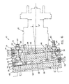
- Fig. 1 is a longitudinal view of the invention.
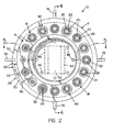
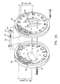
- Fig. 2 is a view of the invention taken on the line 2-2 of Fig. 1.
- Fig. 3 is a view of the invention taken on the line 3-3 of Fig. 1.
- Fig. 4 is a cross-sectional view of the invention taken on the line 4-4 of Fig. 2.
- Fig. 5 is a cross-sectional view of the invention taken on the line 5-5 of Fig. 2.
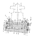
- Fig. 6 is a longitudinal view of the invention providing a positive six degree camber angle.
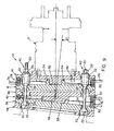
- Fig. 7 is a longitudinal view of the invention providing a negative six degree camber angle.
- Fig. 8 is a top view of the invention providing a six degree slip angle.
- Fig. 9 is a top view of the invention providing a six degree slip angle in a direction opposite that shown in Fig. 8.
- Fig. 10 is a detached and exploded view of a set of wedge rings.
- Fig. 11 is an end view of a respective wedge ring showing the indicia.
- Figs. 12A - 12E show an exploded view of the invention.
- Fig. 13 graphically depicts the SAE J670e Coordinate System.
- the apparatus 10 of this invention allows adjustment of the cant of the axis of rotation of an annular article, such as a tire, with respect to a fixed axis.
- the fixed axis is the axis of the axle upon which the apparatus 10 is mounted.
- the fixed axis is fixed with respect to a back plate of the apparatus 10, and generally extends from the center of the back plate in a perpendicular direction.
- the back plate to which the fixed axis is referenced is the back plate furthest from the annular article.
- the axis of rotation of the annular article is fixed with respect to a spindle plate, and generally extends from the center of the spindle plate in a perpendicular direction.
- the spindle plate to which the axis of rotation of the annular article is fixed is the spindle plate closest to the annular article.
- the axis of rotation of the annular article and the fixed axis are aligned.
- the annular article is a tire
- the axis of rotation of the tire corresponds to the central axis of a spindle 12 that can be attached to the spindle plate.
- the apparatus 10 allows adjusting the cant of the axis of rotation of the annular article, with respect to the fixed axis, in any direction.
- the present invention builds on and extends some of the concepts described in WO-A- 00/49381.
- Fig. 1 shows a longitudinal view of the preferred embodiment of the apparatus 10 of the invention.
- a spindle 12 can be attached to a first spindle plate 14 of the apparatus 10.
- the first spindle plate 14 is connected to a first back plate 16 by a first locking mechanism 18.
- the first back plate 16 is located on a side of the first spindle plate 14 opposite the spindle 12.
- the first locking mechanism 18 is a plurality of blind fasteners 20, as shown in Fig. 4.
- Each of these blind fasteners 20 has two washers 22, each with a spherical portion 24, and a nut 26 for tightening the respective fastener 20.
- a first set 28 of wedge rings 30 is disposed between the first spindle plate 14 and the first back plate 16.
- Each wedge ring 30 has a wider portion 32 and a narrower portion 34.
- the first back plate 16 is attached to a second spindle plate 36 on a side of the first back plate 16 opposite the first spindle plate 14.
- the second spindle plate 36 is connected to a second back plate 38 by a second locking mechanism 40.
- the second back plate 38 is located on a side of the second spindle plate 36 opposite the first back plate 16.
- a second set 42 of wedge rings 30 is disposed between the second spindle plate 36 and the second back plate 38.
- the wedge rings 30 of the second set 42 are identical to the wedge rings 30 of the first set 28.
- the second locking mechanism 40 is a plurality of blind fasteners 20, as shown in Fig. 8.
- Each of these blind fasteners 20 has two washers 22, each with a spherical portion 24, and a nut 26 for tightening onto the respective fastener 20.
- the second locking mechanism 40 may extend beyond the first spindle plate 14. In the preferred embodiment, this is done by having the respective washers 22 apply pressure to the first back plate 16 which is rigidly connected to the second spindle plate 36.
- the second spindle plate 36 and the first back plate 16 may be the same piece; however, this may entail the use of different fasteners.
- each wedge ring 30 When the wider portion 32 of each wedge ring 30 is aligned with the narrower portion 34 of a corresponding wedge ring 30 in the same set 28, 42, the axis of rotation of the annular article is normal to the first and second back plates 16, 38 and the first and second spindle plates 14, 36. At this position, the indicia 44 indicating zero degrees on both sets 28, 42 of wedge rings 30 are aligned with an angle indicating mark 45 located on at least one of the respective plates corresponding with the set 28, 42 of wedge rings 30. When the second set 42 of wedge rings 30 is rotated, the axis of rotation of the annular article moves to an angle that is not normal to the second back plate 38. In this embodiment, the second back plate 38 is fixed with respect to the fixed axis.
- the first back plate 16 remains normal to the axis of rotation of the annular article.
- the axis of rotation of the annular article moves to an angle that is oblique to both the first back plate 16 and the second back plate 38.
- Fig. 2 shows a view of the apparatus 10 taken along line 2-2 of Fig. 1.
- the first spindle plate 14 contains a plurality of holes 46 for receiving fasteners for attaching the spindle plate 14 to the spindle 12.
- Fig. 2 also shows a plurality of fasteners 20, each with a respective washer 22 and a nut 26, forming the first and second locking mechanism 18, 40.
- FIG. 3 shows a view of the apparatus 10 taken along line 3-3 of Fig. 1.
- a support plate 48 attaches to either a vehicle or a tire testing machine.
- the support plate 48 is rigidly attached to the second back plate 38, as shown in Fig. 4.
- the support plate 48 has a plurality of holes 50 that give the second locking mechanism 40 enough space to freely rotate.
- space for rotation may be made available elsewhere, such as on the vehicle or the tire testing machine.
- the support plate 48 and the second back plate 38 may be combined in the same piece; however, this may entail the use of different fasteners.
- Figs. 4 and 5 show cross-sectional views of the invention.
- Fig. 5 is a top plan view showing a first boss 52 and a first register 54.
- the first boss 52 is part of the first spindle plate 14 and the first register 54 is part of the first back plate 16.
- Fig. 4 shows a second boss 56 and a second register 58 which when connected, allows canting of the axis of rotation of the annular article in a second direction, shown as a direction perpendicular to the first direction.
- this cant is called either slip or camber, depending on the direction of the cant.
- the second boss 56 is part of the second spindle plate 36 and the second register 58 is part of the second back plate 38.
- the second boss 56 and register 58 combination allows canting of the axis of rotation of the tire to cause the slip angle
- the first boss 52 and register 54 combination allows canting of the axis of rotation of the tire to cause the camber angle.
- the X-axis and the Y-axis are always located in the plane of the road, the X-Y plane, and depend only upon the heading of the tire.
- the X-axis is defined by the direction of the tire heading and the Y-axis is perpendicular to the X-axis in the plane of the road.
- the Z-axis is always perpendicular to the plane of the road, the X-Y plane, and never moves.
- both the camber and the slip angles are adjusted in the same apparatus 10.
- the first boss 52 and register 54 combination if the movement of the second boss 56 and register 58 combination causes the camber angle, the first boss 52 and register 54 combination, which would control slip, is shifted with the movement of the second boss 56 and register 58 combination in the camber direction.
- the axis about which the slip angle is rotated is not the Z-axis as defined in the SAE standards but is instead a new axis which is angled from the SAE Z-axis by the camber angle y, shown by the line labeled "positive inclination angle" in Fig. 13.
- the first boss 52 and register 54 combination preferably causes the camber angle and the second boss 56 and register 58 combination causes the slip angle.
- each set 28, 42 of wedge rings 30 consists of at least two wedge rings 30.
- a first wedge ring 60 is provided with a boss 64 which is adapted to engage a register 66 of a second wedge ring 62.
- Each wedge ring 30 has a wider portion 32, a narrower portion 34, a back plate side 68, a spindle plate side 70, an outer surface 72, and an inner surface 74.
- the back plate side 68 is located nearest to the respective back plate 16, 38 for that set 28, 42 of wedge rings 30 and the spindle plate side 70 is located nearest to the respective spindle plate 14, 36 for that set 28, 42 of wedge rings 30.
- the indicia 44 used to display the respective angle caused by each set 28, 42 of wedge rings 30 are located on the outer surface 72 of each wedge ring 30.
- the indicia 44 are located nearer the back plate side 68 of the second wedge ring 62 and nearer the spindle plate side 70 of the first wedge ring 60.
- Each wedge ring 30 has a rotating means, such as the handle 76 depicted in Figs. 10 and 11.
- the respective sets 28, 42 of wedge rings 30 may be rotated to change the cant of the axis of rotation of the annular article with respect to the fixed axis.
- each first wedge 60 ring must be rotated in an equal and opposite direction as each second wedge ring 62.
- the angle of movement is displayed by the indicia 44 of the first and second wedge rings 60, 62 aligning an angle indicating mark 45 located on at least one of the respective plates corresponding to that set 28, 42 of wedge rings 30.
- this equal and opposite movement of the wedge rings 30 is required because of the restricted movement resulting from use of the boss and register combinations.
- the angle of the cant of the axis of rotation of the annular article is three degrees in the respective direction.
- Figs. 6 to 9 illustrate how adjustment of the respective wedge rings 30 changes the cant of the axis of rotation of a tire.
- the cant illustrates changes in the camber and the slip angles.
- Figs. 6 and 7 show side views of the invention with a positive and negative camber angle.
- Fig. 8 and 9 show top views of the invention with opposite slip angles.
- the illustrations only demonstrate adjustment of each angle to six degrees, the invention theoretically allows adjustment of each angle up to ninety degrees, limited only by practical application.
- the respective set 28, 42 of wedge rings 30 is locked into place, by tightening the respective locking mechanisms 18, 40, the axis of rotation of the tire is canted in each particular direction at the angle indicated by the indicia 44.
- the axis of rotation of the tire will have a three degree slip angle with respect to the fixed axis. If the first set 28 of wedge rings 30 is at a four degree camber angle, the axis of rotation of the tire will also have a four degree camber angle with respect to the fixed axis.
- Fig. 12 shows an exploded view of a preferred embodiment of the invention.
- the locking mechanisms 18, 40 are blind fasteners 20.
- the use of blind fasteners 20 makes the apparatus 10 easy to build and allows for changing both the slip and camber angles with access to only one side of the apparatus 10.
- the washers 22, each with a spherical portion 24, allows each of the fasteners 20 to make secure contact with the respective plates at all possible angles.
- the method of adjusting the cant of the axis of rotation of an annular article with respect to a fixed axis, using the apparatus 10, includes the steps of: rotating the first set 28 of wedge rings 30 to a first predetermined angle; locking the first set 28 of wedge rings 30 at the predetermined angle; rotating the second set 42 of wedge rings 30 to a second predetermined angle; and locking the second set 42 of wedge rings 30 at the second predetermined angle.
- the steps of rotating the first and second sets 28, 42 of wedge rings 30 can further include indicating the angle of rotation with indicia 44 located on each wedge ring 30 and aligning the indicia 44 of the respective wedge rings 30 to correspond with the respective predetermined angle.
Abstract
Description
- This invention relates to an apparatus for adjusting the cant of the axis of rotation of an annular article with respect to a fixed axis, such as the axis of a vehicle axle or a test machine axle. More particularly, this invention relates to an apparatus for adjusting the camber and/or the slip angle of a mounted pneumatic tire.
- In many applications there is a need to adjust the cant of the axis of rotation of an annular article with respect to a fixed axis. One such application is the need to adjust the camber and/or the slip angles of a mounted pneumatic tire for testing. By varying the camber and the slip angles of the tire, tire designers can determine how the particular tire reacts under given conditions. The data obtained from these tests is helpful in designing tires with an improved working footprint. To aid tire designers in quantifying the test data, SAE J670e Vehicle Dynamics Terminology is used as a standard coordinate system. Another application where there is a need to adjust the camber and/or the slip angle of a mounted pneumatic tire is on a vehicle. In racing vehicles, the camber and the slip of each tire may be individually adjusted for specific track conditions. On a passenger vehicle, the camber and slip may be similarly optimized.
- A spindle is a mechanism used to hold a wheel to a vehicle or a tire testing machine. The center axis of the spindle is normally the axis of rotation for the wheel, and thus for the tire. The angle of rotation of the wheel can be adjusted with respect to a fixed axis, such as the axis of a vehicle axle or a test machine axle. The ease of adjusting the cant of the wheel with respect to the fixed axis is important. On vehicles, the cant of the wheels may be adjusted by adjusting the tie rods. However, adjusting a tie rod adjusts the cant of both wheels that correspond to that tie rod, an act that, at times, may be undesirable. On tire testing machines, many spindle assemblies must be dismantled and reassembled at the new desired cant because of their inability to be adjusted.
- US-A- 3,999,429 entitled "TIRE TESTING APPARATUS" shows a spindle apparatus having a bearing that allows the camber and the slip angle of the tire to be varied. The adjustment of each angle is made by means of two screw-threaded members. Although the patent mentions the spindle as being adjustable, no details are given explaining how the adjusting mechanism works or is controlled. Additionally, the patent gives no information concerning how the given angles are locked into place or how the spindle supports the forces applied by the test vehicle or the tire test machine.
- US-A 5,481,907 entitled "TIRE TESTING SYSTEM HAVING FOCUSED LINKS REDUCING COSINE ERRORS", provides for a tire testing system where both the camber and slip angles are adjustable. The camber and the slip angles are adjusted by the operation of actuators. The patent does not disclose a means of determining the angle of camber and/or slip applied or a means locking a specified camber or slip angle in place. Additionally, since the system is constructed of a number of links, cosine errors, even though reduced in this invention, still occur.
- The apparatus of the invention allows the cant of the axis of rotation of an annular article to be adjusted with respect to a fixed axis. The apparatus has at least one set of wedge rings that are disposed between a back plate and a spindle plate. The back plate, furthest from the annular article, is fixed with respect to the fixed axis and the spindle plate is fixed with respect to the axis of rotation of the annular article. Each wedge ring has a wider portion and a narrower portion.
- In the preferred embodiment, the back plate that is fixed with respect to the fixed axis is a second back plate. The spindle plate that is fixed with respect to the axis of rotation of the annular article is a first spindle plate. The apparatus also has a first back plate and a second spindle plate. The first spindle plate is connected to the first back plate. A first set of wedge rings is disposed between the first spindle plate and the first back plate. The second spindle plate is attached to the first back plate. The second spindle plate also is connected to a second back plate, which is located on a side of the second spindle plate opposite the first back plate. A second set of wedge rings is disposed between the second spindle plate and the second back plate.
- For ease of understanding this disclosure, the following terms are defined.
- "Camber" or "camber angle" means the inclination or tilt of a tire with respect to a plane perpendicular to the ground at a particular point in time when the tire is in motion. It is considered positive when the wheel leans outward at the top and negative when it leans inward. The camber angle is sometimes referred to as the "inclination angle."
- "Cant" means an inclination from a given line or a fixed axis. When used as a verb, cant means to set at an angle.
- "Equatorial plane (EP)" means the plane perpendicular to the tire's axis of rotation and passing through the center of its tread.
- "Footprint" means the contact patch or area of contact of the tire tread with a flat surface at zero speed and under normal load and pressure or under specified load, pressure and speed conditions.
- "Lateral" means an axial direction.
- "Pneumatic tire" means a laminated mechanical device of generally toroidal shape, usually an open-torus, having beads and a tread and made of rubber, chemicals, fabric and steel or other materials. When mounted on a wheel of a motor vehicle, the tire through its tread provides traction and contains the fluid that sustains the vehicle load.
- "Slip" or "slip angle" means the angle between the direction of wheel heading, the X-axis and the direction of wheel travel. The direction of wheel heading is generally in the plane formed by the equatorial plane of the tire.
- The invention will be described by way of example and with reference to the accompanying drawings in which:
- Fig. 1 is a longitudinal view of the invention.
- Fig. 2 is a view of the invention taken on the line 2-2 of Fig. 1.
- Fig. 3 is a view of the invention taken on the line 3-3 of Fig. 1.
- Fig. 4 is a cross-sectional view of the invention taken on the line 4-4 of Fig. 2.
- Fig. 5 is a cross-sectional view of the invention taken on the line 5-5 of Fig. 2.
- Fig. 6 is a longitudinal view of the invention providing a positive six degree camber angle.
- Fig. 7 is a longitudinal view of the invention providing a negative six degree camber angle.
- Fig. 8 is a top view of the invention providing a six degree slip angle.
- Fig. 9 is a top view of the invention providing a six degree slip angle in a direction opposite that shown in Fig. 8.
- Fig. 10 is a detached and exploded view of a set of wedge rings.
- Fig. 11 is an end view of a respective wedge ring showing the indicia.
- Figs. 12A - 12E show an exploded view of the invention.
- Fig. 13 graphically depicts the SAE J670e Coordinate System.
- The
apparatus 10 of this invention allows adjustment of the cant of the axis of rotation of an annular article, such as a tire, with respect to a fixed axis. In a vehicle or on a tire testing machine, the fixed axis is the axis of the axle upon which theapparatus 10 is mounted. The fixed axis is fixed with respect to a back plate of theapparatus 10, and generally extends from the center of the back plate in a perpendicular direction. The back plate to which the fixed axis is referenced is the back plate furthest from the annular article. The axis of rotation of the annular article is fixed with respect to a spindle plate, and generally extends from the center of the spindle plate in a perpendicular direction. The spindle plate to which the axis of rotation of the annular article is fixed is the spindle plate closest to the annular article. When the back plate and the spindle plate of theapparatus 10 are parallel to one another, the axis of rotation of the annular article and the fixed axis are aligned. When the annular article is a tire, the axis of rotation of the tire corresponds to the central axis of aspindle 12 that can be attached to the spindle plate. Theapparatus 10 allows adjusting the cant of the axis of rotation of the annular article, with respect to the fixed axis, in any direction. The present invention builds on and extends some of the concepts described in WO-A- 00/49381. - Fig. 1 shows a longitudinal view of the preferred embodiment of the
apparatus 10 of the invention. Aspindle 12 can be attached to afirst spindle plate 14 of theapparatus 10. Thefirst spindle plate 14 is connected to afirst back plate 16 by afirst locking mechanism 18. Thefirst back plate 16 is located on a side of thefirst spindle plate 14 opposite thespindle 12. In an illustrated embodiment, thefirst locking mechanism 18 is a plurality ofblind fasteners 20, as shown in Fig. 4. Each of theseblind fasteners 20 has twowashers 22, each with aspherical portion 24, and anut 26 for tightening therespective fastener 20. Afirst set 28 of wedge rings 30 is disposed between thefirst spindle plate 14 and thefirst back plate 16. Eachwedge ring 30 has awider portion 32 and anarrower portion 34. - The
first back plate 16 is attached to asecond spindle plate 36 on a side of thefirst back plate 16 opposite thefirst spindle plate 14. Thesecond spindle plate 36 is connected to asecond back plate 38 by asecond locking mechanism 40. Thesecond back plate 38 is located on a side of thesecond spindle plate 36 opposite thefirst back plate 16. Asecond set 42 of wedge rings 30 is disposed between thesecond spindle plate 36 and thesecond back plate 38. The wedge rings 30 of thesecond set 42 are identical to the wedge rings 30 of thefirst set 28. In an illustrated embodiment, thesecond locking mechanism 40 is a plurality ofblind fasteners 20, as shown in Fig. 8. Each of theseblind fasteners 20 has twowashers 22, each with aspherical portion 24, and anut 26 for tightening onto therespective fastener 20. To allow easier access to thesecond locking mechanism 40, thesecond locking mechanism 40 may extend beyond thefirst spindle plate 14. In the preferred embodiment, this is done by having therespective washers 22 apply pressure to thefirst back plate 16 which is rigidly connected to thesecond spindle plate 36. Thus, it is possible for thesecond spindle plate 36 and thefirst back plate 16 to be the same piece; however, this may entail the use of different fasteners. - When the
wider portion 32 of eachwedge ring 30 is aligned with thenarrower portion 34 of acorresponding wedge ring 30 in thesame set second back plates second spindle plates indicia 44 indicating zero degrees on bothsets angle indicating mark 45 located on at least one of the respective plates corresponding with theset second set 42 of wedge rings 30 is rotated, the axis of rotation of the annular article moves to an angle that is not normal to thesecond back plate 38. In this embodiment, thesecond back plate 38 is fixed with respect to the fixed axis. When thesecond set 42 of wedge rings 30 is rotated, thefirst back plate 16 remains normal to the axis of rotation of the annular article. When thefirst set 28 of wedge rings 30 is rotated, the axis of rotation of the annular article moves to an angle that is oblique to both thefirst back plate 16 and thesecond back plate 38. - Fig. 2 shows a view of the
apparatus 10 taken along line 2-2 of Fig. 1. As can be seen in Fig. 2, thefirst spindle plate 14 contains a plurality ofholes 46 for receiving fasteners for attaching thespindle plate 14 to thespindle 12. Fig. 2 also shows a plurality offasteners 20, each with arespective washer 22 and anut 26, forming the first andsecond locking mechanism - Fig. 3 shows a view of the
apparatus 10 taken along line 3-3 of Fig. 1. Asupport plate 48 attaches to either a vehicle or a tire testing machine. On a side of thesupport plate 48 opposite the vehicle or the tire testing machine, thesupport plate 48 is rigidly attached to thesecond back plate 38, as shown in Fig. 4. As shown in Fig. 5, thesupport plate 48 has a plurality ofholes 50 that give thesecond locking mechanism 40 enough space to freely rotate. Those skilled in the art will recognize that space for rotation may be made available elsewhere, such as on the vehicle or the tire testing machine. In such an embodiment, thesupport plate 48 and thesecond back plate 38 may be combined in the same piece; however, this may entail the use of different fasteners. - Figs. 4 and 5 show cross-sectional views of the invention. Fig. 5 is a top plan view showing a
first boss 52 and afirst register 54. Thefirst boss 52 is part of thefirst spindle plate 14 and thefirst register 54 is part of thefirst back plate 16. When thefirst boss 52 and thefirst register 54 are connected, the combination allows canting of the axis of rotation of the annular article in a first direction. Fig. 4 shows asecond boss 56 and asecond register 58 which when connected, allows canting of the axis of rotation of the annular article in a second direction, shown as a direction perpendicular to the first direction. When the annular article is a tire, this cant is called either slip or camber, depending on the direction of the cant. As seen, thesecond boss 56 is part of thesecond spindle plate 36 and thesecond register 58 is part of thesecond back plate 38. Although a boss and register combination is preferred in the invention, any device that allows a controlled movement in a specific direction will work sufficiently. - When the
apparatus 10 is used on a vehicle or a tire testing machine, it is preferred that thesecond boss 56 and register 58 combination allows canting of the axis of rotation of the tire to cause the slip angle, and thefirst boss 52 and register 54 combination allows canting of the axis of rotation of the tire to cause the camber angle. This ensures that the canting of the tire follows the SAE J670e standard. In the SAE standards, the X-axis and the Y-axis are always located in the plane of the road, the X-Y plane, and depend only upon the heading of the tire. The X-axis is defined by the direction of the tire heading and the Y-axis is perpendicular to the X-axis in the plane of the road. The Z-axis is always perpendicular to the plane of the road, the X-Y plane, and never moves. In the illustrated embodiment of the present invention, both the camber and the slip angles are adjusted in thesame apparatus 10. When thesecond boss 56 and register 58 combination is moved by rotation of thesecond set 42 of wedge rings 30, the orientation, with respect to the road surface, the X-Y plane, of thefirst set 28 of wedge rings 30 and the axis of rotation of the tire is changed. As shown in Fig. 13, the slip angle a is measured in the road surface, the X-Y plane, and is created by rotation about the Z-axis as defined in the SAE standards. When the movement of thesecond boss 56 and register 58 combination causes the slip angle, the movement is rotation about the Z-axis. However, if the movement of thesecond boss 56 and register 58 combination causes the camber angle, thefirst boss 52 and register 54 combination, which would control slip, is shifted with the movement of thesecond boss 56 and register 58 combination in the camber direction. Thus, the axis about which the slip angle is rotated is not the Z-axis as defined in the SAE standards but is instead a new axis which is angled from the SAE Z-axis by the camber angle y, shown by the line labeled "positive inclination angle" in Fig. 13. As such, to ensure compliance with the SAE standards, thefirst boss 52 and register 54 combination preferably causes the camber angle and thesecond boss 56 and register 58 combination causes the slip angle. - With reference to Figs. 10 and 11, each set 28, 42 of wedge rings 30 consists of at least two wedge rings 30. A
first wedge ring 60 is provided with aboss 64 which is adapted to engage aregister 66 of asecond wedge ring 62. Eachwedge ring 30 has awider portion 32, anarrower portion 34, aback plate side 68, aspindle plate side 70, anouter surface 72, and aninner surface 74. Theback plate side 68 is located nearest to therespective back plate spindle plate side 70 is located nearest to therespective spindle plate indicia 44 used to display the respective angle caused by each set 28, 42 of wedge rings 30 are located on theouter surface 72 of eachwedge ring 30. Theindicia 44 are located nearer theback plate side 68 of thesecond wedge ring 62 and nearer thespindle plate side 70 of thefirst wedge ring 60. Eachwedge ring 30 has a rotating means, such as thehandle 76 depicted in Figs. 10 and 11. When therespective locking mechanisms respective sets first wedge 60 ring must be rotated in an equal and opposite direction as eachsecond wedge ring 62. The angle of movement is displayed by theindicia 44 of the first and second wedge rings 60, 62 aligning anangle indicating mark 45 located on at least one of the respective plates corresponding to that set 28, 42 of wedge rings 30. In the illustrated embodiment, this equal and opposite movement of the wedge rings 30 is required because of the restricted movement resulting from use of the boss and register combinations. Thus, when theindicia 44 indicating three degrees on thefirst wedge ring 60 is aligned with theindicia 44 indicating three degrees on thesecond wedge 62, the angle of the cant of the axis of rotation of the annular article is three degrees in the respective direction. Those skilled in the art will recognize that alternative arrangements may be used. - Figs. 6 to 9 illustrate how adjustment of the respective wedge rings 30 changes the cant of the axis of rotation of a tire. Here, the cant illustrates changes in the camber and the slip angles. Figs. 6 and 7 show side views of the invention with a positive and negative camber angle. Fig. 8 and 9 show top views of the invention with opposite slip angles. Although the illustrations only demonstrate adjustment of each angle to six degrees, the invention theoretically allows adjustment of each angle up to ninety degrees, limited only by practical application. When the
respective set respective locking mechanisms indicia 44. Thus, if thesecond set 42 of wedge rings 30 is rotated to a three degree slip angle, the axis of rotation of the tire will have a three degree slip angle with respect to the fixed axis. If thefirst set 28 of wedge rings 30 is at a four degree camber angle, the axis of rotation of the tire will also have a four degree camber angle with respect to the fixed axis. - Fig. 12 shows an exploded view of a preferred embodiment of the invention. As shown, the locking
mechanisms blind fasteners 20. The use ofblind fasteners 20 makes theapparatus 10 easy to build and allows for changing both the slip and camber angles with access to only one side of theapparatus 10. Thewashers 22, each with aspherical portion 24, allows each of thefasteners 20 to make secure contact with the respective plates at all possible angles. - The method of adjusting the cant of the axis of rotation of an annular article with respect to a fixed axis, using the
apparatus 10, includes the steps of: rotating thefirst set 28 of wedge rings 30 to a first predetermined angle; locking thefirst set 28 of wedge rings 30 at the predetermined angle; rotating thesecond set 42 of wedge rings 30 to a second predetermined angle; and locking thesecond set 42 of wedge rings 30 at the second predetermined angle. The steps of rotating the first andsecond sets indicia 44 located on eachwedge ring 30 and aligning theindicia 44 of the respective wedge rings 30 to correspond with the respective predetermined angle.
Claims (5)
- An apparatus (10) for adjusting the cant of the axis of rotation of an annular article with respect to a fixed axis, the apparatus being characterized by:
at least one set of wedge rings (30) being disposed between a back plate (16,38) and a spindle plate (14,36), the back plate being fixed with respect to the fixed axis, the spindle plate being fixed with respect to the axis of rotation of the annular article, each wedge ring having a wider portion (32) and a narrower portion (34). - An apparatus as in claim 1, the apparatus being further characterized by:
each wedge ring (30) being rotatable when a locking mechanism is loosened, the spindle plate (14,36) being normal to the fixed axis when the narrower portion (34) of each wedge ring is aligned with the wider portion (32) of a corresponding wedge ring in the respective set, the spindle plate being canted with respect to the fixed axis when the narrower portion of each wedge ring is not aligned with the wider portion of a corresponding wedge ring. - An apparatus as in claim 1, the apparatus being further characterized by:
the back plate (38) that is fixed with respect to the fixed axis being a second back plate, the spindle plate (14) that is fixed with respect to the axis of rotation of the annular article being a first spindle plate, the apparatus further having a first back plate (16) and a second spindle plate (36), the first spindle plate (14) being connected to the first back plate (16), a first set (28) of wedge rings (30) being disposed between the first spindle plate and the first back plate, the second spindle plate (36) being attached to the first back plate (16), the second spindle plate further being connected to a second back plate (38), the second back plate being located on a side of the second spindle plate opposite the first back plate, a second set (42) of at least two wedge rings (30) being disposed between the second spindle plate (36) and the second back plate (38). - An apparatus as in claim 3, the apparatus being further characterized by:the axis of rotation of the annular article moving to an angle oblique to the second back plate (38) when the second set (42) of at least two wedge rings (30) is rotated, andthe axis of rotation of the annular article moving to an angle oblique to both the first back plate (16) and the second back plate (38) when the first set (28) of at least two wedge rings (30) is rotated.
- An apparatus as in claim 3, the apparatus being further characterized by:adjustment of the spindle (12) relative to the first back plate (16) being limited to a first direction by a boss (52) and register (54) combination interconnecting the first back plate (16) and the first spindle plate (14), andadjustment of the spindle (12) relative to the second back plate (38) being limited to a second direction by a boss (56) and register (58) combination interconnecting the second back plate (38) and the second spindle plate (36).
Applications Claiming Priority (2)
| Application Number | Priority Date | Filing Date | Title |
|---|---|---|---|
| US09/489,351 US6374665B1 (en) | 2000-01-21 | 2000-01-21 | Apparatus for adjusting the cant of an annular article |
| US489351 | 2000-01-21 |
Publications (2)
| Publication Number | Publication Date |
|---|---|
| EP1118850A2 true EP1118850A2 (en) | 2001-07-25 |
| EP1118850A3 EP1118850A3 (en) | 2002-09-04 |
Family
ID=23943500
Family Applications (1)
| Application Number | Title | Priority Date | Filing Date |
|---|---|---|---|
| EP01100506A Withdrawn EP1118850A3 (en) | 2000-01-21 | 2001-01-09 | Apparatus for adjusting the cant of an annular article |
Country Status (4)
| Country | Link |
|---|---|
| US (1) | US6374665B1 (en) |
| EP (1) | EP1118850A3 (en) |
| JP (1) | JP2001270464A (en) |
| BR (1) | BR0100041A (en) |
Cited By (2)
| Publication number | Priority date | Publication date | Assignee | Title |
|---|---|---|---|---|
| EP1728653A3 (en) * | 2005-05-30 | 2008-06-11 | Benteler Automobiltechnik GmbH | Adjustable suspension system |
| CN104260781A (en) * | 2014-10-20 | 2015-01-07 | 安徽江淮汽车股份有限公司 | Method for calibrating camber angle and caster angle of wheel |
Families Citing this family (15)
| Publication number | Priority date | Publication date | Assignee | Title |
|---|---|---|---|---|
| US7056053B2 (en) | 2002-11-27 | 2006-06-06 | General Electric Company | Bolting arrangement including a two-piece washer for minimizing bolt bending |
| KR100572264B1 (en) * | 2004-12-23 | 2006-04-24 | (주) 동희산업 | Apparatus for adjusting angle of wheel for suspension system in automobile |
| US7946658B2 (en) * | 2008-12-16 | 2011-05-24 | Rph Irrigation Services Ltd. | Wheel hub, system and method for rut reduction in self propelled irrigation systems |
| DE102009058489A1 (en) | 2009-12-16 | 2011-06-22 | Audi Ag, 85057 | Device for adjusting the camber and / or track of the wheels of motor vehicles |
| DE102010022843A1 (en) * | 2010-06-07 | 2011-12-08 | Gm Global Technology Operations Llc (N.D.Ges.D. Staates Delaware) | Wheel suspension for design study of motor vehicle, has base plate for connecting with substructure of design study and wheel receiver for connecting with rim of motor vehicle tire |
| GB201110436D0 (en) * | 2011-06-21 | 2011-08-03 | Rolls Royce Plc | Joint assembly |
| US9169728B2 (en) * | 2011-12-08 | 2015-10-27 | General Electric Company | Dynamic load reduction system |
| ES2732194T3 (en) * | 2014-01-15 | 2019-11-21 | Tlv Co Ltd | Sensor fixing device |
| US9233713B2 (en) * | 2014-06-13 | 2016-01-12 | GM Global Technology Operations LLC | Adjustable toe curve knuckle for a vehicle suspension and method |
| DE102014011194B4 (en) * | 2014-07-26 | 2020-12-10 | Audi Ag | Wheel carrier for a two-lane motor vehicle with rotation angle stops for toe / camber adjustment |
| US10272729B2 (en) * | 2015-03-10 | 2019-04-30 | Compagnie Generale Des Etablissements Michelin | Indexable washer system for wheel alignment correction |
| MX2017010975A (en) | 2015-03-10 | 2017-10-18 | Michelin & Cie | Indexable system for select wheel alignment correction. |
| ITUB20160349A1 (en) * | 2016-01-21 | 2017-07-21 | Jofa S R L | GROUP FOR THE REGULATION OF THE GEOMETRY OF A SUSPENSION OF A VEHICLE |
| US10247038B2 (en) * | 2016-10-20 | 2019-04-02 | Rolls-Royce Corporation | Flange fastening assembly in a gas turbine engine |
| WO2019046925A1 (en) * | 2017-09-06 | 2019-03-14 | Precision Guide Machinery And Repair Limited | Wedge prism leveling mechanism |
Citations (5)
| Publication number | Priority date | Publication date | Assignee | Title |
|---|---|---|---|---|
| US774042A (en) * | 1904-04-06 | 1904-11-01 | Albert N Cooper | Vehicle-axle. |
| US4867472A (en) * | 1986-06-19 | 1989-09-19 | Ward Arlen T | Wheel steering axis inclination, caster, and camber adjustment assembly |
| WO1994025326A1 (en) * | 1993-04-28 | 1994-11-10 | Specialty Products, Inc. | Apparatus and method for adjusting camber and toe |
| USRE36058E (en) * | 1993-08-20 | 1999-01-26 | Ingalls Engineering Company, Inc. | Multi-element wheel alignment shim assembly, and method of use |
| WO2000049381A1 (en) * | 1999-02-18 | 2000-08-24 | The Goodyear Tire & Rubber Company | Adjustable angle spindle |
Family Cites Families (9)
| Publication number | Priority date | Publication date | Assignee | Title |
|---|---|---|---|---|
| US3581563A (en) * | 1969-06-25 | 1971-06-01 | Goodyear Tire & Rubber | Tire-testing apparatus |
| US3726124A (en) | 1971-03-24 | 1973-04-10 | United Eng Foundry Co | Testing machine for tires and the like |
| US3987672A (en) * | 1974-08-07 | 1976-10-26 | Picker Corporation | Tire inspection system |
| JPS55147333A (en) | 1979-05-04 | 1980-11-17 | Kobe Steel Ltd | Device for applying tire angle to tire tester |
| JPH0749938B2 (en) | 1989-11-02 | 1995-05-31 | 住友ゴム工業株式会社 | Tire contact surface observation device and observation method |
| US5383361A (en) * | 1992-01-31 | 1995-01-24 | Kokusai Keisokuki Kabushiki Kaisha | Wheel balance measuring apparatus |
| US5347842A (en) | 1993-10-19 | 1994-09-20 | F & M Company Limited Partnership | Calibration apparatus for tire test system |
| US5481907A (en) | 1993-12-13 | 1996-01-09 | Mts Systems Corporation | Tire testing system having focused links reducing cosine errors |
| US6082191A (en) * | 1997-01-24 | 2000-07-04 | Illinois Tool Works, Inc. | Inlet conveyor for tire testing systems |
-
2000
- 2000-01-21 US US09/489,351 patent/US6374665B1/en not_active Expired - Fee Related
-
2001
- 2001-01-09 BR BR0100041-1A patent/BR0100041A/en not_active Application Discontinuation
- 2001-01-09 EP EP01100506A patent/EP1118850A3/en not_active Withdrawn
- 2001-01-22 JP JP2001013088A patent/JP2001270464A/en active Pending
Patent Citations (5)
| Publication number | Priority date | Publication date | Assignee | Title |
|---|---|---|---|---|
| US774042A (en) * | 1904-04-06 | 1904-11-01 | Albert N Cooper | Vehicle-axle. |
| US4867472A (en) * | 1986-06-19 | 1989-09-19 | Ward Arlen T | Wheel steering axis inclination, caster, and camber adjustment assembly |
| WO1994025326A1 (en) * | 1993-04-28 | 1994-11-10 | Specialty Products, Inc. | Apparatus and method for adjusting camber and toe |
| USRE36058E (en) * | 1993-08-20 | 1999-01-26 | Ingalls Engineering Company, Inc. | Multi-element wheel alignment shim assembly, and method of use |
| WO2000049381A1 (en) * | 1999-02-18 | 2000-08-24 | The Goodyear Tire & Rubber Company | Adjustable angle spindle |
Cited By (3)
| Publication number | Priority date | Publication date | Assignee | Title |
|---|---|---|---|---|
| EP1728653A3 (en) * | 2005-05-30 | 2008-06-11 | Benteler Automobiltechnik GmbH | Adjustable suspension system |
| CN104260781A (en) * | 2014-10-20 | 2015-01-07 | 安徽江淮汽车股份有限公司 | Method for calibrating camber angle and caster angle of wheel |
| CN104260781B (en) * | 2014-10-20 | 2016-06-15 | 安徽江淮汽车股份有限公司 | A kind of camber angle and back rake angle adjusting process |
Also Published As
| Publication number | Publication date |
|---|---|
| BR0100041A (en) | 2001-10-30 |
| EP1118850A3 (en) | 2002-09-04 |
| JP2001270464A (en) | 2001-10-02 |
| US6374665B1 (en) | 2002-04-23 |
Similar Documents
| Publication | Publication Date | Title |
|---|---|---|
| US6374665B1 (en) | Apparatus for adjusting the cant of an annular article | |
| EP0683894B1 (en) | Tire testing system having focused links | |
| US6431659B1 (en) | Adjustable angle spindle | |
| JP2003004598A (en) | Method for measuring rolling resistance of tyre and apparatus for the same | |
| CN100526839C (en) | Wheel attitude angle measuring instrument and wheel attitude angle measuring method | |
| EP0605849A1 (en) | Tire tread to compensate residual aligning torque | |
| US5257458A (en) | Method and apparatus for determining caster and steering axis inclination angles | |
| US4462253A (en) | Apparatus for mounting a wheel on a balancer | |
| MXPA02006607A (en) | Method of improving steering performance robustness utilizing stiffness non-uniformity in tire/wheel. | |
| JP7083068B2 (en) | Solid tire with shock absorbers | |
| US4344325A (en) | Mechanism for setting slip and/or camber angles in tire testing machine | |
| JP4665625B2 (en) | Tire testing machine | |
| CN116569017A (en) | Tire testing table with hexapod assembly | |
| US6170324B1 (en) | Tire and rim assembly centering method | |
| US6672148B2 (en) | Method of improving steering performance robustness utilizing mass non-uniformity in tire/wheel | |
| US4689998A (en) | Wheeled vehicle test fixture connector | |
| US8938330B2 (en) | Method for characterising and improving the behaviour of a vehicle | |
| CA2359624A1 (en) | Adjustable angle spindle | |
| Ramji et al. | Stiffness properties of small-sized pneumatic tyres | |
| WO2005012868A1 (en) | Method and vehicle testing stand for dynamic running simulation | |
| EP0894251B1 (en) | Tire and rim assembly centering method | |
| GB1584184A (en) | Road vehicle wheel | |
| Drach et al. | Development of a Mobile Tire Test Fixture and Lateral Force Variations Due to Large Camber Angles | |
| JPH0687039B2 (en) | Body lifting device | |
| CN109397980B (en) | Wheel assembly for vehicle durable road test and vehicle |
Legal Events
| Date | Code | Title | Description |
|---|---|---|---|
| PUAI | Public reference made under article 153(3) epc to a published international application that has entered the european phase |
Free format text: ORIGINAL CODE: 0009012 |
|
| AK | Designated contracting states |
Kind code of ref document: A2 Designated state(s): AT BE CH CY DE DK ES FI FR GB GR IE IT LI LU MC NL PT SE TR |
|
| AX | Request for extension of the european patent |
Free format text: AL;LT;LV;MK;RO;SI |
|
| PUAL | Search report despatched |
Free format text: ORIGINAL CODE: 0009013 |
|
| AK | Designated contracting states |
Kind code of ref document: A3 Designated state(s): AT BE CH CY DE DK ES FI FR GB GR IE IT LI LU MC NL PT SE TR |
|
| AX | Request for extension of the european patent |
Free format text: AL;LT;LV;MK;RO;SI |
|
| AKX | Designation fees paid | ||
| REG | Reference to a national code |
Ref country code: DE Ref legal event code: 8566 |
|
| STAA | Information on the status of an ep patent application or granted ep patent |
Free format text: STATUS: THE APPLICATION IS DEEMED TO BE WITHDRAWN |
|
| 18D | Application deemed to be withdrawn |
Effective date: 20030305 |